2009 Second International Conference on Computer and Electrical Engineering
Fractal Based Fragile Watermark
Adeeb Hamdoon Sulaiman
Faiq Sabar Baji
Facility of Information Technology University of Philadelphia Amman, Jordan
[email protected]
Institute of Informatics Iraqi National center For Computers Baghdad, Iraq
Abstract-The protection of ownership and the protection of unauthorized tampering of multimedia data (audio, image, video, and document) have become a major concern for the authors of multimedia. Image authentication verifies the originality of an image by detecting malicious manipulation The protection of ownership and the protection of unauthorized tampering of multimedia data (audio, image, video, and document) have become a major concern for the authors of multimedia. Image authentication verifies the originality of an image by detecting malicious manipulations. Digital watermarking researches have generally focused on two classes of watermarks, Fragile and robust. Fragile watermarks are used for authentication purposes and are capable of detecting even minute changes of the water marked images. Robust watermarks are designed to be detected even when attempts are made to remove them. In This paper, we focus on the first class of watermarking for digital images authentication by creating a mark based on the self similarities blocks properties of fractal encoding. We start with fractal encoding algorithm, then, partitioning the tested image into ranges and domains blocks, finding the pieces of ranges and their corresponding domains by minimizing the distances between them, finally, we create the mark by partitioning the same image into four columns of equal size and compute the mark through the determination of location for domain block parameters in which column number occurs. Keywords-component; Fractgales, Watermark, Fragile)
There have been two main approaches to authenticating images. In the first, a hash value is calculated for the image, and then encrypted using asymmetric or symmetric key encryption algorithm. The second approach is digital watermark, a type of data hiding or steganography. It embeds some data into digital image. The embedding is performed in such a way that the watermark is imperceptible under normal observation conditions.
I.
There are two primary types of digital watermarks, robust and fragile. A robust watermark is designed to resist attacks that include lossy compression, filtering, and geometric scaling. A fragile mark is designed to detect slight changes in the watermarked image with high probability. The main application of fragile watermark is in content authentication. In this paper, we propose a fragile water mark based on fractal coding process. In general terms, a fractal coder exploits the spatial redundancy within the image by establishing a relationship between its different parts. II.
The term fractal was coined by Mnadelbrot in 1975 [1]. A fractal is a geometric shape that can be subdivided into parts such that each of these parts is exactly or approximately equal to the whole.
INTRODUCTION
A. The Fractal Encoding Scheme An image is regularly segmented into two dimensional arrays of B*B pixel blocks, called range blocks. In general, the dimension of an image is 2l*2l,, for example, 512*512 or 256*256, the range block is 2*2, 4*4, 8*8, 16*16 or 32*32. Range blocks are usually encoded following a row by row order, 2D array of range blocks can be denoted as a series of 1D sequence, i.e. я = {Rj} [2].
The applications of digital multimedia have grown immensely in the past five years. Many methods are readily available for synthesizing and editing multimedia information. Unlike analog information, the reproduction of digital media element is simple and robust. Furthermore, a copy of a digital multimedia is identical to the original. Unfortunately, the very same properties that make a digital media element attractive for use and distribution also facilitate the unauthorized use, misappropriation, and misrepresentation. Thus, there is a great interest in developing technology that will help to protect the integrity of digital multimedia element and the intellectual property rights of its owners. 978-0-7695-3925-6/09 $26.00 © 2009 IEEE DOI 10.1109/ICCEE.2009.35
FRACTALS
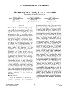
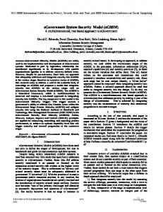
B. Domain Block Pool The domain block pool consists of 2B*2B squares from the original image and is a set of domain blocks. It can be generated by sliding 2B*2B window within the original image by skipping K pixels from the left to right, top to bottom. 141 139
R11 R21 …. …. …. …. …. …. Rm1
R12 R22 …. …. …. …. …. …. Rm2
R13 R23 …. …. …. …. …. …. Rm3
transformations. The first, controlling the spatial part of the transformation, is [3].
R14 R24 …. …. …. …. …. …. Rm4
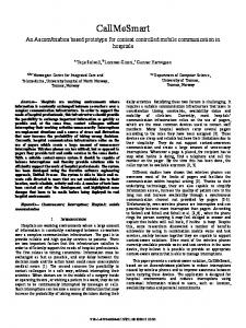
…. …. …. …. R1n …. …. …. …. R2n …. …. …. …. …. …. …. …. …. …. …. …. …. …. …. …. …. …. …. …. …. …. …. …. …. …. …. …. …. …. …. …. …. …. Rmn \ Figure. 1 : Segmenting an image into a set of range blocks
V(x,y) =
ai
bi
x
ci
di
y
+
ei
(2)
fi
The second controls the intensity transformation and given by U(z) = si z + oi
(3)
.
K
Domain Block
Separating the affine transformation in this manner allows us to optimize the transformation for the contrast brightness coefficients, s and o. Representing the image as a set of transformed subregion does not form an exact copy of the original image, but a close approximation of it. Minimizing the error between R^I and Ri (domain and range blocks) will minimize the error between the original image and the approximation. Thus, dissimilarity metric is used to find the” best” transform to map Di to Ri. In practice, it is convenient to choose the rms (root mean square) metric. The rms error between two images f and g is [3,4,5]
2B
2B
M-1, N-1 Drms = √( 1/(M*N) )∑ ∑(f(x,y)-g(x,y))2 X=0 y=0
Figure. 2 The domain block pool
If the image is M*M, then there are [(M-2B/K) +1]* [(M-2B/k )+1] such blocks. For example, if the size of the imager is 256*256, range block is 4*4, the step-size K = 4, then there are 63*63 domain blocks among the domain block pool. Comparing the range block with all domain blocks in the pool one by one, find the best-pair domain block. How to find the best- pair is discussed in the next section.
Minimizing drms for all of the coefficients in equation (1) is a complex task. However, if the optimization is only performed for the contrast and brightness coefficients ( s and o), then minimizing drms becomes a least square computation. In this case, for two square sub-regions of equal size, d and r, there is an s and o that minimize n S = Σ (sdi + o – ri)2 (5) I=1 Where S is the squared error, di is the ith pixel of d, and ri is the ith pixel of r. This can be expanded to n S = no2+ Σ(s2di2+2sdio-2sdiri-2ori+ri2) (6) I=1 The minimum of S occurs when the partial derivatives of S with respect to s and o are equal to zero, i.e., n δS/δs = Σ(2sdi+2sdi2 – 2diiri) = 0 (7) i=1
C. Affine Transformation An Affine transformation is a mapping of a domain block into a range block. The following equation represent the affine transformation: Wi
x y z
=
aI ci 0
bi di 0
0 x 0 * y sI zi
+
ei fi oi
(4)
.(1)
Where si represents the contrast, oi the brightness of the transformation and z = f(x,y). The transformation W has to be contractive in all three directions: x,y and z. That transformation will be contractive when z distances are shrunk by factor less than 1. In practice, it is convenient to separate the transformation given in Equation (1) into two
and
δS/δo = 2no + Σ(2sdi-2ri) = 0 Solving for s and o gives {5,6}
140 142
(8)
n n nΣdiri-ΣdiΣri i=1 i=1 s = -------------------n n nΣdi2 – (Σdi)2 i=1 i=1
(9)
n n O = 1/n [ Σri – Σdi] i=1 i = 1
(10)
1) For the first Experiement, we have: a) Table (1), shows the watermark bits that are resulted from applying the fractal encoding process on the Bridge image shown in figure (5-a). These bits are the results of create fragile watermark step. b) Figure (5-b), shows the Bridge image after hiding the bits obtained from the create fragile mark step. Were we applying the hiding process to hide the bits in Table (1). This process embed two bits (00, 01, 10 or 11) of the mark in LSB of each block. This process is the hiding fragile mark step.
And
For these values of s and o, n n n n n S =[Σri2+s(sΣdi2-2Σdiri+2oΣdi)+o(on-2Σri)] i=1 i=1 i=1 i=1 i=1
c) Table (2), shows the of the extracted mark. These bits are obtained by the extract fragile watermark step.
(11)
d) Table (3), contains the mark bits generated by Reapplying the fractal coding process on the received image
And Drms= √S/N
e) By comparing the bits in table (2) with that of table (3). We find that they are equal whivh indicates that the image is authentic, ie. It has not been temoerdwith.
(12)
Where n = 2 or 4 (the size of the blocks) III.
THE PROPOSED WATERMARK
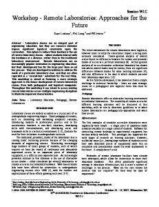
This section focuses on the implementation of Fractal coding system to create fragile watermark, then uses it for authentication. Two methods are used to verify the authenticity of the image. The first is by hiding two bits of the watermark in each LSB of block, this is a fragile watermark. The second method is used to determine the location of change by hiding of the location of mapping between similar block. Figure (3) shows the block diagram of the proposed watermark. IV.
CREATE MARK BY USING FRACTAL
This section shows how the fractal encoding is used to create watermark. For example, when we take the image size of 256*256, as shown in figure (4-a), and the block size is 32*32, then the image is partitioned into 8*8 blocks called Range-image as shown in figure (4-b), and 4*4 blocks called Domain-image as shown in figure (4-c). The domain image is partitioned into four columns of equal size named (C1 ,C2 , C3 and C4 ) . When we apply the fractal-encoding process, we find the block, R2,4 in pool of range which is similar to block, D33 in pool of domain, and at the same time the location of block R2,4, which is column C2 of the pool of domain. This gives the result of the mark (1,0), as shown in figure (4-d). This process is repeated for all of the range blocks V.
(b) Mark Extraction and Authentication Checking Figure 3 The block diagram of the proposed System
RESULTS
2) For the second experiment, we have: to suppose that the marked image of figure (5-b) has been subjected to an attack by hiding the following message in it. :
We made two experiments to check the authentication process, the first experiment to show that when the image is not tempered with the watermark will not change while the second experiment shows that tempering with the image will be detected.
“In a world where privacy is a right, many people try to find a way to hide information especially when it comes to sensitive documents and files”
141 143
TABLE 1 the created watermark for the Bridge image Of size 256*256
a) Table (4), contains the bits of hidden authentication mark extracted from the received test image of figure (5-b). b) Table (5), contains the bits of the authentication mark obtained by applying the fractal encoding on the received image. c) Comparing the bits in table (4) with that of table (5) we find that there are 17 mismatches. This indicates that the image has been tempered with. So the image is not authentic.
VI.
CONCLUSIONS
1) In this work we presented a watermarking scheme that uses the similarities properties of fractal coding. This type of marks is called (fragile watermark) is sensitive to changes to the image data. The sensitivity could be increased with the increases of the number of bits of the hidden mark. 2) We used two bits of marks in each block of image; this could make the matching between the extracted and computed watermarks at the receiver side ineffective. 3) The proposed watermark is suited for authentication, but not suited for copyright protection, this is because the fragile watermark can be destroyed by an attacker.
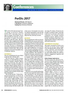
(a) (b) Figure 5 a- The Bridge Image before Inserting the watermark bits b- The Bridge Image after inserting the watermark bits.
Figure 4 Illustration of the create Watermark process
142 144
TABLE 2 The bits of watermark for the received Bridge image of Fig. 5-b.
TABLE 3The bits generated by re-applying Fractal coding on the received Bridge image..
TABLE4 The bits of the watermark for the received Bridge Image.
TABLE5 The bits generated by re-applying Fractal coding on the received Bridge image.
REFERENCES
Transaction on Image Processing. Vol. 1, January 1992, pp. 18-30. [5] B. Grinstead, Content-Based Compression of Mammograms, Master Degree Thesis, Chicago University of Electrical Engineering, 2001. [6] N. HenK, Fractal Image Compresion, http:/www.Cwi.h/Cwi/project/fractals, 1997.
[1] B.Mandelbort, The Fractal Geometry of Nature,, W.H. Freeman and company, 1983. [2] Fractal Image Compression, http://inls.ucsd. tedu/fracals, 1995.
[3] Y. Fisher, Fractal Image Compression Theory and Application, Springer Verlag Edition, New York, 1995. [4] A.E. Jacquin, Image Coding Based on a Fractal Theory of Iterated Contractive Image Transformation. IEE
143 145