PSNR gains of 5 dB or more are typical for packet loss probability as low as 5%. ..... nomenclature stems from the fact that, if (6) is true, one can read the samples ...
Hindawi Publishing Corporation EURASIP Journal on Applied Signal Processing Volume 2006, Article ID 53623, Pages 1–17 DOI 10.1155/ASP/2006/53623
Frame-Based Multiple-Description Video Coding with Extended Orthogonal Filter Banks R. Bernardini,1 M. Durigon,1 R. Rinaldo,1 A. Vitali,2 and P. Zontone1 1 Dipartimento
di Ingegneria Elettrica, Gestionale e Meccanica, Universit`a degli Studi di Udine, via delle Scienze 208, 33100 Udine, Italy 2 ST Microelectronics, via C. Olivetti 2, 20041 Agrate Brianza, Italy Received 4 August 2004; Revised 20 December 2004; Accepted 21 February 2005 We propose a frame-based multiple-description video coder. The analysis filter bank is the extension of an orthogonal filter bank which computes the spatial polyphase components of the original video frames. The output of the filter bank is a set of video sequences which can be compressed with a standard coder. The filter bank design is carried out by taking into account two important requirements for video coding, namely, the fact that the dual synthesis filter bank is FIR, and that loss recovery does not enhance the quantization error. We give explicit results about the required properties of the redundant channel filter and the reconstruction error bounds in case of packet errors. We show that the proposed scheme has good error robustness to losses and good performance, both in terms of objective and visual quality, when compared to single description and other multiple description video coders based on spatial subsampling. PSNR gains of 5 dB or more are typical for packet loss probability as low as 5%. Copyright © 2006 Hindawi Publishing Corporation. All rights reserved.
1.
INTRODUCTION
Robust transmission of multimedia streams over error-prone packet networks has become an important issue in many scenarios, including wireless communications and distributed networking. In such applications, the usual approach of error recognition and packet retransmission may not be appropriate, because of the excessive delay caused by this technique. Moreover, a return channel may not exist or be inconvenient to use in applications with low-power simplified receivers. The use of error-correcting codes at the packet level is not useful when packets are lost because of congestion or delay, or when one of the different paths used for the packets, as in layered coding, totally fails. Recently, forward error correction (FEC) coding across packets has been suggested for robust transmission in the presence of packet losses [1]. In its simpler implementation, this technique consists in grouping N consecutive packets produced by the coder and in adding M − N “parity-check” packets, calculated by means of a block coder (e.g., a Reed-Solomon coder) applied across the N packets on a symbol-by-symbol basis. It has been noticed that this technique has a quick performance drop as soon as the packet loss rate exceeds the error recovery capability of the code. This is due to the fact that when error correction is not possible, the received information is totally useless [2].
Multiple description (MD) coding is a recently proposed solution, where a set of correlated, equally important descriptions of the source are generated at the coder and sent over independent channels [2]. Ideally, each of the descriptions should allow for a reasonable reconstruction of the source, permitting an increased quality as the number of received descriptions increases. Therefore, unlike the case of error-correcting codes, each piece of received information can be useful to increase the reconstruction quality. The requirement that each description is “good by itself ” can be achieved by adding correlation, at the expense of a decrease in the overall rate-distortion performance. Many approaches have been proposed to design MD coders that use different strategies for coding different data sources. MD coding comprises a very wide range of techniques such as MD scalar quantization [3], pairwise correlating transforms [4], spatial and temporal downsampling [5], correlating filter banks or frames [6], and matching pursuit algorithms [7]. Such approaches differ in terms of overall rate-distortion performance and complexity. For a more complete overview of MD techniques see, for example, the introductory paper [2] and references within. A technique for MD of video in the spatial domain is presented in [8]. Each video frame is downsampled in order to create several descriptions of the source ([5] presents a similar technique for still images). Each video subsequence
2 is then independently coded with the H.263 coder. A mechanism for changing the amount of redundancy among the descriptions is reported in [5]. An adaptive procedure for spatial and temporal downsampling is in [9]. The technique proposed in [8] is attractive because it allows for the use of a standard video codec on individual descriptions. Moreover, it offers compatibility with non-MD receivers and good error resilience, because missing information can be interpolated from the received one. Even in the case when only one description is received, the reconstruction quality can be acceptable. Any loss in the received streams, however, has to be appropriately recovered by approximate concealment techniques. In this paper, we propose an MD video coding scheme where two descriptions are obtained by spatial polyphase subsampling in the column direction, and a third description is obtained by lowpass filtering the columns of the original video frames, followed by subsampling. Each of the descriptions is coded with an H.264 coder [10], the international standard currently vying to replace MPEG-2 for widespread technologies such as digital television, Internet streaming video, and DVD-Video [11]. We therefore extend the approach of [5, 8] by adding a visually consistent “paritycheck” image. As a matter of fact, this MD generating procedure can be interpreted within the framework of overcomplete bases expansion (frames) [6]. Frame expansions [6] permit exact reconstruction of lost information even in the presence of data losses, at the expense of added redundancy. General theorems of frame theory claim that the original signal can be obtained by linearly combining a set of suitable signals (such a set is known as the dual frame), using as coefficients the outputs of the analysis filter bank. In case of coefficient losses, however, the dual functions depend on the loss pattern and have to be computed at the receiver [12, 13]. The proposed approach combines the advantages of the MD schemes of [5, 8] with the error recovery capability provided by frame expansions. Error recovery can in fact be done exactly, similarly to what happens with FEC coding, when losses are not too numerous, that is, when the analysis basis after losses is still a complete system. It differs from FEC in that redundancy is added at the signal level, and that the dual functions after losses may cause some amplification of the quantization error, even if the overall system was designed to achieve perfect reconstruction. Moreover, even if losses are so numerous that the system becomes incomplete, one can resort to using the source implicit redundancy, as in [5, 8], and reconstruct the signal with good fidelity. The price to pay is the cost of the additional parity-check video sequence. The experimental results show that the proposed scheme is indeed competitive for relatively high bit rates and loss probability. Toward the design of the proposed scheme, we derive some general theoretical results. First, we show how to construct redundant FIR filter banks by adding a redundant channel to a generic orthogonal filter bank, while preserving FIR reconstruction. Since the spatial polyphase subsampling we consider in the proposed MD video coding scheme is just a very special case of an orthogonal filter bank, we
EURASIP Journal on Applied Signal Processing can use this result for the design of the redundant channel filter. On the other hand, since orthogonal filter banks are ubiquitously used in subband and transform coding, the results we present in this paper can be used for the extension of other available schemes. We then consider the general problem of quantization error enhancement due to the use of nonorthogonal bases expansions. This problem cannot be avoided in overcomplete frame expansions in the presence of coefficient losses. We give explicit results on error bounds and derive criteria for filter bank design to mitigate the effect. We compare the performance of the proposed solution with that of two MD coding schemes based on spatial subsampling. In particular, one of the schemes produces four descriptions based on the four spatial polyphase components of the original frame, while the second scheme is similar to the one we propose here and considers even and odd rows separation. Bilinear interpolation from correctly received frames is again used for error concealment. Note that, unlike the case of frame-based analysis, “exact” error recovery is never possible in the latter two systems in the presence of packet losses. In all schemes, individual descriptions are coded using independent H.264/AVC video coders. After error recovery or concealment, frames are copied onto the decoders’ frame buffers at the receiver, in order to mitigate the effect of error propagation due to differential coding. The organization of the paper is as follows. Section 2 recalls some basic tools and the notation used in this paper. In Section 3 we describe in some detail the proposed MD video codec. In Section 4 we present some experimental results evaluating the rate-distortion performance of the proposed scheme, comparing it with the other two MD schemes and with standard single-description (SD) coding. Section 5 draws the conclusions. 2.
FRAMES AND FILTER BANKS
In this section, we briefly recall some results of frame theory which will be used in this paper [14]. A family of signals Φ = {φk ∈ � 2 (Z)}k∈Z constitutes a frame if for any signal x ∈ � 2 (Z) there exist two constants 0 < A and B < ∞ such that A� x � 2 ≤ �
� �� �� � x, φk �2 ≤ B �x�2 ,
(1)
k∈Z
where � f , g � = n f (n)g ∗ (n) is the scalar product between f and g. Linear function F : � 2 (Z) → � 2 (Z) defined as �
yk = (Fx)k � x, φk
�
(2)
maps x into the corresponding sequence of scalar products and it is known as the frame (or analysis) operator associated with Φ. The left-hand inequality in (1) guarantees that it is possible to reconstruct the original signal x from the scalar products y = { yk }k∈Z and that it is possible to compute a set of dual signals φ�k such that x = F† y =
�
k∈Z
yk φ�k .
(3)
R. Bernardini et al.
3 Nc Nc
Nr /2 h0
2
h1
2
Nr
h2
2
Nc Nr /2 Nc Nr /2
H.264 enc. H.264 enc. H.264 enc.
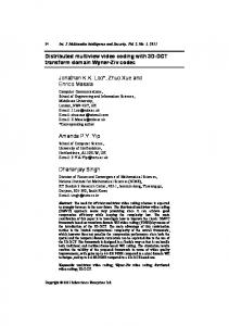
Figure 1: Block diagram of the proposed frame-based MD coder.
The operator F † is called the dual or pseudoinverse operator of F. Moreover, the left-hand inequality in (1) grants for a robust reconstruction, in the sense that if y� = y + � is a noisy � version of y and x� = F † y� = k∈Z y�k φ�k is the reconstructed signal, then �x − x��2 ≤
���2
A
,
(4)
that is, coefficient error is not amplified more than 1/A. In addition, reconstruction via F † is optimal, in the sense that x� = F † y� minimizes �F x� − y�� [15]. Suppose that during the transmission some coefficients yk are lost and let I be the set of the indexes of the lost coefficients and let yI c be the sequence of received coefficients. If subset ΦI � {φk , k ∈ I } is still a frame, one can recover x by “pretending” that it was analyzed with subframe ΦI . If FI is the frame operator corresponding to ΦI , one can obtain x as x = FI † yI c . Operator FI † can be efficiently implemented by means of the algorithm suggested in [12, 13] which expresses FI † as FI † = F † R, where R is a restoring operator which recovers the missing coefficients from the known ones. In the framework of oversampled filter banks, one computes a vector of output coefficients in each channel j = 1, . . . , N, via convolution, that is, y j (n) =
�
x(m)h j (Mn − m),
j = 0, . . . , N − 1 > M − 1.
m∈Z
(5) The right-hand side of (5) can be interpreted as the scalar product between the input and the analysis vector φNn+ j (m) � h j (Mn − m). By appropriate filter design, the φNn+ j constitute a frame. Oversampling, that is, choosing N > M, implies that there is redundancy in the coefficients y j (n) which can be exploited to reconstruct x even if some coefficients are lost. It is possible to show that the dual frame of (5) can be implemented by means of an oversampled synthesis filter bank which will be called the dual filter bank of (5) [16]. If both filter bank (5) and its dual are made of FIR filters, we will say that (5) is a doubly FIR (DFIR) filter bank. The use of DFIR filter banks is ubiquitous in image and video processing, due to ease of implementation and the problem of signal extension at the borders in the spatial direction when using IIR filters. Finally, let us introduce some terminology. A filter bank like the one in (5), with N channels and sampling factor M,
will be called an N/M filter bank. If the first M impulse responses are h j (n) = δ(n + j),
j = 0, . . . , M − 1,
(6)
the first M channels operate a polyphase decomposition of the input signal and we will say that (5) is a systematic filter bank, the first M channels are the systematic channels and the remaining N − M ones are the redundant channels. This nomenclature stems from the fact that, if (6) is true, one can read the samples of signal x by directly looking at the first M channels. 3.
SYSTEM OVERVIEW
The MD scheme proposed in this paper uses standard H.264/AVC coders on the output of an oversampled filter bank operating in the spatial direction and originating three video subsequences y j . A detailed description of the system is shown in Figure 1. The descriptions are generated using a 3/2 one-dimensional filter bank applied to columns of every sequence frame. The filter outputs are subsampled by a factor 2. Thus, for an Nr × Nc input frame, the scheme originates 3 descriptions with dimension Nr /2 × Nc pixels. The descriptions are coded using three independent H.264/AVC standard coders, as shown in Figure 1. Note that the compressed streams have a standard format and this allows non MD-enabled decoder to decode the MD stream by simply keeping one description and discarding the others. This back-compatibility issue can be quite important. The system structure implies that one must use filters such that sequences y j are compressible by the standard coder. For example, since an H.264/AVC coder is used, filters h j must not be highpass since the generated sequences would be difficult to code. For the sake of simplicity, we choose a systematic filter bank, that is, h0 (n) = δ(n), h1 (n) = δ(n + 1). This actually corresponds to send the even rows to the first channel and the odd rows to the second one. The third filter h2 (n) is a lowpass filter, designed according to the criterion described in Section 3.1. The H.264/AVC coder divides the input frame into slices made from macroblocks (MB) organized into rows. Each slice is then sent over the network in a single packet. The reason for subsampling along the columns is that the loss of
4
EURASIP Journal on Applied Signal Processing Nc Nr /2 H.264 dec. H.264 dec. H.264 dec.
Nc Nr /2 Nc
R
Nr /2
2
h�0
2
h�1
2
h�2
Nc Nr +
Concealed frames
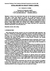
Figure 2: Block diagram of the proposed decoder.
one slice results in a limited number of contiguous lost coefficients in each column, hopefully permitting error recovery. It is easy to see that the slice organization of H.264/AVC implies that the loss of a single packet gives rise to the loss of a rectangular region in one video frame of a subsequence, whose dimensions is equal to the dimensions of a slice. Since we are applying the filter bank columnwise, a loss of a rectangle of coefficients will look like a loss of Sh consecutive coefficients, where Sh is the slice height. In other words, the synthesis filter bank will experience losses in bursts whose length is a multiple of Sh . On the receiver side (Figure 2), the video streams are independently processed by H.264/AVC synchronized decoders. In [12, 13], a practical algorithm for dual frame computation with low delay and reduced complexity is presented. The scheme of [12, 13] puts in front of the synthesis block a restoration stage which recovers, whenever possible, the missing coefficients from the received ones, “hiding” the losses from the synthesis filter bank. The decoders are therefore connected to a restoring block R, which recovers channel errors by implementing the algorithm of [12, 13] when ΦI is still a subframe. In this case, the cascade of the restoring procedure with the original dual filter bank is indeed equivalent to the dual of the lossy frame operator ΦI . We remark that this solution needs only local information and does not introduce any relevant delay in the decoding process. Moreover, the computational complexity is reasonable, since it basically requires the inversion of a matrix with dimension corresponding to the number of lost coefficients in a column (see [12, 13] for a detailed discussion). When slices are lost in the same position in two out of three descriptions, ΦI becomes incomplete and missing regions have to be recovered using an approximate concealment technique. In particular, we interpolate one missing systematic channel from the correctly received stream using bilinear interpolation, then feed these two subimages to the usual restoring block.1 This typically gives acceptable results, due to the high spatial correlation among descriptions in the proposed scheme. In Section 4 we will see a temporal interpolation technique that slightly improves reconstructed video quality in case of incomplete ΦI . Another important aspect in using the H.264 1
When two channels out of three are received, ΦI is indeed a frame.
codec is to avoid error propagation due to direct-mode prediction [10]. If a reference frame (e.g., a P frame) is lost, B slices coded in direct mode cannot be decoded, even if the data relative to the B frame are received correctly. The solution we adopt is to mark B blocks as lost when they are coded in direct mode with respect to corrupted reference information, and to treat them as those lost because of channel failures. The output of the restoring block, with concealment in case of unrecoverable errors followed by application of the algorithm of [12, 13], is a set of three recovered subframes with dimension Nr /2 × Nc . These subframes are then fed into the synthesis filter bank, whose output is an approximation of the original full-size sequence. Recovered subframes for each description are copied into the corresponding decoder frame buffer, in order to limit error propagation from reference frames due to interframe coding. 3.1.
System design
In order to make the scheme of Figure 1 effective, it is necessary to design the third filter h2 . As anticipated, h2 must be a lowpass filter since its output must be a compressible sequence. Moreover, h2 must be such that the filter bank in Figure 1 is DFIR and such that the lower bound resulting after the loss of one packet is as large as possible. In this section, we solve this problem by presenting a general analysis and providing results for the solution of the following problems which generalize the problem of designing h2 . (1) Given an orthogonal filter bank with M channels, we want to add a redundant channel so that the resulting filter bank is doubly FIR. (2) We want to design a systematic (M + 1)/M DFIR filter bank so that the lower bound of subframe Φ resulting after losses is as large as possible. When losses occur, we implicitly analyze the signal with a frame with a smaller lower bound, and this may cause quantization error enhancement according to (4). In the following we will give a necessary and sufficient condition on the redundant channel filter to result in a doubly FIR filter bank. The second problem is more complex and we will derive lower and upper bounds on the frame bound AI , which can be used to limit the overall reconstruction
R. Bernardini et al.
5
error according to (4). The bounds are written as a function of the polyphase components of the (M + 1)th redundant channel filter, so they can be used for the filter choice or design. We take into account the case of L consecutive coefficients lost in a channel. This hypothesis derives from the fact that we are considering a framework where coefficients from each channel are grouped into packets, and a packet loss corresponds to a set of consecutive coefficients missing at the receiver. 3.1.1. Doubly FIR filter banks In detail, we will analyze the following problem. Problem 1. Let h j , j = 0, . . . , M − 1, be the impulse responses of an orthogonal M/M FIR filter bank. Find a filter g such that the resulting (M + 1)/M filter bank is a doubly FIR filter bank. The solution to Problem 1 is contained in the following theorem. Theorem 1. Let h j , j = 0, . . . , M − 1, and g be as in Problem 1. The filter bank made of h j , j = 0, . . . , M − 1, and g is doubly FIR if and only if �
g(n)g(n − Mk) = �g �2 δ(k),
∀k ∈ Z,
(7)
n
that is, if and only if g is orthogonal to its own translations of multiples of M. Proof. Let gk (n) = g(k + nM) be the kth polyphase component of g and let Gk (z) be its z-transform. The polyphase matrix relative to the new filter bank is
H(z) H(z) K(z) = , = G0 (z) G1 (z) · · · GM −1 (z) Gt (z)
(8)
where H(z) is the polyphase matrix of the orthogonal filter � t G (z) G1 (z) · · · GM −1 (z) bank h0 , . . . , hM −1 , and G (z) = 0 is the transpose of the vector of the z-transforms of the polyphase components of g. According to Cvetkovi´c and Vetterli [16] the extended filter bank is doubly FIR if and only if
�
�
r(z) � det Kt z−1 K(z) = αz−k ,
∃α ∈ C, k ∈ Z.
It is clear that (11) is a constant if and only if r(z) − 1 = −1 k=0 Gk (z )Gk (z) is. Observing that r(z) − 1 is the ztransform of the sampled version of the correlation of g, it follows that r(z) is a constant, and the filter bank is doubly FIR, if and only if (7) is true, that is, g is orthogonal to its own translations. �M −1
A consequence of Theorem 1 is that, if M = 2, the only possible filter with linear phase resulting in a doubly FIR filter bank is the 2-tap Haar filter [18]. If we consider a systematic filter bank, as we will do in the proposed video coding scheme, this implies to work blockwise. More precisely, the filter bank is equivalent to mapping each pair of consecutive samples into the triple made of the two samples and their average. If linear phase is necessary, as in image and video coding applications, and one does not want to work blockwise, the dual filter bank will necessarily have IIR impulse responses. In this case, if the decay of the impulse responses of the resulting IIR filters is fast enough, the dual filters can be approximated with possibly short FIR filters, for example, by truncation of the filter kernels. The corresponding DFIR filter bank introduces a small error in the reconstruction process which can be negligible in coding applications. The situation is similar to what happens for nearly perfect reconstruction orthogonal filter banks, where linear-phase filters can be used at the expense of a small error in the reconstruction [14]. 3.1.2. Reconstruction error in response to packet losses The second problem we consider is the design of the redundant channel filter in a systematic filter bank to allow for a “good” reconstruction even in presence of packet losses. This means that the lower bound of ΦI must be as large as possible. As mentioned, we take into account the case of L consecutive coefficient losses in each channel. We will therefore analyze the lower bound of ΦI when a set of L consecutive coefficients is lost in a single channel. Property 1. Let h j , j = 0, . . . , M, be the impulse responses of an (M + 1)/M systematic filter bank and let y j (n) =
(9)
�
x(m)h j (Mn − m).
(12)
m
By observing that
�
r z−1 = det Kt (z)K z−1
��
= det
��
�
Kt z−1 K(z)
�t �
= r(z),
(10) it follows that (9) is true if and only if r(z) is a constant. With some algebra and by exploiting well-known results about determinants [17], one can write
�
�
r(z) = det Ht z−1 H(z) + G z−1 Gt (z)
�
� � = det I + G z−1 Gt (z)
� = 1 + Gt (z)G z−1 = 1 +
M −1 � k=0
�
Gk z−1 Gk (z).
(11)
Let 0 ≤ c ≤ M and suppose that a burst of L coefficients of the cth channel, that is, coefficients yc (n), n = 0, . . . , L − 1, are lost. Let ΦI and AI be the corresponding subframe and its lower bound, respectively. Then, if c = M, we have AI = 1; otherwise �
��2 minω �Hc,M e jω � √ 1+T +2 T ≤ AI
�
�
��2 L − Nc + 1 2 Nc − 1 �hc,M �21 ≤ + min �Hc,M e jω � . ω L L (13)
6
EURASIP Journal on Applied Signal Processing
In (13), Nc is the length of hc,M (n) = hM (c + nM), the cth polyphase component of hM , while T is the 1-norm of the autocorrelation of filter hM sampled with a factor M, namely, T�
�� � �r(n)� = �r �1 ,
r(n) �
n∈Z
�
hM (m)hM (m − Mn).
m
(14) The proof for the upper bound is reported in the appendix, Proof A.1, while the proof for the lower bound is in the appendix, Proof A.2. Note that when L � Nc , the right-hand side of (13) is approximately equal to �
��2 min �Hc,M e jω � . ω
(15) 4.
This suggests the following criterion to achieve a small reconstruction error in response to packet losses. Criterion 1. Suppose bursts of coefficient losses are expected and let hM be the (M + 1)th filter of an (M + 1)/M systematic filter bank. Choose hM such that min
c∈{0,...,M −1}
where MSE is the mean squared reconstruction error with the input. The same reconstruction quality is obtained, with no quantization, with the video sequences we consider in Section 4. Let us now consider the performance of the filters when losses and quantization are taken into account. Figure 3 compares the amplitude of the frequency responses of the two polyphase components of the 4-tap symmetric and Daubechies filters. As we can see, the 4-tap Daubechies filter has a smaller minimum in the first polyphase component. From (16), we conclude that the symmetric filter should perform better than the 4-tap Daubechies filter. This will be confirmed by the results in the experimental section.
�
��2 min �Hc,M e jω � ω
(16)
is as large as possible. 3.2. MD 3 video codec: choice of the filter From the results of Section 3.1, the filter for the redundant channel in the systematic filter bank under consideration should be chosen according to Criterion 1. We took into account the four- and eight-tap lowpass filters from the well known family of Daubechies filters [14] reported in Table 1. These two filters are orthogonal to their even translations, and therefore the resulting filter bank is exactly DFIR. We also considered a linear-phase redundant channel filter. In the following, we will refer to this filter as the symmetric 4-tap filter (Table 1). The use of a linear-phase filter can be useful for video coding purposes, also because it allows for symmetric rather than periodic signal extension in the analysis stage. Moreover, the symmetric filter was designed according to Criterion 1. As we will see, its performance is actually better than that of the 4-tap Daubechies filter and is comparable to that of the 8-tap Daubechies filter. Since the symmetric filter is not orthogonal to its translations, the hypotheses of Theorem 1 are not met exactly, and the resulting filter bank has IIR synthesis filters. These are very well approximated by the FIR filters of Table 2. The impulse responses of the dual filter bank are truncated to make the system DFIR so that the overall reconstruction error is negligible. In particular, it is easy to see that, when the input is modeled as a random process uniformly distributed in [0, 255], the cascade of the FIR analysis and synthesis filter banks, with no quantization, allows for a peak signal-tonoise ratio (PSNR) of about 60 dB. The PSNR is defined as PSNR � 10 log10
2552 , MSE
(17)
EXPERIMENTAL RESULTS
In this section, we evaluate the performance of the proposed video coding scheme (MD 3) presented in Section 3. Original sequences are in CIF format. This scheme is compared with other two MD systems based on spatial subsampling of original frames. The first one (MD 4) originates four descriptions from the spatial polyphase components of the original frame. Each description, whose dimension is 1/4 of that of the original frame, is compressed independently, packetized, and sent over an error-prone network. The second scheme (MD 2) has a similar structure, but only two descriptions are generated by separating the even and odd rows of the original frame. We compare the MD schemes with a standard single-description (SD) H.264/AVC coder which includes basic error concealment as described in [19]. The coders use the H.264/AVC test model software version JM6.0a. To increase robustness to channel errors and make a fair comparison, the SD coder uses the random intra-macroblock refresh coding option, that is, 100 macroblocks for every CIF frame are coded in intramode. No random intra-macroblock refresh coding option is activated in the MD schemes. Other coding options are the same for the SD and MD coders. In particular the GOP structure is I BBBB P BBBB P BBBB P BBBB I, and slices have a fixed 1000-byte dimension. Each slice is sent as a packet, and each packet is lost according to a certain probability model. For the MD 2 scheme and the MD 4 scheme, in case of errors in one or more descriptions, appropriate error concealment via bilinear interpolation from correctly received descriptions is performed at the receiver. Similarly to our scheme, corrected subframes are copied into the corresponding receiver frame buffers to limit error propagation. B blocks that use direct mode prediction with respect to lost P slices are also marked as lost. In case all the descriptions are lost, basic error concealment is applied as in [19] in all the MD coders, including the frame-based one. From a general viewpoint, the MD 2 and MD 4 schemes achieve robustness to packet losses by exploiting the inherent source redundancy. However, to recover the missing information at the receiver, a necessarily approximated procedure has to be used in any case. The proposed MD 3 scheme adds redundancy by processing the source with an oversampled filter bank. The price paid is the additional rate which has to
R. Bernardini et al.
7
Table 1: Analysis filter banks for the symmetric 4-tap redundant channel filter, and the 4-tap and 8-tap Daubechies channel filters. Symmetric 4-tap
Daubechies 4-tap
n
h0 (n)
h1 (n)
h2 (n)
−2
0
0
−1.04 · 10−1 −1
−1
0
1
+5.77 · 10
0
1
0
+5.77 · 10−1 −1
−1.04 · 10
Daubechies 8-tap
h0 (n)
h1 (n)
h2 (n)
h0 (n)
h1 (n)
h2 (n)
0
0
+3.42 · 10−1
0
0
+1.63 · 10−1
1
−1
0
+5.92 · 10
0
1
+5.05 · 10−1
1
0
+1.58 · 10−1
1
0
+4.46 · 10−1
0
0
−2
0
0
−1.98 · 10−2
−9.15 · 10
1
0
0
2
0
0
0
0
0
0
0
0
−1.32 · 10−1
3
0
0
0
0
0
0
0
0
+2.18 · 10−2
4
0
0
0
0
0
0
0
0
+2.33 · 10−2
5
0
0
0
0
0
0
0
0
−7.49 · 10−3
Table 2: Synthesis filter banks for the symmetric 4-tap redundant channel filter, and the 4-tap and 8-tap Daubechies channel filters. Symmetric 4-tap n
h�0 (n)
h�1 (n)
−6 +1.09 · 10−4 −4
−5 −1.68 · 10
Daubechies 4-tap h�2 (n)
n
h�0 (n)
+1.24 · 10−4 −3 +2.08 · 10−2
0 −4
+1.09 · 10
−4
−1.91 · 10
−2
−2 −3.61 · 10
Daubechies 8-tap
h�1 (n)
h�2 (n)
0
0 0
0
h�1 (n)
h�2 (n)
−7 +8.14 · 10−4
0
0
−3
0
0
n
h�0 (n)
−6 −2.53 · 10
−4 +1.52 · 10−3 −9.89 · 10−4 +1.74 · 10−3 −1 −1.25 · 10−1 +3.61 · 10−2 −6.10 · 10−2 −5 −1.40 · 10−4 +2.53 · 10−3 −5.00 · 10−3 −3 −2.35 · 10−3 +1.52 · 10−3 −2.68 · 10−3
0
−2 +2.14 · 10−2 −1.39 · 10−2 +2.43 · 10−2
1 −6.25 · 10−2 +7.61 · 10−1 +3.94 · 10−1 −3 −5.00 · 10−3 −7.45 · 10−3 +1.45 · 10−2
−2
−1 +5.70 · 10
0
+2.14 · 10−2 +5.70 · 10−2 −3.75 · 10−2
+7.99 · 10
+3.41 · 10
0
+3.61 · 10−2
0
−1 −4.70 · 10−2 +7.06 · 10−3 −1.32 · 10−2
4
0
−2
0
0 +8.38 · 10−1 −1.52 · 10−1 +2.97 · 10−1
3
+2.08 · 10
5
0
0
0
1 −1.52 · 10−1 +8.29 · 10−1 +3.37 · 10−1
6
0
0
0
2 −7.06 · 10−3 −4.70 · 10−2 +1.09 · 10−1
+1.52 · 10−3 −2.35 · 10−3 −2.68 · 10−3
7
0
0
0
3 +4.49 · 10−2 +7.06 · 10−3
0
−3
−3
0
3 −1.391 · 10
−4
−2
+2.14 · 10
8
0
0
0
4 +7.45 · 10
+1.09 · 10−4 −1.68 · 10−4 −1.92 · 10−4
9
0
0
0
5 −7.84 · 10−3 −7.45 · 10−3
0
−3
−4
7
0
8
0 0
−3
+2.43 · 10
−3
5 −9.89 · 10
9
−1
2 −3.61 · 10−2 −1.25 · 10−1 +2.28 · 10−1 −2 −7.06 · 10−3 +4.49 · 10−2 −8.82 · 10−2
−2
−2
6
−3.75 · 10
−1
1 −1.94 · 10
4
+2.14 · 10
−2
+7.99 · 10−1 −1.94 · 10−1 +3.41 · 10−1 −1
2
−2
+9.06 · 10−1 −6.25 · 10−2 +1.06 · 10−1 −4 +7.45 · 10−3 −7.84 · 10−3 +1.55 · 10−2
+1.52 · 10
−4
+1.09 · 10
+1.74 · 10
−4
+1.24 · 10
0 0
0 0
−5.00 · 10
10
0
0
0
6 −2.53 · 10
−1.40 · 10
0
11
0
0
0
7
0
+2.53 · 10−3
0
0
−4
0
12
0
be spent to code the parity-check video sequence. However, exact recovery within frame theory is possible when losses are not too numerous. One has to resort to approximate interpolation solutions only when the received information corresponds to an incomplete system. We will see in the following that, in the presence of packet losses, MD 3 has the best overall performance. Moreover, the visual quality obtained with the proposed scheme is superior, because of the exact recovery capability for most error patterns. 4.1. Comparison of the filters We start by considering the redundant channel filter choice in the proposed MD 3 scheme. The simulations we present here are relative to 100 frames of the CIF sequence Foreman.
0
0
8
+8.14 · 10
Results are averages of 50 independent transmission trials, where packets are lost independently with probability P� . Figure 4 compares the PSNR of the reconstructed video with the two filters and with P� = 0.1. The symmetric filter outperforms the Daubechies 4-tap filter by about 0.5 dB at high bit rates. The performance of the 8-tap Daubechies filter is indeed similar to that of the symmetric 4-tap filter. It is well known that PSNR can give only an approximate indication of the video sequence quality. As a matter of fact, the visual quality corresponding to the use of the symmetric linear-phase filter is preferable to that obtained with the Daubechies 4-tap filter at all bit rates. Figure 5 shows details of the reconstructed frame of the sequence Foreman coded at about 2 Mbps. In both cases, the loss pattern corresponds to the complete loss of data from channel 1, that is, the video
8
EURASIP Journal on Applied Signal Processing 40
0.8
38
0.6 0.4 0.2
36 0
0.1 0.2 0.3 0.4 0.5 0.6 0.7 0.8 0.9
1
ω/(2π)
PSNR (dB)
|H1,3 (e jω )|
1
34 32
Daubechies 4-tap filter Symmetric 4-tap filter
30
(a)
28 |H2,3 (e jω )|
1
1
2
3
4
5
Rate (Mbps)
0.8
Daubechies 4-tap filter Symmetric 4-tap filter
0.6 0.4 0.2
0
0
0.1 0.2 0.3 0.4 0.5 0.6 0.7 0.8 0.9
1
ω/(2π)
Figure 4: Rate-distortion comparison between the Daubechies 4tap filter and the symmetric 4-tap filter adopted in this work. P� = 0.1.
Daubechies 4-tap filter Symmetric 4-tap filter (b)
Figure 3: Amplitude of the frequency response of the polyphase components of the Daubechies 4-tap filter and of the symmetric 4-tap filter. (a) First polyphase component. (b) Second polyphase component.
frame even rows are missing at the receiver. As it can be seen from Figure 5(a), using the 4-tap Daubechies filter leads to a granularity effect due to relevant quantization error enhancement. This annoying effect is particularly visible near edges and around the eyes, where the coding error is greater. The effect disappears in Figure 5(b) corresponding to the use of the symmetric 4-tap filter. 4.2. Comparison of the MD coders We compare here the performance of the proposed MD 3 scheme, adopting the symmetric 4-tap filter, with that of the SD, MD 2, and MD 4 schemes. The original video sequences are in CIF format, and the results are relative to 100 frames, averaged over 50 independent transmission trials. Packets are lost independently with probability P� . Figures 6, 7, and 8 show the performance of the coders for the video sequences News, Foreman, and Teeny, respectively. The News sequence is characterized by low motion and a dark uniform background, whereas the Teeny sequence is characterized by large motion. Coding is performed for the same H.264/AVC QP values (QP = 19, 20, . . . , 41), therefore different compression rates are obtained as a result of sequence motion content. Despite the fact that the SD coder can exploit spatial redundancy more efficiently, it does not have the best performance even for P� = 0, due to the intra-refresh coding option. Nonetheless, the performance of the SD coder drops
very rapidly for increasing P� . We expect that the MD coder with four descriptions presents good robustness to errors from a subjective quality point of view, at the expense of some coding inefficiency. The proposed frame-based coder adds 1.5 redundancy to the video stream, and has therefore a low coding efficiency but possibly good robustness to errors from both a subjective and objective quality point of view. Note that, with no coding, perfect reconstruction is still possible in this case even in the presence of errors. Finally, the MD coder with two descriptions has better coding efficiency but possibly worse performance in terms of subjective quality, since packet losses have to be corrected with the interpolation of entire rows. It can be seen from Figures 6 and 7 that for loss probability P� = 0.05, the proposed frame-based MD scheme performs better than the SD scheme and the MD scheme with four descriptions. Moreover, at relatively high bit rates, the proposed scheme has the best performance of all schemes. For P� = 0.1, the advantage of the proposed solution is even more evident. For the Teeny sequence (Figure 6), the framebased MD 3 system and the MD 4 system show comparable performance which are significantly better than that of MD 2. The intrinsic error recovery capability of the proposed MD 3 scheme plays an important role for visual quality in all coding conditions. Figure 9(b) shows a detail of the reconstructed video stream Foreman coded at about 1 Mbps when one description is lost. In Figure 9(a), we show the reconstructed frame for the MD scheme with two descriptions. It can be seen from the figure that the MD scheme with two descriptions can originate annoying artifacts, especially along diagonal edges. These results are confirmed with a more realistic twostate Gilbert channel model for packet errors in each channel (instead of i.i.d. errors) [20]. In the experiments we supposed that different descriptions are sent on different channels and that each channel can be in a “good” or in a “bad” state. If a
R. Bernardini et al.
9
(a)
(b)
Figure 5: Details of reconstructed frames for the MD 3 frame system, using (a) the Daubechies 4-tap filter and (b) the symmetric 4-tap filter adopted in this work.
channel is in the “good” state, then no packet is lost, while if it is in the “bad” state, then every packet is lost. The transition probabilities have been determined by fixing the packet error probability P� and the mean error burst length. In the experiments we choose P� equal to the loss probability used in the i.i.d. case to make comparisons easier. Figures 10, 11, and 12 show the rate-distortion comparison of the MD schemes for different values of P� , with a mean error burst length of 4 packets (since a packet contains a row of macroblocks, a burst of length 4 causes the loss of approximately 22% of the image). With all sequences, the proposed MD 3 frame-based scheme has the best performance at relatively high bit rates and packet error probability, making it an interesting technique for many application scenarios. Moreover, we remark that, due to the recovery possible within the framework of frame theory, the visual quality of the proposed solution does not present the typical artifacts originated by interpolation. 4.3. Concealment using temporal information We consider here an alternative approximate error concealment technique based on temporal information. It is used in the MD 3 system only when recovery with the dual frame is not possible, that is, when a slice is lost in the same position in two out of three descriptions. Consider for the moment the case when two out of three descriptions are lost in the MD 3 system. If the correctly received description is not intracoded, its blocks are predicted from the content of the corresponding frame buffer. If this prediction is accurate (i.e., the prediction error is negligible), we can use motion information to predict blocks of lost descriptions using the motion vectors of the received subsequence. In other words, when the prediction error is negligible in the received subsequence, we trust the received motion vectors to predict the missing sequences from the corresponding frame buffers. In case two out of three slices in the same position are lost, the proposed solution evaluates the MSE of the prediction error on the correctly received description, block by block. If this error is below a predefined threshold, the outlined temporal prediction procedure is used to recover one of the missing systematic channels, otherwise spatial interpolation is used. Then the received and reconstructed subimages are fed to the restoring block as before.
The MSE threshold computation is based on the quantization error introduced by the H.264 coder. The mean square error MSEQP corresponding to the H.264 quantization parameter QP can be written as [10] MSEQP � 0.15 · 2QP /3 .
(18)
The MSE threshold is assumed equal to α · MSEQP , with α = 3.2 Note that the H.264 adaptive prediction process is very accurate, and blocks as small as 4 × 4 pixels are predicted. The described temporal error concealment procedure can of course be used also for the MD 2 and MD 4 schemes. Figure 13 shows the PSNR for the sequence Foreman and i.i.d. packet errors with P� = 0.1. The MD 2 scheme receives the greatest benefit from temporal interpolation, due to the fact that spatial interpolation alone performs poorly along the strong edges in the background of Foreman. Remember that the MD 3 scheme actually uses this interpolation procedure only when ΦI is incomplete, that is, only when a slice is lost in the same position in two out of three descriptions. 5.
CONCLUSIONS
In this paper, we present a multiple-description video coding scheme based on the extension, using frame-based analysis, of a filter bank that computes the spatial polyphase components of the input video frames. Each resulting video subsequence is then coded with a standard H.264 coder. A simple modification of the decoder allows to increase robustness to packet losses by exploiting the added redundancy by means of reconstruction via the dual frame. In the event of excessive errors, when the resulting frame operator becomes incomplete and no direct reconstruction is possible, bilinear spatial interpolation is used to recover necessary information. We also considered the case of an interpolation procedure which operates in the temporal domain. A detailed analysis toward system design and evaluation of reconstruction error bounds was carried out. The proposed scheme shows a remarkably good performance when errors come into play and it shows several advantages. It permits good robustness to channel errors. Up 2
The value of α has been obtained by means of experiments. The overall performance is not very sensitive to the value of α.
EURASIP Journal on Applied Signal Processing 44
44
42
42
40
40 PSNR (dB)
PSNR (dB)
10
38 36 34
38 36 34
32
32
30
30
28
0
0.5
1
1.5
28
2
0
0.5
1
Rate (Mbps) SD MD 4 desc.
1.5
SD MD 4 desc.
MD 2 desc. MD frames 3 desc.
44
44
42
42
40
40
38 36 34
34
30
30 1
1.5
28
2
0
0.5
1
1.5
SD MD 4 desc.
MD 2 desc. MD frames 3 desc.
44
42
42
40
40 PSNR (dB)
PSNR (dB)
44
38 36 34
34 32 30
1
1.5
2
Rate (Mbps) SD MD 4 desc.
MD 2 desc. MD frames 3 desc.
36
30 0.5
3
38
32
0
2.5
(b)
(b)
28
2
Rate (Mbps)
Rate (Mbps) SD MD 4 desc.
MD 2 desc. MD frames 3 desc.
36
32
0.5
3
38
32
0
2.5
(a)
PSNR (dB)
PSNR (dB)
(a)
28
2
Rate (Mbps)
MD 2 desc. MD frames 3 desc.
28
0
0.5
1
1.5 2 Rate (Mbps)
SD MD 4 desc.
2.5
3
MD 2 desc. MD frames 3 desc.
(c)
(c)
Figure 6: Rate-distortion comparison of SD and MD schemes for the News CIF sequence and different values of P� (i.i.d. channel). (a) P� = 0.01. (b) P� = 0.05. (c) P� = 0.1.
Figure 7: Rate-distortion comparison of SD and MD schemes for the Foreman CIF sequence and different values of P� (i.i.d. channel). (a) P� = 0.01. (b) P� = 0.05. (c) P� = 0.1.
R. Bernardini et al.
11
42 40 PSNR (dB)
38 36 34 32 30 28 26
0
1
2
3
4
5
Rate (Mbps) SD MD 4 desc.
MD 2 desc. MD frames 3 desc.
(a)
(a) 42 40 PSNR (dB)
38 36 34 32 30 28 26
0
1
2
3
4
5
Rate (Mbps) SD MD 4 desc.
MD 2 desc. MD frames 3 desc.
(b)
Figure 9: Details of reconstructed frames for (a) the MD 2 system and (b) the frame-based MD 3 system when one description is lost.
(b) 42 40 PSNR (dB)
38 36 34 32 30 28
0
1
2
3
4
5
Rate (Mbps) SD MD 4 desc.
MD 2 desc. MD frames 3 desc. (c)
Figure 8: Rate-distortion comparison of SD and MD schemes for the Teeny CIF sequence and different values of P� (i.i.d. channel). (a) P� = 0.01. (b) P� = 0.05. (c) P� = 0.1.
to relatively high packet loss probabilities (P� � 0.1 in our experiments), the intrinsic recovery capability of the frame based system can be exploited for most error patterns. As a
matter of fact, as long as the probability of losing data in the same position in two out of three descriptions is low, the reconstruction depends only on the quality of the individual descriptions. No artifacts are present in the reconstructed sequences because losses can be completely recovered by means of the redundancy provided by frame analysis. For larger values of P� , when only one description is received for a given image region, one has to resort to approximate interpolation techniques. Also, when no description is received, concealment can be done by using successive or past frames according to the basic SD error recovery procedures of H.264. In the latter two cases, the visual quality and the PSNR can drop significantly. This is particularly evident when the subsequences are coded with good quality and spatial interpolation does not provide an acceptable approximation, for example, when the image sequence has diagonal edges. The price to pay is the cost of coding the additional parity-check subsequence, together with the efficiency loss caused by coding two subsampled subsequences. On the other hand, frame analysis and synthesis, including the restoring block, can be implemented with reasonable complexity. The experimental results show, however, that the scheme can be competitive even for relatively small loss probability.
12
EURASIP Journal on Applied Signal Processing 44
42
42
40 38
38
PSNR (dB)
PSNR (dB)
40
36 34
36 34
32
32
30
30
28
0
0.5
1
1.5
28
2
0
0.5
1
Rate (Mbps)
42
40
40
38 PSNR (dB)
PSNR (dB)
42
38 36 34
3
2.5
3
34 32
30
30 1
1.5
28
2
0
0.5
1
Rate (Mbps)
1.5
2
Rate (Mbps)
MD 2 desc. MD 4 desc. MD frames 3 desc.
MD 2 desc. MD 4 desc. MD frames 3 desc.
(b)
(b)
44
42
42
40
40
38 PSNR (dB)
PSNR (dB)
2.5
36
32
38 36 34
36 34 32
32
30
30 28
3
(a)
44
0.5
2.5
MD 2 desc. MD 4 desc. MD frames 3 desc.
(a)
0
2
Rate (Mbps)
MD 2 desc. MD 4 desc. MD frames 3 desc.
28
1.5
0
0.5
1
1.5
2
Rate (Mbps) MD 2 desc. MD 4 desc. MD frames 3 desc.
28
0
0.5
1
1.5
2
Rate (Mbps) MD 2 desc. MD 4 desc. MD frames 3 desc.
(c)
(c)
Figure 10: Rate-distortion comparison of MD schemes for the News CIF sequence and different values of P� (Gilbert channel). (a) P� = 0.01. (b) P� = 0.05. (c) P� = 0.1.
Figure 11: Rate-distortion comparison of MD schemes for the Foreman CIF sequence and different values of P� (Gilbert channel). (a) P� = 0.01. (b) P� = 0.05. (c) P� = 0.1.
13
42
44
40
42
38
40 PSNR (dB)
PSNR (dB)
R. Bernardini et al.
36 34 32
38 36 34
30
32
28
30
26
0
1
2
3
4
28
5
0
Rate (Mbps) MD 2, P� MD 2, P� MD 2, P� MD 2, P�
MD 2 desc. MD 4 desc. MD frames 3 desc.
0.5
1
1.5 2 2.5 3 3.5 Rate (Mbps) =0 MD 2, P� = 0.05 with opt. MD 2, P� = 0.10 = 0.01 MD 2, P� = 0.10 with opt. = 0.01 with opt. = 0.05
(a)
(a) 44
42
42
40
40 PSNR (dB)
PSNR (dB)
38 36 34 32
36 34 32
30
30
28 26
38
28 0
1
2
3
4
5
Rate (Mbps)
0
MD 4, P� MD 4, P� MD 4, P� MD 4, P�
MD 2 desc. MD 4 desc. MD frames 3 desc.
0.5
1
1.5 2 2.5 3 Rate (Mbps) =0 MD 4, P� = 0.01 MD 4, P� = 0.01 with opt. MD 4, P� = 0.05
44
42
42
40
40 PSNR (dB)
38 PSNR (dB)
= 0.05 with opt. = 0.10 = 0.10 with opt.
(b)
(b)
36 34 32
38 36 34 32
30
30
28 26
3.5
28 0
1
2
3
4
5
Rate (Mbps) MD 2 desc. MD 4 desc. MD frames 3 desc. (c)
Figure 12: Rate-distortion comparison of MD schemes for the Teeny CIF sequence and different values of P� (Gilbert channel). (a) P� = 0.01. (b) P� = 0.05. (c) P� = 0.1.
0
MD 3, P� MD 3, P� MD 3, P� MD 3, P�
0.5
1
1.5 2 2.5 3 3.5 Rate (Mbps) MD 3, P� = 0.05 with opt. =0 = 0.01 MD 3, P� = 0.10 = 0.01 with opt. MD 3, P� = 0.10 with opt. = 0.05 (c)
Figure 13: Improvements in rate-distortion performances of MD schemes for the Foreman sequence using temporal concealment (all schemes), followed by optimal frame inversion (MD 3 scheme only). (a) MD 2. (b) MD 4. (c) MD 3.
14
EURASIP Journal on Applied Signal Processing
APPENDIX
to (A.4):
�
�� ��2 �Fx�2 ≤ 2 Nc − 1 �gc �21 + L − Nc + 1 �Gc e jω0 � .
PROOFS For notation simplicity, we set g(n) � hM (n), the redundant channel filter of a systematic (M + 1)/M filter bank. Proof A.1. We prove here the upper bound in (13). Consider first the case c = M, that is, only redundant coefficients are lost. In this case all the samples of x are received through the systematic channels and, obviously, �FI x� ≥ �x� which implies AI ≥ 1. We can obtain AI = 1 by choosing x orthogonal to g and its translations of multiples of M. This proves the claim for c = M. In order to prove the claim for c = 0, . . . , M − 1, we will search for a specific x such that �FI x�2 / �x�2 is not larger than the right-hand side of (13). This will prove the claim. Since we are searching for x such that �FI x� is small, we choose x such that x(n) = 0 only when n = c, c + M, . . . , c + (L − 1)M. With no loss, the output of channel c is identically zero, except for L consecutive coefficients. Indeed, we suppose that these coefficients are actually lost. With this choice, any nonnull received coefficient arrives through the redundant channel only. It is easy to see that yM+1 (n) = xc � gc (n),
xc (n) =
0
if 0 ≤ n < L, otherwise.
(A.2)
�
�
yc (n) = Gc e jω0 exp jω0 n .
(A.3)
By exploiting (A.3) one can write �Fx�2 =
Nc� +L−2
=
+
L� −1
� � �xc � gc (n)�2 +
n=0
� � �xc � gc (n)�2
N� c −2
� � �xc � gc (n)�2
Nc� +L−2
(A.6)
ω∈[0,2π]
Proof of Lemma A.1. Let H(e jω ) = U(ω)S(ω)V t (ω) be the singular value decomposition of H(e jω ). The problem of searching for the lower bound of F corresponds to searching for an input signal x with �x� = 1 such that �Fx�2 =
N� −1
� �2 �yj�
(A.7)
j =0
is as small as possible, where y j is the output of the jth channel. By exploiting Parseval’s identity one can rewrite (A.7) as �Fx�2 =
N� −1 � 2π
=
� 2π 0
0
� � �Y j (ω)�2 dω =
� � �Y(ω)�2 dω =
� 2π 0
� 2π N� −1 0
� � �Y j (ω)�2 dω
j =0
� � �H(e jω )X(ω)�2 dω,
(A.8) where Y(ω) is the vector [Y0 (ω), . . . , YN −1 (ω)]t and X(ω) is the vector [X0 (ω), . . . , XM −1 (ω)]t of input polyphase component frequency transforms. It is well known that
�Fx�2 ≥
� 2π 0
� � �X(ω)�2 σH (ω)2 dω.
X(ω) = f (ω)VM (ω)
n=0
+
�x�=1
(A.9)
(A.10)
Formula (A.10) can be verified with the equality sign by choosing X(ω) proportional to the Mth column of V (ω), that is,
n=L
=
AH = inf �Fx�2 = min σH2 (ω).
By exploiting (A.9) in (A.8) one obtains � jω �
�� �Gc e 0 exp jω0 n �2
n=Nc −1
Nc� +L−2
Lemma A.1. Let H be the polyphase matrix of an N/M analysis filter bank and let σH (ω) be the smallest singular value of H(e jω ). Let AH be the lower bound of the corresponding frame operator F. The following equality holds:
� jω � � � � �H e X(ω)�2 ≥ �X(ω)�2 σH (ω)2 .
� � �xc � gc (n)�2
n=0 N� c −2
Proof A.2. To prove the lower bound in (13), we need the following two lemmas, relating the frame bounds to the singular values of the analysis filter bank polyphase matrix.
j =0
Let Nc be the length of gc . Equation (A.1) implies that yM+1 (n) = 0 only for n = 0, . . . , Nc + L − 2 and it is easy to recognize that if Nc − 1 ≤ n ≤ L − 1, then
By dividing (A.5) by �x�2 = L (see (A.2)) one obtains (13).
(A.1)
where xc (n) = x(c + nM) and gc (n) = g(nM − c) are the cth polyphase component of x and g, respectively. Let ω0 be such that minω |Gc (e jω )| = |Gc (e jω0 )| and choose �exp jω n� 0
(A.5)
� �
�� �� �xc � gc (n)�2 + L − Nc + 1 �Gc e jω0 �2 .
n=L
(A.4) By exploiting the well-known fact that |xc � gc (n)| ≤ �gc �1 �xc �∞ = �gc �1 , one finds the following upper bound
(A.11)
for some function f : [0, 2π] → C. It is easy to see that � 2π 2 0 | f (ω)| dω = 1. With choice (A.11), (A.10) becomes
�x� = 1 is equivalent to
�Fx�2 =
� 2π 0
� � � f (ω)�2 σH (ω)2 dω.
(A.12)
R. Bernardini et al.
15
Let ω0 = argminω∈[0,2π] σH (ω). By exploiting (A.12) one can write �Fx�2 = ≥
� 2π 0
� 2π 0
� � � f (ω)�2 σH (ω)2 dω � �
� � f (ω)�2 σH ω0 2 dω
�2 = σH ω0
� 2π 0
(A.13)
� �t �Hx�2 = � ut , ut a + bv �2 = �u�2 + |ut a + bv |2
� �
� � f (ω)�2 dω = σH ω0 2 .
�
= �u�2 + �u�2 �a�2 cos2 φ + |b|2 |v |2 + 2� bvut a ,
Formula (A.13) shows that AH in (A.6) cannot be smaller than minω∈[0,2π] σH2 (ω). It remains to show that for any � > 0 we can find f� ∈ L2 ([0, 2π]), � f� � = 1, such that � 2π 0
f�2 (ω)σH2 (ω)dω ≤ σH2 (ω) + �.
and remembering that σH is the inverse of the largest singular value of H−1 we will be able to obtain the desired lower bound. As it is well known, the largest singular value of a matrix H is the matrix 2-norm �H� = sup�x�=1 �Hx� . Let x = [ut , v]t ∈ CN be such that �x� = 1. The squared norm of Hx is
(A.14)
(A.20) where φ is the angle between a and u. By observing that �u� ≤ 1, |v | ≤ 1, and � � �
� bvut a ≤ �bvut a� ≤ |b||v |�u��a� ≤ |b| �a�
one can find an upper bound to (A.20):
By exploiting the continuity of σH2 (ω), find δ such that � � �
�� �ω − ω0 � < δ =⇒ �σ 2 (ω) − σ 2 ω0 � H H
� = σH2 (ω) − σH2 ω0 ≤ �.
(A.15)
Let√ f� be such that f� (ω) = 0 if |ω − ω0 | ≥ δ and f� (ω) = 1/ 2δ if |ω − ω0 | < δ. It follows that � 2π 0
f�2 (ω)σH2 (ω)dω = ≤
� ω0 +δ ω0 −δ
1 2 σ (ω)dω 2δ H
ω0 −δ
� 1 2 � σ ω0 + � dω 2δ H
� ω0 +δ
Lemma A.2. Let H be any M × M matrix
U 0 H= t , a b
(A.17)
where Ut U = I and a ∈ CM −1 , b ∈ C; and let σH be the smallest singular value of H. The following inequality holds: |b |2 ≥ . 2 |b| + �a�2 + 1 + 2�a�
|b|2 + �a�2 + 1 + 2�a� �a �2 1 2�a� + + = . |b |2 |b |2 |b |2 |b |2
(A.23)
|b |2 1 = . 2 μ |b| + �a�2 + 1 + 2�a�
(A.19)
(A.24)
In order to prove the left-hand inequality in (13), we will show that the lower bound corresponding to losing all the coefficients of channel √c cannot be larger than minω∈[0,2π] |Gc (e jω )|2 /(1 + T + 2 T). If all the coefficients of channel c are lost, subframe Φ corresponds to a frame obtained by means of an M/M filter bank whose polyphase matrix H is obtained from the original filter bank polyphase matrix K by deleting the cth row. According to Lemma A.1, the lower bound of the frame operator corresponding to Φ is equal to minimum of σH2 (ω) where σH (ω) is the smallest singular value of H(e jω ). By suitably permuting the column of H (such an operation does not change the singular values) one can always bring H in the form H(ω) =
(A.18)
⎤
I 0 ⎥ ⎢ H−1 = ⎣ at 1 ⎦ − b b
μ=1+
Proof of Lemma A.2. First observe that one can always suppose U = I since one can multiply (A.17) by diag(Ut , 1) and this does not change the singular values of H. In order to find a lower bound to the smallest singular value of H, we will first search for an upper bound to the largest singular value of matrix of form (A.17). By applying such an upper bound to ⎡
(A.22)
By applying (A.22) to (A.19) one obtains that the square of the largest singular value of H−1 is not larger than
(A.16)
The following lemma allows to set a lower bound on the smallest singular value of a systematic filter bank polyphase matrix H.
�Hx�2 ≤ 1 + �a�2 + |b|2 + 2|b| �a� .
Therefore, the square of the smallest singular value of H is not smaller than
� = σH2 ω0 + �.
σH2
(A.21)
I
0
a(ω)t Gc e jω
� .
(A.25)
By applying Lemma A.2 to (A.25) one obtains that for each ω, σH2 (ω)
� jω ��2 � Gc e � ≥ � ��2 � � � �. �Gc e jω � + �a(ω)t �2 + 1 + 2�a(ω)t �
(A.26)
Finally, in order to prove the claim, we need to find an upper bound for the denominator in (A.26). We have M −1 � � jω ��2 � � � jω ��2 �Gc e � + �a(ω)t �2 = �Gk e � = R(ω), k=0
(A.27)
16
EURASIP Journal on Applied Signal Processing
where R(ω) denotes the Fourier transform of the autocorrelation r(n) defined in Property 1. By observing that � � � �� � � �� � � �R(ω)� = � �r(n)� = T, � r(n) exp( jωn)� ≤ � � n∈Z
n∈Z
(A.28) √
one obtains that �a(ω)t � ≤ T and √ � jω ��2 � � � � �Gc e � + �a(ω)t �2 + 1 + 2�a(ω)t � ≤ T + 1 + 2 T.
(A.29) By exploiting (A.29) in (A.26) one obtains σH2 (ω)
� jω ��2 � Gc e � ≥ � ��2 � � � � �Gc e jω � + �a(ω)t �2 + 1 + 2�a(ω)t � � jω ��2 �Gc e � √ . ≥
(A.30)
T +1+2 T
REFERENCES [1] A. E. Mohr, E. A. Riskin, and R. E. Ladner, “Unequal loss protection: graceful degradation of image quality over packet erasure channels through forward error correction,” IEEE Journal on Selected Areas in Communications, vol. 18, no. 6, pp. 819– 828, 2000. [2] V. K. Goyal, “Multiple description coding: compression meets the network,” IEEE Signal Processing Magazine, vol. 18, no. 5, pp. 74–93, 2001. [3] V. A. Vaishampayan, “Design of multiple description scalar quantizers,” IEEE Transactions on Information Theory, vol. 39, no. 3, pp. 821–834, 1993. [4] Y. Wang, M. T. Orchard, V. A. Vaishampayan, and A. R. Reibman, “Multiple description coding using pairwise correlating transforms,” IEEE Transactions on Image Processing, vol. 10, no. 3, pp. 351–366, 2001. [5] S. Shirani, M. Gallant, and F. Kossentini, “Multiple description image coding using pre- and post-processing,” in Proceedings of International Conference on Information Technology: Coding and Computing (ITCC ’01), pp. 35–39, Las Vegas, Nev, USA, April 2001. [6] P. L. Dragotti, S. D. Servetto, and M. Vetterli, “Optimal filter banks for multiple description coding: analysis and synthesis,” IEEE Transactions on Information Theory, vol. 48, no. 7, pp. 2036–2052, 2002. [7] X. Tang and A. Zakhor, “Matching pursuits multiple description coding for wireless video,” IEEE Transactions on Circuits and Systems for Video Technology, vol. 12, no. 6, pp. 566–575, 2002. [8] M. Gallant, S. Shirani, and F. Kossentini, “Standard-compliant multiple description video coding,” in Proceedings of International Conference on Image Processing (ICIP ’01), vol. 1, pp. 946–949, Thessaloniki, Greece, October 2001. [9] O. A. Lotfallah and S. Panchanathan, “Adaptive multiple description coding for internet video,” in Proceedings of IEEE International Conference on Acoustics, Speech, and Signal Processing (ICASSP ’03), vol. 5, pp. 732–735, Hong Kong, China, April 2003.
[10] Joint Video Team of ITU-T ISO/IEC JTC 1, “Draft ITU-T Recommendation and Final Draft International Standard of Joint Video Specification (ITU-T Rec. H.264—ISO/IEC 14496-10 AVC),” Joint Video Team (JVT) of ISO/IEC MPEG and ITU-T VCEG, JVT-G050, March 2003. [11] I. E. G. Richardson, H.264 and MPEG-4 Video Compression, John Wiley & Sons, New York, NY, USA, 2003. [12] R. Bernardini, M. Durigon, and R. Rinaldo, “Low-delay reconstruction of punctured frame-coded streams,” in Proceedings of 37th Asilomar Conference on Signals, Systems and Computers, vol. 2, pp. 1519–1523, Pacific Grove, Calif, USA, November 2003. [13] R. Bernardini and R. Rinaldo, “Efficient reconstruction from frame-based multiple descriptions,” IEEE Transactions on Signal Processing, vol. 53, no. 8, part 2, pp. 3282–3296, 2005. [14] I. Daubechies, Ten Lectures on Wavelets, SIAM, Philadelphia, Pa, USA, 1992. [15] R. Rao and S. K. Mitra, Generalized Inverse of Matrices and Its Applications, John Wiley & Sons, New York, NY, USA, 1971. [16] Z. Cvetkovi´c and M. Vetterli, “Oversampled filter banks,” IEEE Transactions on Signal Processing, vol. 46, no. 5, pp. 1245–1255, 1998. [17] F. A. Graybill, Matrices with Applications in Statistics, Wadsworth & Brooks/Cole, Belmont, Calif, USA, 1983. [18] M. Vetterli and J. Kovaˇcevi´c, Wavelets and Subband Coding, Signal Processing, Prentice-Hall, Englewood Cliffs, NJ, USA, 1995. [19] T. Stockhammer, M. M. Hannuksela, and T. Wiegand, “H.264/ AVC in wireless environments,” IEEE Transactions on Circuits and Systems for Video Technology, vol. 13, no. 7, pp. 657–673, 2003. [20] J. Apostolopoulos, T. Wong, W.-T. Tan, and S. Wee, “On multiple description streaming with content delivery networks,” in Proceedings of 21st Annual Joint Conference of the IEEE Computer and Communications Societies (INFOCOM ’02), vol. 3, pp. 1736–1745, New York, NY, USA, June 2002. R. Bernardini was born in Genova (Italy) in 1964. He received the “Laurea in Ingegneria Elettronica” degree from the University of Padova in 1990. Since then he has been with the Dipartimento di Elettronica e Informatica, Universit`a di Padova, with a scholarship of the Consorzio Padova Ricerche, and, from November 1992 to November 1995, as a Ph.D. student. He spent the last year of his Ph.D. at formerly AT&T Bell Labs (Murray Hill). From April 1996 to April 1997 he was in EPFL (Lausanne) as a Postdoctoral Fellow. Now he is working as a researcher in the Dipartimento di Ingegneria Elettrica, Gestionale e Meccanica, Universit`a di Udine. His main interests are in the area of multidimensional signal processing, wavelets, filter banks, and robust transmission. M. Durigon was born in 1976. He graduated in telecomunication engineering from the University of Padova, Italy, in 2002. He is currently a Ph.D. student at the University of Udine, Italy. His research interests include image and video lossless compression, video streaming in lossy environments, and multiple description coding.
R. Bernardini et al. R. Rinaldo obtained the “Laurea in Ingegneria Elettronica” degree in 1987 from the University of Padova, Padova, Italy. From 1990 to 1992, he was with the University of California at Berkeley, where he received the M.S. degree in 1992. He received the Doctorate degree in “Ingegneria Elettronica e dell’Informazione” from the University of Padova in 1992. In 1992 he joined the Dipartimento di Elettronica e Informatica, Universit`a di Padova, as a “ricercatore.” Starting from November 1st 1998, he became an Associate Professor in communications and signal processing in the same department. In November 2001, he became an Associate Professor in the Dipartimento di Ingegneria Elettrica, Gestionale e Meccanica, Universit`a di Udine. Since December 2003, he has been a professor in the same department. His interests are in the field of multidimensional signal processing, video signal coding, fractal theory, and image coding. A. Vitali was born in Bergamo, Italy, in 1971. He received a degree in electronic engineering in 1998 from Politecnico di Milano, Italy. In 1998, he joined ST-Microelectronics’ research group on advanced system technologies. He worked on digital receivers and on digital multistandard decoders for analog TV. In 2001 he switched to advanced video algorithms for digital TV, mainly aimed at nonstandard video compression methods. In the meanwhile he gave several lectures on digital electronics (Politecnico di Pavia, Italy). Since 2002 he has been working on joint source-channel coding, mainly aimed at internet/wireless video streaming. He authored or coauthored several patents and publications. Since 2004, he has been teaching Microelectronics (University of Bergamo). His interests are in pure and applied mathematics. P. Zontone received the Laurea in Electrical Engineering, from the University of Udine, Italy, in 2004. At present, she is working toward the Ph.D. degree in Information and Industrial Engineering at the University of Udine. Her research interests include multidimensional signal processing, joint sourcechannel coding, and video communication in error-prone networks.
17
Photographȱ©ȱTurismeȱdeȱBarcelonaȱ/ȱJ.ȱTrullàs
Preliminaryȱcallȱforȱpapers
OrganizingȱCommittee
The 2011 European Signal Processing Conference (EUSIPCOȬ2011) is the nineteenth in a series of conferences promoted by the European Association for Signal Processing (EURASIP, www.eurasip.org). This year edition will take place in Barcelona, capital city of Catalonia (Spain), and will be jointly organized by the Centre Tecnològic de Telecomunicacions de Catalunya (CTTC) and the Universitat Politècnica de Catalunya (UPC). EUSIPCOȬ2011 will focus on key aspects of signal processing theory and applications li ti as listed li t d below. b l A Acceptance t off submissions b i i will ill be b based b d on quality, lit relevance and originality. Accepted papers will be published in the EUSIPCO proceedings and presented during the conference. Paper submissions, proposals for tutorials and proposals for special sessions are invited in, but not limited to, the following areas of interest.
Areas of Interest • Audio and electroȬacoustics. • Design, implementation, and applications of signal processing systems. • Multimedia l d signall processing and d coding. d • Image and multidimensional signal processing. • Signal detection and estimation. • Sensor array and multiȬchannel signal processing. • Sensor fusion in networked systems. • Signal processing for communications. • Medical imaging and image analysis. • NonȬstationary, nonȬlinear and nonȬGaussian signal processing.
Submissions Procedures to submit a paper and proposals for special sessions and tutorials will be detailed at www.eusipco2011.org. Submitted papers must be cameraȬready, no more than 5 pages long, and conforming to the standard specified on the EUSIPCO 2011 web site. First authors who are registered students can participate in the best student paper competition.
ImportantȱDeadlines: P Proposalsȱforȱspecialȱsessionsȱ l f i l i
15 D 2010 15ȱDecȱ2010
Proposalsȱforȱtutorials
18ȱFeb 2011
Electronicȱsubmissionȱofȱfullȱpapers
21ȱFeb 2011
Notificationȱofȱacceptance SubmissionȱofȱcameraȬreadyȱpapers Webpage:ȱwww.eusipco2011.org
23ȱMay 2011 6ȱJun 2011
HonoraryȱChair MiguelȱA.ȱLagunasȱ(CTTC) GeneralȱChair AnaȱI.ȱPérezȬNeiraȱ(UPC) GeneralȱViceȬChair CarlesȱAntónȬHaroȱ(CTTC) TechnicalȱProgramȱChair XavierȱMestreȱ(CTTC) TechnicalȱProgramȱCo Technical Program CoȬChairs Chairs JavierȱHernandoȱ(UPC) MontserratȱPardàsȱ(UPC) PlenaryȱTalks FerranȱMarquésȱ(UPC) YoninaȱEldarȱ(Technion) SpecialȱSessions IgnacioȱSantamaríaȱ(Unversidadȱ deȱCantabria) MatsȱBengtssonȱ(KTH) Finances MontserratȱNájarȱ(UPC) Montserrat Nájar (UPC) Tutorials DanielȱP.ȱPalomarȱ (HongȱKongȱUST) BeatriceȱPesquetȬPopescuȱ(ENST) Publicityȱ StephanȱPfletschingerȱ(CTTC) MònicaȱNavarroȱ(CTTC) Publications AntonioȱPascualȱ(UPC) CarlesȱFernándezȱ(CTTC) IIndustrialȱLiaisonȱ&ȱExhibits d i l Li i & E hibi AngelikiȱAlexiouȱȱ (UniversityȱofȱPiraeus) AlbertȱSitjàȱ(CTTC) InternationalȱLiaison JuȱLiuȱ(ShandongȱUniversityȬChina) JinhongȱYuanȱ(UNSWȬAustralia) TamasȱSziranyiȱ(SZTAKIȱȬHungary) RichȱSternȱ(CMUȬUSA) RicardoȱL.ȱdeȱQueirozȱȱ(UNBȬBrazil)