Abstractâ Low and high data-rate applications can be foreseen for future ultra-wideband systems which are based on impulse radio and proper detection ...
2006 IEEE Ninth International Symposium on Spread Spectrum Techniques and Applications
Frequency Domain Detectors for Different Data-Rate Short-Range UWB Communications Tiziano Bianchi and Simone Morosi Dipartimento di Elettronica e Telecomunicazioni, University of Firenze, Via S. Marta 3, I-50139, Firenze, Italy phone: +39 055 4796485, fax: +39 055 472858, e-mail: {bianchi, morosi}@lenst.det.unifi.it
Abstract— Low and high data-rate applications can be foreseen for future ultra-wideband systems which are based on impulse radio and proper detection schemes have to be designed for the most general scenarios. In this paper, we study the performance of a suitable communication scheme in two different short-range communication scenarios where a base station transmits low or high data-rate flows to several mobile terminals in an indoor environment characterized by severe multipath propagation. The proposed system relies on both the introduction of the cyclic prefix at the transmitter and the use of a frequency domain detector at the receiver. Two different detection strategies based either on the Zero Forcing (ZF) or on the Minimum Mean Square Error (MMSE) criteria have been investigated and compared with the classical RAKE. The results show that the proposed approach is well suited in indoor wireless environment where multipath propagation tends to increase the effects of the interference.
I. I NTRODUCTION Different applications can be foreseen for the Impulse Radio (IR) communications [1], based on the use of baseband pulses of very short duration, typically on the order of a nanosecond [2]: in particular, low and high data-rate applications have been envisaged. For what concerns low data-rate services, Impulse Radio can be considered as one of the most suitable technologies. The transmitter can be kept much simpler than with conventional narrowband systems, permitting extreme low energy consumption and thus long-live battery-operated devices, which are mainly used in low data rate networks with low duty cycles, such as surveillance of areas difficult to access by humans, collecting difficult-to-gather data, and Wireless Body Area Networks (WBANs), which are envisaged for medical supervision. Moreover, the UWB inherent temporal resolution due to large bandwidth enables positioning with previously unattained precision, tracking, and distance measuring techniques, as well as accommodating high node densities due to the large operating bandwidth. Within the context of high data rate, the main application areas include: • internet access and multimedia services: very high data rates (up to 1 Gbit/s) will have to be provided either due to high peak data rates (download activity, streaming video), high numbers of users (lounges, caf´es, etc.), or both; This work was supported by Italian National Research Program VICOM
0-7803-9780-0/06/$20.00 ©2006 IEEE
wireless peripheral interfaces: a growing number of devices (laptop, mobile phone, PDA, headset, etc.) will have to be interconnected. A standardized wireless interconnection is highly desirable to replace cables and proprietary plugs. • location based services: to supply the user with the information he/she currently needs, at any place and any time (e.g. location aware services in museums or at exhibitions), the users position has to be accurately measured. It is well known that IR systems have been recently studied as one of the most interesting Ultra-wideband (UWB) techniques [3]. IR multiuser communication systems rely on the use of Time Hopping (TH) spread-spectrum signals and impulsive modulation techniques such as Pulse Position Modulation (PPM) [1]. In these systems the same symbol is repeated many times, according to a specific random code, so providing a very high processing gain. The multipath diversity which is inherent in the received IR signals and the high processing gain have led most of the researchers to consider correlation or RAKE receivers as the most suitable solution for this kind of communications (see the references in [4]). Nevertheless, even if the transmitted signals can be assumed synchronous and coordinated, e.g., when the downlink between the Access Point (AP) and the Mobile Terminals (MTs) is considered, a dense multipath channel may cause a remarkable level of inter-path interference (IPI). As a consequence, UWB communications are expected to show a considerable level of both self-interference and Multiple Access Interference (MAI), which severely limits the performance of RAKE receivers. A conventional anti-multipath approach for a single-carrier transmission is the adaptive equalization at the receiver [5]: anyway, since adaptive equalizers require one or more filters for which the number of adaptive tap coefficients is on the order of the number of data samples spanned by the multipath, they are not suitable for UWB indoor communications where more than 100 channel resolvable replicas have to be taken into account. Frequency Domain Equalization (FDE) [6], proposed and studied for a single-carrier single-user environment, is simply the frequency domain analog of conventional equalizer. Channel impairments due to severe multipath propagation can be effectively faced by the FDE approach which proves to be
168
•
computationally simpler than the corresponding time domain processing. In this paper, a Frequency Domain Detector (FDD) for UWB Impulse Radio (UWB-IR) short-range downlink communications will be proposed and simulated in an extremely frequency selective environment [7], aiming at highlighting how the orthogonality loss and the rise of both selfinterference and MAI can be effectively coped with. The proposed receiver is based on the use of an analog correlation as the front end, followed by an Analog to Digital Converter (ADC) [8] [9]: this hybrid architecture affords looser sampling rate requirements, e.g., down to the inverse of the pulse duration, and allows less complex system implementations. II. S IGNAL M ODEL In a downlink UWB-IR communication system, the signal which is transmitted to the �th user can be expressed as [10] +∞ �
s� (t) =
wtx (t − mTf − c� (m)Tc − τ (b� (�m/Nf �))) ,
m=−∞
(1) where wtx is the shape of a transmitted pulse, Tf and Tc are the frame and the chip periods, respectively, and b� (i) = ±1 is the ith binary symbol transmitted to lth user. In particular, since �x� stands for the integer part of x, eq. (1) indicates that the same bit is transmitted over Nf consecutive frame periods. We assume that Nc chips exactly fit in one frame period, i.e., Tf = Nc Tc . Each active user is associated with a time-hopping pattern c� (m). In this work, c� (m) is modeled as a periodic pseudo-random sequence with period Nf . Finally, τ (b) indicates the additional pulse shift that implements PPM. In the binary case, we have τ (b) = {0, Tw } depending on b = {1, −1}, where Tw = Tc /2. Let us define the following auxiliary functions ⎧ 1 ⎪ if k = 2[mNc + c� (m)] ⎨2 1 q� (k) = − 2 if k = 2[mNc + c� (m)] + 1 (2) ⎪ ⎩ 0 elsewhere p� (k) = |q� (k)| .
(3)
Both q� (k) and p� (k) are periodic with period equal to Nw = 2Nc Nf . Therefore, the transmitted signal can be represented more conveniently as s� (t) =
+∞ �
wtx (t−kTw ) [q� (k)b� (�k/Nw �) + p� (k)] . (4)
k=−∞
If we consider a base station which transmits synchronously to a set of Nu active users Iu = {�1 , �2 , . . . , �Nu }, the signal which is �transmitted by the base station can be expressed as s(t) = �∈Iu s� (t). Hence, the received signal after matched filtering is given by r(t) =
+∞ � k=−∞
φ(t − kTw )
�
x� (k) + n(t),
noise and we define x� (k) = [q� (k)b� (�k/Nw �) + p� (k)]. By assuming that the channel characteristics are constant over the entire block of samples and sampling r(t) with period Tw , we obtain the digital transmission model as y(n) � r(nTw ) =
k=−∞
where φ(t) models the effects of the channel, the antennas and both the transmit and receive filters, n(t) is the thermal
h(n − k)
�
x� (k) + e(n),
(6)
�∈Iu
where h(n) � φ(nTw ) represents the equivalent discrete time channel impulse response of the UWB-IR system and e(n) � n(nTw ). III. S YSTEM R EPRESENTATION In order to provide a description of the proposed approach, a block vectorial representation of the above described model is more convenient. Moreover, such a representation allows us to effectively introduce the concept of low data rate and high data rate services into the considered system. A. Block Representation of Low Data Rate and High Data Rate Scenarios Let us subdivide the discrete signal x� (n) in blocks of M samples. We define the vector x� (i) = [x� (iM ), x� (iM + 1), . . . , x� (iM + M − 1)]T , consisting of the samples of the signals transmitted by the �th user. In order to perform FDE [6], each block is extended by means of a cyclic prefix (CP) of length K, i.e., the last K samples of the block are repeated at the beginning of the block. Usually, in order to achieve a trade-off between the complexity burden and the redundancy due to CP insertion, the block size is chosen so as to have 4K ≤ M ≤ 8K. As a consequence, we can have either situations in which M < Nw , i.e., the same bit is transmitted by more than one block (low date rate scenario), or situations in which M ≥ Nw , i.e., one or more bits are transmitted in a single block (high data rate scenario). In the following, we will assume either M NM = Nw , i.e., we need exactly NM blocks to transmit a single bit, or M = Nb Nw , i.e., a group of Nb bits is exactly spread over a block of M samples. In the first case, the expression of x� (i) is given as (i)
(i)
x� (i) = b� (�i/NM �)q� + p� , (i)
(7) (i)
where q� = [q� (iNM ), . . . , q� (iNM + NM − 1)]T and p� = [p� (iNM ), . . . , p� (iNM + NM − 1)]T . In the second case, we can express x� (i) as T � x� (i) = b� (iNb )qT� + pT� , . . . , b� (iNb + Nb − 1)qT� + pT� , (8) where q� = [q� (0), q� (1), . . . , q� (Nw − 1)]T and p� = [p� (0), p� (1), . . . , p� (Nw − 1)]T . If we define the vector of the bits transmitted to the �th user in the ith block as b� (i) = [b� (iNb ), b� (iNb + 1), . . . , b� (iNb + Nb − 1)]T , eq. (8) can be rewritten in a more compact form as x� (i) = Q�,M b� (i) + p�,M ,
(5)
�∈Iu
+∞ �
(9)
where Q�,M = INb ⊗ q� , p�,M = 1Nb ⊗ p� , ⊗ indicates Kronecker product and 1Nb is an all-ones column vector of size Nb .
169
and
B. Channel Representation In both scenarios, if K ≥ Lc , where Lc indicates the number of the channel resolvable replicas, there is no interference between adjacent blocks and the effect of UWB-IR channel can be modeled as a circular convolution between the channel impulse response and the block of M samples. Hence, if we define the received vector after cyclic prefix removal as y(i) = [y(iM ), y(iM + 1), . . . , y(iM + M − 1)]T , then the input-output relation of the UWB-IR system with cyclic prefix can be expressed as: � y(i) = H x� (i) + e(i), (10) �∈Iu
where H models channel effects and e(i) = [e(iM ), e(iM + 1), . . . , e(iM + M − 1)]T . IV. R ECEIVER S CHEMES A. RAKE The RAKE receiver, which relies on the correlation with delayed replicas of a template waveform [11] [12], has been proposed for UWB-IR systems both for its ability in exploiting the multipath diversity as well as for its low complexity. If we apply the Maximum Ratio Combining (MRC) algorithm, the decision variable can be expressed as � v�RAKE (i) = h∗ (k)z� (i, k), (11) k∈Irp
where with Irp we indicate the set of the resolvable channel �Nf −1 paths and we let z� (i, k) = h=0 [y(2(Nc (iNf + h) + c� (h)) + k) − y(2(Nc (iNf + h) + c� (h)) + k + 1)]. Finally, the sign of the decision variable determines the value of the bit received by the �th user. B. Frequency Domain Detection Channel equalization in the frequency domain [6] is a possible solution to the IPI which is caused by the autocorrelation functions of the time-hopping sequences. Consider the block model in (10). Since matrix H is circulant, it can be diagonalized by using a Discrete Fourier Transform (DFT) H as H = WM ΛH WM , where WM is an M × M Fourier transform matrix and ΛH is a M × M diagonal matrix whose entries represent the channel frequency response. Frequency domain detection is performed in the following steps. First, we take the DFT of the received vector y(i). Then, the effect of the channel is compensated by taking into account the frequency response ΛH . Finally, the signal is brought back to its time representation by means of an IDFT and the decision is made by taking the correlation between the received signal and the time hopping sequence of the desired user. In matrix notation, the decision variables when M < Nw and M ≥ Nw can be expressed as v� (r) =
rNM� +NM −1 i=rNM
(i),T
q�
H WM DWM y(i)
(12)
H DWM y(i) v� (i) = QT�,M WM
(13)
respectively, where D represents the frequency domain equalization. In this letter, we will focus on two linear receiver techniques, namely Zero Forcing (ZF) and Minimum Mean Square Error (MMSE) equalization, due their good trade-off between performance and complexity. The ZF detector is implemented by letting D equal to the inverse of channel frequency response, i.e., D ZF = Λ−1 (14) H . In this case, the effect of channel is exactly compensated and self-interference is totally avoided. Moreover, if we use orthogonal time hopping sequences, also MAI can be completely eliminated. Nevertheless, it is well known that this solution amplifies the noise at the receiver, and hence a performance degradation for low SNR values is expected. The expression of D for the MMSE detector is given by
�−1 Nw σe2 MMSE H H D = ΛH ΛH Λ H + IM (15) Nu σb2 where σe2 is the noise variance and σb2 indicates the power of transmitted symbols. This solution avoids noise amplification at the detector when the SNR is low. However, it requires the knowledge of both the noise variance and the power of transmitted symbols, as well as the number of active users. Particularly, the MMSE detector relies on the approximation Cxx ≈ Nu σb2 /Nw IM , where Cxx is the�autocorrelation matrix of the overall transmitted signal x = � x� . Actually, this assumption does not hold due to pulse repetition and PPM, but it allows us to derive a diagonal D MMSE . Moreover, the MMSE detector (15) does not require any knowledge of the time-hopping sequences of the interfering users. Therefore, the solution in (15) can be thought as a sub-optimal MMSE receiver requiring a quite limited complexity. V. S IMULATION R ESULTS The performance of the proposed system has been verified by simulating an UWB-IR link between an AP transmitting to a variable number of MTs and a reference MT. The information bits are modulated by means of a 2-PPM. Orthogonal time hopping sequences are used, so that we can allocate up to Nc orthogonal users. Since they are transmitted from the same AP, all the users can be assumed synchronous. The pulse duration is equal to Tw = 2 ns. Two simulation scenarios have been considered, which are characterized by different value of the data-rate. In the high data-rate case the bits are repeated over Nf = 4 frames each consisting of Nc = 4 chips, resulting in an uncoded rate of about 15.6 Mbit/s. In the low data-rate scenario, Nf and Nc have been assumed equal to 128 and 32, respectively, affording an uncoded rate of about 60.9 kbit/s. The channel has been simulated according to the model in [7], assuming a slow fading scenario. We also assumed a constant power delay profile with a rms delay spread of about 50 ns, which is a typical value for indoor environments. This
170
1e+00
1e+00 AWGN RAKE FDD-ZF FDD-MMSE
AWGN RAKE FDD-ZF FDD-MMSE
1e-01
BER
BER
1e-01
1e-02
1e-03
1e-02
1e-03
1e-04
1e-04 0
5
10
15
20
25
30
0
5
10
Eb/No [dB]
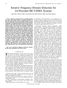
Fig. 1.
15
Performance comparison for Nu = 1 (Nc = 4, Nf = 4).
Fig. 3.
1e+00
25
30
Performance comparison for Nu = 1 (Nc = 32, Nf = 128).
1e+00 AWGN RAKE 2 users RAKE 4 users FDD-ZF 2 users FDD-ZF 4 users FDD-MMSE 2 users FDD-MMSE 4 users
AWGN RAKE 16 users RAKE 32 users FDD-ZF 16 users FDD-ZF 32 users FDD-MMSE 16 users FDD-MMSE 32 users 1e-01
BER
1e-01
BER
20
Eb/No [dB]
1e-02
1e-03
1e-02
1e-03
1e-04
1e-04 0
5
10
15
20
25
30
0
Eb/No [dB]
5
10
15
20
25
30
Eb/No [dB]
Fig. 2. Performance comparison for Nu = 2 and Nu = 4 (Nc = 4, Nf = 4).
Fig. 4. Performance comparison for Nu = 16 and Nu = 32 (Nc = 32, Nf = 128).
resulted in a digital channel model having LRAKE = 100 sample-spaced resolvable replicas. When using FDD, each block of M = 1024 samples is extended by means of a cyclic prefix of 128 samples, so that the channel causes no interference between adjacent blocks. The bit error rate (BER) for the system using RAKE receiver and the systems using FDD with ZF equalization (FDD-ZF) and MMSE equalization (FDD-MMSE) has been evaluated by averaging over 10000 independent channel realizations. Perfect knowledge of the channel parameters has been assumed. In Fig. 1 we show the comparison of BER performance vs Eb /N0 ratio for a single user high data-rate communication: though no multiple access interference has been introduced, the long delay spread of the multipath components cause a remarkable level of self-interference between the replicas of the signals; hence, the RAKE receiver performance is bounded by an irreducible error floor that is clearly visible for high values of Eb /N0 ratio. On the other hand, even if FDD-ZF compensates channel effects, and, therefore, does not show any error floor, the noise enhancement caused by
ZF equalization greatly impairs system performance with a loss of about 10 dB. As it can be clearly seen, FDD-MMSE proves to be the best solution since it does not increase the effects of thermal noise while suppressing self-interference and eliminating the error floor. If we consider a multiuser environment as in Fig. 2, where UWB-IR systems with 2 and 4 users are simulated, the abilities of FDD-MMSE are even more evident. The RAKE receiver is not able to cope with MAI whose effects are increased by the long multipath spread: as a result, performance is greatly impaired and the error floor is evident also for medium to low Eb /N0 values. On the contrary, both FDD strategies are able to restore the orthogonality between users since they perfectly compensates the effects of the channel and FDD-MMSE performance is nearly the same of the single user case. For what concerns the low data-rate scenario, in Fig. 3 the BER performance of the proposed receivers is reported for the single-user case: the high value of the processing gain allows the RAKE receiver to efficiently face the ISI and to be very close to the AWGN bound. While the FDD-ZF performance
171
is plagued as usual by the noise enhancement, the FDDMMSE achieves an excellent performance which is nearly the same of the AWGN bound. Finally, in Fig. 4 we report the results of the proposed receiver for the low data-rate multiuser environment. In particular, UWB-IR systems with 16 and 32 users are simulated which correspond to a half loaded and a fully loaded system, respectively. While the RAKE receiver is impaired by the loss of orthogonality between the users due to the IPI, both the FDD strategies show excellent MAI and self-interference suppression capabilities: once again the FDDMMSE performance is remarkable, also for the fully loaded system. VI. C OMPLEXITY C ONSIDERATIONS For what concerns the complexity involved in the receiver which have been considered and tested, the RAKE receiver appears to be the most simple since its computational load is proportional to the number of multipath components that have to be discerned in the receiver. Both FDD detectors are characterized by higher complexity. However, if we use a fast Fourier transform algorithm, the computational load of these detectors is proportional to the number of samples in the frame, i.e., Nw = 2Nc Nf : this value does not seem prohibitive for future implementations. Also the performance of the Analog-to-Digital Converter (ADC) has a deep impact on the choice of the receiver architecture in a digital wireless system. In UWB systems, this phenomenon is enforced by the large operating bandwidth. In IR-UWB systems, high frequency A/D converters allow the implementation of correlation in the digital domain [8] [10] and enable new modulation and multiple-access concepts that exploit pulse shape. On the other hand, lower frequency converters are based on the use of an analog correlation as a front end of the receiver: hence, in this hybrid architecture the sampling rate requirement is relaxed, which ensures the feasibility of digital radio for UWB systems [9]. Both solutions seem to have a promising future since they are particularly in line with the evolution of silicon technologies. More specifically, a system design free of RF components will facilitate system-on-a-chip (SoC) implementation in CMOS, which shrinks as CMOS scales down from 0.18 μm to 0.13 μm and 0.09 μm [13]. The proposed detector relies on a specific reception chain whose front end, after the receiving antenna, is composed by an analog correlator, namely a pulse deshaper, followed by an ADC which provides the samples to form the data-blocks; however, the smallest time interval which is foreseen in the proposed system, i.e., the pulse duration Tw , is equal to 2 ns. Therefore, in order to recover all the information we only need to sample the output of the pulse correlator at 500 MSPS. We are aware that such an architecture is less flexible and that the hybrid receiver will suffer from circuit mismatches and other non-idealities. The effects of these impairments on the performance of the proposed receiver can be taken into account by introducing more sophisticated channel and system models.
VII. C ONCLUSIONS In this paper, an innovative communication scheme for impulse radio ultra-wideband systems has been proposed. The proposed system is based on both the introduction of the cyclic prefix at the transmitter and the use of a frequency domain equalizer at the receiver. The frequency detection approach has been applied considering two different scenarios characterized by low data rate and high data rate services, respectively. Two different detection strategies based on either the ZF or the MMSE criteria have been investigated. The proposed detectors have been compared with the classical RAKE, considering a base station transmitting to several mobile terminals through a severe multipath channel. Simulation results have shown that both the FDD strategies are able to restore the orthogonality between users since they perfectly compensate the effects of the channel. We found that the FDD-MMSE receiver achieves the best performance for any configuration of active terminals, and appears to be well suited for applications in the indoor wireless environment, both for low data rate and high data rate services. R EFERENCES [1] M. Z. Win and R. A. Scholtz, “Impulse radio: How it works,” IEEE Commun. Lett., vol. 2, no. 2, pp. 36–38, Feb. 1998. [2] T. Brown, K. Schwieger, E. Zimmermann, W. Malik, D. Edwards, L. Ouvry, and I. Oppermann, “Ultra wideband: Technology and future perspectives, v3.0, march 2005, Wireless World Research Forum (WWRF) White Paper.” [3] D. Porcino and W. Hirt, “Ultra-wideband radio technology: potential and challenges ahead,” IEEE Commun. Mag., vol. 41, no. 7, pp. 66–74, Jul. 2003. [4] J. D. Choi and W. E. Stark, “Performance of ultra-wide band communications with suboptimal receivers in multipath channels,” IEEE J. Select. Areas Commun., vol. 20, no. 9, pp. 1754–1766, Dec. 2002. [5] S. U. H. Qureshi, “Adaptive equalization,” Proc. IEEE, vol. 73, no. 9, pp. 1349–1387, Sept. 1985. [6] D. Falconer, S. L. Ariyavisitakul, A. Benyamin-Seeyar, and B. Eidson, “Frequency domain equalization for single-carrier broadband wireless systems,” IEEE Commun. Mag., vol. 40, no. 4, pp. 58–66, Apr. 2002. [7] D. Cassioli, M. Z. Win, and A. F. Molisch, “The ultra-wide bandwidth indoor channel: From statistical model to simulations,” IEEE J. Select. Areas Commun., vol. 20, no. 6, pp. 1247–1257, Aug. 2002. [8] W. Namgoong, “A channelized digital ultrawideband receiver,” IEEE Trans. Wireless Commun., vol. 2, no. 3, pp. 502–510, May 2003. [9] R. Harjani, J. Harvey, and R. Sainati, “Analog/RF physical layer issues for UWB systems,” in Proc. of the 17th IEEE International Conference on VLSI Design (VLSID04), Jan. 2004, pp. 941–948. [10] C. J. L. Martret and G. B. Giannakis, “All-digital impulse radio with multiuser detection for wireless cellular systems,” IEEE Trans. Commun., vol. 50, no. 9, pp. 1440–1450, Sept. 2002. [11] M. Z. Win and R. A. Scholtz, “On the robustness of ultra-wide bandwidth signals in dense multipath environments,” IEEE Commun. Lett., vol. 2, no. 2, pp. 51–53, Feb. 1998. [12] ——, “Ultra-wide bandwidth time-hopping spread-spectrum impulse radio for wireless multiple-access communications,” IEEE Trans. Commun., vol. 48, no. 4, pp. 679–691, Apr. 2000. [13] L. Yang and G. B. Giannakis, “Ultra-wideband radio technology: potential and challenges ahead,” IEEE Signal Processing Mag., vol. 42, pp. 26–54, Nov. 2004.
172