The finite difference frequency domain method for the eigenanalysis of open periodic structures C. S. Lavranos1, P. C. Theofanopoulos1, K. Zoiros1, G. Granet2 and G.A. Kyriacou1 1
Democritus University of Thrace, Department of Electrical & Computer Engineering, Xanthi, GREECE,
[email protected] 2 Clermont Université, Université Blaise Pascal, Institut Pascal, Clermont-Ferrand, France
Abstract—The eigenanalysis of periodic stuctures is presented herein by extending our previous two – dimensional curvilinear frequency domain finite difference domain (FDFD) toward the eigenanalysis of open/radiating periodic structures. Initially, the open/radiating structures are simulated using the Perfectly Matched Layer (PML), while later Mur’s Absorbing Boundary Conditions (ABC) will be introduced within the FDFD formulation. In parallel, the periodicity of the structure is accounted through the enforcement of Periodic Boundary conditions (PBC) within the FDFD formulation. The periodicity can be either in one or in two dimensions, while out of plane propagation is assumed along the third dimension with propagation constant different from zero. Index Terms— Open – radiating structures, ABC, PML, periodic eigenanalysis, finite difference, frequency domain, anisotropic materials.
I.
INTRODUCTION
The present effort aims at the eigenanalysis of openradiating periodic structures. Thus, the scope of that work is twofold. Initially, the numerical solution of the eigenvalue problems for open waveguide structures loaded with anisotropic materials constitutes one of the most challenging problems of computational electromagnetism. Due to the difficulty of the problem limited number of articles has been published on this subject, e.g. [1-2]. In these works numerical methods like the Finite Element or the Finite Difference method have been used in conjunction with proper Absorbing Boundary conditions (ABC) in order to confine the solution domain to a finite area. There are two main kinds of ABCs found in the literature. The first is the straightforward wave absorbing method. The boundary wave field values are usually calculated by some approximations of one-way wave equations. The method can be implemented in both the time domain [3] and the frequency domain [4]. In this case, the absorption effects are greatly dependent on the approximations of the equation used and the incident angle of the wave field. The most important ABC method is Mur’s Absorbing Boundary conditions, [5]. The second category is based on attenuation layers, with most popular representative the PML method [6]. This method modifies the wave equations by introducing the damping factor to absorb the outgoing waves. In this scheme perfect absorptions for any incident wave are expected. However, the utilization of PMLs for domain truncation in open structure eigenproblems is
proved problematic as it causes the occurrence of spurious solutions, also called “Berenger modes”, [1,6]. On the other hand the study of wave propagation through periodic band gap structures and their unique electromagnetic features is of main interest nowadays. These features enabled the development of novel metamaterials and were exploited in frequency selective surfaces, phased arrays and numerous electromagnetic bandgap applications, [7, 8]. The effort toward the analysis and design of such structures is almost exclusively directed toward the deterministic problem solution (source driven). Even though this analysis served as a very useful tool, it does not offer the required physical insight, to devise novel structures. Besides, there has been a considerable interest in the computational techniques of wave propagation through frequency-dependent or dispersive materials, like ferrites or multiferroics, which ask for numerical techniques handling materials with strong frequency variation of either permittivity or permeability tensors. The eigenanalysis of these structures reveal their physical behavior. Also, resulting eigenfunctions can be exploited to devise novel features and enable multifunctionality of periodic structures. This work elaborates exactly on structures periodic in one transverse dimension and open-radiating from the other or periodic in both transverse dimensions. Particular attention is devoted to the case of anisotropic media loading, especially ferrites. Band gap phenomena are examined, while non – reciprocal characteristics are under investigation. II.
FINITE DIFFERENCE METHOD REVIEW
The Finite Difference method (FD) is usually formulated in time or in frequency domain, namely, the Finite Difference Time Domain method (FDTD) and the Finite Difference Frequency Domain method (FDFD). In the FDTD method a deterministic problem is formulated where the structure is excited by an impulse (or short pulse) source located at specific location. A Fourier transform is then employed and the eigenvalues are identified at minimum resonance, since they occur at transverse resonance assuming a specific excitation. However, the transverse resonance may be missed if the excitation is not properly placed. In addition, it has limitation in resolving degenerate modes (modes that exhibit the same transverse resonance). On the other hand, finite-difference frequency-domain approaches are more suitable for solving eigenvalues problems either for periodic or for open structures. Considering the periodic structures, Yang, [8] proposed a
finite-difference frequency-domain scheme based on directly discretizing the Helmholtz’s wave equation in the homogeneous mesh region and matching the field at the central grid point. After that, various two-dimensional (2-D) FDFD algorithms have been developed for band-diagram calculation of periodic structures, usually Photonic Crystals, e.g. [9]. Finally, last year a novel finite-difference frequency-domain (FDFD) algorithm for calculating band diagrams of photonic crystals composed of Debye-type dispersive materials was proposed by Hanif et al., [7]. All of the above works deal with in - plane propagation. Namely, the periodicity is considered along the x and y axis, while the propagation constant along the z axis is equal to zero. There are only few analytical or numerical methods dealing with out of plane propagation, e.g. the semi-analytical method from Arriaga et al. [10]. Besides, most of the FDFD works deal with isotropic materials, while periodic geometries filled with anisotropic materials are of main interest in the recent bibliography, e.g. [11]. Considering now the open-radiating geometries, only a few articles have been published toward this aim, e.g. [1, 2]. In these works the FDFD method in conjunction with the Perfect Matching Layer (PML), [6], technique was employed to confine the solution domain to a finite area. It is well known that the PML technique still suffers from spurious modes. However, it is currently the most powerful technique for the establishment of “transparent” absorbing boundary conditions. Moreover, the anisotropic material PML formulation by Sacks et al., [12], offers the advantage that it does not need any modification of Maxwellian equations and can be implemented as a diagonal permittivity and permeability tensor. III.
CONTRIBUTION OF THE PRESENT WORK
Motivation of the present effort is the combination of FDFD method with Periodic and Open Boundary conditions and is the next step regarding to our previous Eucap work, [13]. Thus, this task is again based on our well established 2-D FDFD method implemented in orthogonal Curvilinear coordinates, [14]. This method applies a global curvilinear discretization of both Maxwell’s curl equations following a central Yee finite differences scheme. In our present work, the eigenvalue problem is formulated and solved for the eigenfrequencies (ω-formulation) of open periodic structures. Namely, the range of wavenumbers is defined and scanned in an iterative solution procedure yielding the Band diagrams and seeking for backward waves and band gaps. The periodicity of the structure is accounted through the enforcement of Periodic Boundary conditions (PBC) within the FDFD formulation. That yields to transversely infinite periodic 2-D geometries. The periodicity can be either in one or in two dimensions, while propagation is assumed along the third dimension. It is important to note that herein the propagation constant along third dimension can be different from zero (out of plane propagation, e.g. [10]). On the other hand, the open/radiating boundaries are modelled using the Perfectly Matched Layer (PML). Being aware the PML yields to a certain type of pseudo modes and also that some finite element techniques were able to accurately solve
eigenproblems using ABCs, we tried to examine this option. For this purpose Mur’s Absorbing Boundary Conditions (ABC) are employed next. IV.
2-D FDFD FORMULATIONS
Open and periodic boundary conditions are applied on both β and ω formulations of our 2-D FDFD method. The basic methodology for both versions of our 2-D FDFD method can be found in our previous work, [13, 14]. This methodology concludes to either a non-deterministic eigenproblem ω formulation as: [A][u]=ω2[u] (1) Or to a non-deterministic β - eigenproblem of the form : (2) L j C u 0 For the first case (1) the eigenfrequency ω is sought for a known propagation constant β, while the opposite occurs in second case (2). The eigenvectors for both cases stand for both the electric and magnetic modal field distributions. V.
IMPLEMENTATION OF BOUNDARY CONDITIONS IN 2DFDFD
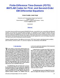
A. Periodic Boundary Conditions A structure with periodicity in the two transverse directions is shown in Fig, 1. In order to formulate the eigenproblem for periodic structures our FDFD method is properly modified. The periodicity is accounted through periodic boundary conditions (PBC) on the unit cell periodic surfaces in order to mimic the infinite periodicity in both directions. For that case, a unit cell is simulated, where, for clarification reasons, the boundary edges are characterized as “master” and “slave” as shown in Fig. 1.
Structure loaded with anisotropic media Fig. 1. Cross section of a unit periodic cell
Every electric or magnetic component on the Slave Edges is correlated with the corresponding electric or magnetic component on the Master Edges by using the equation: A slave A master e jΔφ , where Δφ β L
(3)
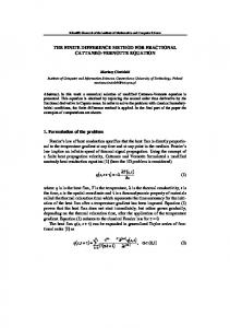
where β stands for the phase constant and L for the cell period. In order now to examine all possible modes, theoretically we have to change the phase constants values from –π to +π. However, due to symmetric and periodic properties, we only have to find Bloch mode solutions in the irreducible Brillouin zone for the corresponding geometry rectangular lattice, [7,8, 11]. Two characteristic examples are shown in Fig. 2. For a structure which contains isotropic materials the zone is the triangular region with corners at Γ, M, X as shown in Fig. 2a, [7]. On the other hand for a structure containing anisotropic materials, like dielectrics with a symmetric permittivity
tensor, the band structure has to be calculated on a larger irreducible Brillouin zone path, as shown in Fig. 2b, namely: ΓMXΓX’MΓX’M’ΓM’X’’Γ, [11]. However, in some cases including Ferrite materials the half cell path may be inappropriate due to asymmetry non – reciprocal reasons. For that case, the whole ΓMXΓX’MΓM’X’ΓX’’M’ΓM’’X’’ΓX’’’M’’Γ’’’X’’’ΓM’X’’ path should be scanned, as shown in Fig. 2c [9].
(a)
(b)
(c)
Fig. 2. Brillouin zones for (a) isotropic and (b,c) anisotropic structures
B. Open Boundary Conditions
field at the radiating boundary must consort with the Helmholtz wave equation: 2 2 2 2 (6) 2 2 2 2 U 0 z c x y Equation (6) for propagation in the z-direction reads: f f ω2 (7) L=D2x +D 2y -β 2 + 2 where Df i = i i 1 c dh Equation (7) can be separated in operators that express the wave propagation along the positive and the negative direction on both transverse axes as follows: Dy2 Dz2 2 i 2 2 L Dx2 Dy2 Dz2 2 Dx2 2 (1 ) 2 c c c2 i i Dx (1 S x2 ) Dx (1 S x2 ) Lx Lx (8) c c The Taylor’s expansion for the square root is exploited:
(1 S x2 ) 1 For the implementation of open - radiating boundary conditions two methods are used. Initially, the Perfectly Matched Layer approach, [1, 6], is used as shown in figure 3. In this method the discretized structure is surrounded by an extra absorption layer, Fig. 4, composed by material with permittivity and permeability tensors set as, [1]:
ηe [ε]=ε 0 0 0
0 -1
ηe 0
0 0 ηe
ηm [μ]=μ 0 0 0
0 -1
ηm 0
0 0 ηm
where ηe,m=1-jζe,m with ζe=(σe/ωεo) and ζm=(σm/ωµo). The electric conductivity in the PML is assigned, [1], as
(n+1)ε 0 c y σ u =σ m ( )n where σ m = lnR th d 2d
(5)
where d is the PML thickness, σm is the maximum electrical conductivity at the outer side of the PML and Rth the theoretical Reflection coefficient. Due to the dependence σ u (y) a multilayer PML is constructed. Perfect Matching Layer Empty Space
Structure
operators can be written as, [3]: TABLE I DISCRETIZED OPERATORS
+
y
Fig. 3. Perfectly matched layer implementation
The second proposed method for the implementation of open radiating boundary conditions is the application of Mur’s Absorbing Boundary Conditions (ABC), [5] formulated properly for the application in frequency domain. Initially the
-
i Lx Dx c i Ly Dy c
i c i Ly Dy c Lx Dx
These operators are discretized using Mur’s approximation scheme, [5]. Operators along the longitudinal axis-u3, are not considered due to the 2-D FDFD scheme used in the present work, where the analysis is restricted to structures uniform along the propagation direction jβ . u 3
Table I equations are now used to express the field on the appropriate radiating edge where open conditions are needed. These new equations replace the existing equations of the boundary field components on systems (1)-(2). The enforcement of ABC formulation on the β eigenproblem leads to a linear final system, while the implementation of ABC on the ω eigenproblem leads to a new quadratic eigenproblem as follows:
ω 2 [A] ω[B] [C] 0 VI.
PEC
(9)
The same procedure is followed for the calculation of L+y , L-y operators. Keeping first order’s accuracy the
x (4)
1 2 1 4 1 6 S x S x S x ... 2 8 16
(10)
NUMERICAL RESULTS
A. Verification In order to verify our method a comparison was made with already published results, [1, 11]. Initially, the comparison was done for periodically arranged anisotropic dielectric squares, studied by Xie et al, [11] as shown in Fig. 4a. The dielectric squares consist of anisotropic material with dielectric permittivity tensor equal to:
4, 3383 1, 0451 0 (12) [ε ] ε 0 1, 0451 3,1315 0 0 0 1 For this case the in plane propagation was studied, where the Irreducible Brillouin Zone path ΓXMΓX'M'Γ scanned, as shown in Fig. 4b, in order to reveal all the phenomena of the anisotropic media, [11]. ]. The results are shown in Fig. 5. As clearly shown there is a very good agreement between our results and those published in [11]. Fig. 7. Dispersion ispersion diagramm for the open – radiating geometry of Fig. 6
Fig. 4. (a) Cross section of periodic anisotropic dielectric squares surrounded by air. (b) The Irreducible Brilluin zone for the in plane propagation of anisotropic inslusions [11] .
Fig. 5. The band structure for the first few modes of the periodic geometry ]. The vertical vertic axis stands of Fig. 5. Our results are compared with Xie’s [11].
B. Open Periodic Array of Microstrip L Lines Printed on Magnetized FerrIte The motivation of our work was the study of open periodic structures loaded or printed on anisotropic materials materials. Thus, the simulated geometry is an open periodic array of microstrip lines as presented in Fig. 8. The periodicity is along the z – axis, while the in plane propagation is considered as the propagation in the xz plane.
Fig. 8. (a) Open periodic array of microstrip lines. (b) Unit cell: Left and right boundaries are periodic, while the bottom boundary is perfect electric conductor (PEC) and the upper boundary is 10-layered PML enclosed by a PEC wall at its end.. Dimensions are a= a=3.38 mm, b=2.8 mm, c=1.4 mm, d= 0.67mm and e=0.2 mm.
for the normalized frequencies, while the horizontal axis stands for wave numbers in different directions. Γ,X,M, Γ,X',M' are symmetry points in Brillouin zone as shown in Fig. 5b.. The propagation constant allong the z axis is set to be zeroo in order to achieve in plane propagation.
In order now to verify the application of Absorbing Boundary conditions, an open - radiating multi conductor microstrip line, initially simulated by Hwang, [1], is simulated. For that case both proposed methods were used. Initially the PML tensor was used, as shown in Fig 6. The results are compared directly with those given by Hwang, [1], and, as shown in Fig. 7, almost excellent agreement is observed. On the other hand, the Mur’s ABC implementation needs more testing and these results will be available at the time of the conference.
Fig. 6. Cross section of an assymetric three – line microstrip lines with PML implementation. h= 0.635mm, w1=0.3 mm, s1=0.2mm, w2=0.6mm, s2=0.4mm, w3=1.3mm, a=3.3mm and εr=9.8.
Fig. 9. Brillouin diagram (phase difference along z-axis vs normalised frequency) for the first modes of thee isotropic case shown in Fig. 8. Our results are compared with [15].
The upper boundary of the simulated unit cell is considered to be open – radiating,, as shown in Fig. 8b 8b. For that case a tenlayered PML, [1,6], is used. Besides, left and right boundaries are periodic, while the bottom boundary is perfect electric conductor (PEC). For all cases the phase difference along the periodical z axis is scanned. Initially, this geometry was simulated and verified for the isotropic case. Namely, the
substrate consists of an isotropic substrate with εr=20 and the results are compared with those by Baccarelli et al, [15]. Very good agreements is observed bserved between our results and those in [15], as clearly shown in Fig. 9, where the first two modes for the in plane propagation are depicted. In this diagram both symmetric direct and reverse modes are shown. Afterwards the substrate is considered as anisotropic and the new geometry is simulated exclusivey with our method. Thus, the t substrate consists of a magnetically saturated ferrite material with εr=12.6, 4πMs=2750Gauss, fm=7.7GHz and linewidth ΔH=225Oe. Also, the DC-bias bias level is ω0/ωm=1, where ω0=γμ0HDC and ωm=γμ0Ms with γ the gyromagnetic ratio. The simulation results are presented in Fig. 10.. The magnetic DC bias is HDC=2700Oe and the in plane (βy=0) propagation pro is again considered. The results for the anisotropic media are depicted in parallel with those for the corresponding isotropic media (εr=12.6). As it is expected, the results for the isotropic media mimic the results presented in Fig. 9. Again symmetric direct and reverse modes are shown, as well as a clear electromagnetic band gap for the he second mode. The anisotropy moves the dispersion curves for the second mode and decreases that electromagnetic band gap. gap The study for different ferent ferrite bias may offer results useful for the design of tuneable Frequency Selective Surfaces (FFS) and other othe microwave applications. More results including open periodic geometries simulated with both PML and Mur’s ABC will be presented in the EUCAP 2015 Conference.
funds nds through the Operational Program "Education and Lifelong Learning" of the National Strategic Reference Framework (NSRF) - Research Funding Program: THALES.. Investing in knowledge society through the European Social Fund.
REFERENCES [1]
[2]
[3] [4]
[5]
[6]
[7]
[8]
[9]
[10] Fig. 10. Brillouin diagram (phase difference vs normalised frequency) for the first two modes of the anisotropic isotropic case shown in Fig. 8.
[11]
VII. CONCLUSIONS
[12]
An open periodic finite difference frequency domain method is formulated for open transversely periodic structures possibly including g printed antenna arrays loaded-printed loaded on anisotropic substrate. The open boundaries are simulated using the Perfectly Matched Layer (PML),, while the periodicity of the structure is accounted through the enforcement of Periodic Boundary conditions (PBC) within the FDFD formulation. The accuracy of the method has verifiedd with already published results for isotropic geometries, while novel results concerning anisotropic geometries were also presented. ACKNOWLEDGMENT This research has been co-financed financed by the European Union (European Social Fund – ESF) and Greek national
[13]
[14]
[15]
J-N Hwang, “A compact 2-D D FDFD method for Modeling Microstrip Structures With Nonuniform Grids and Perfectly Matched Layer” IEEE Trans. Vol. MTT-53, 53, No 2, pp. 653 653-659,Feb 2005. T. Tischler and W. Heinrich, “The perfectly matched layer as lateral boundary in finite-difference transmission transmission-line analysis,” IEEE Trans. Vol. MTT-48, No12, pp. 2249-2253, 2253, Dec 2000. Engquist B and Majda A “Absorbing boundary conditions for numerical simulation of waves” Math. Comput Comput. vol. 31 pp. 629–651, 1977 Pratt R G, “Frequency-domain domain elas elastic wave modeling by finite differences: a tool for crosshole seismic imaging ” Geophysics , vol. 55, pp. 626–632, 1990 G. Mur, “Absorbing boundary conditions for the finite finite-difference approximation od the time-domain domain electromagnetic fields equations”, IEEE Transactions On Electromagnetic Combatibility, vol. 23, no. 4, pp. 377 – 382, Nov. 1981. J-P. P. Berenger, “A perfectly matched layer for the absroption of electromagnetic waves”, J. Comput. Phys., vol. 114, no. 1, pp. 185 185-200, 1994 A. G. Hanif, T. Arimaa and T. Uno, “Finite “Finite-Difference FrequencyDomain Algorithm for Band-Diagram Diagram Calculation of 22-D Photonic Crystals Composed of Debye Debye-Type Dispersive Materials ,” IEEE Antennas and Wireless Propagation Letters, vol. 11, pp.41 pp.41-44, 2012. H . Y. D. Yang, “Finite te difference analysis of 22-D photonic crystals,” IEEE Trans. Microw. Theory Tech., vol. 44, no. 12, pp. 2688 2688–2695, Dec. 1996. Y. Chiang, Y. Chiou and H. Chang, “Finite “Finite-Difference FrequencyDomain Analysis of 2-D D Photonic Crystals With Curved Dielectric Interfaces,” Journal of Lightwave Technology Technology, vol. 26, no. 8, pp. 971976, Apr. 2008. J. Arriaga and B. Meneses, “Band Band structure for the cladding of a hollow core photonic crystal fibre“, “, Investigacion revista Mexicana de fisica, vol. 49, no 4, pp. 335–337, 2003 2003. Huan Xie and Ya Yan Lu, "Modeling two two-dimensional anisotropic photonic crystals by Dirichlet-to to-Neumann maps," J. Opt. Soc. Am. A 26, 1606-1614 (2009). Z. S. Sacks, D. M. Kingsland, R. Lee, and J. J.-F. Lee, “A Perfectly Matched anisotropic absorber bsorber fo for use as an absorbing boundary condition,” ondition,” IEEE Trans. Vol. AP AP-43, pp. 1460–1463, Dec.1995 P.C. Theofanopoulos, C.S. Lavranos, J.N. Sahalos and G.A. Kyriacou, “Backward Wave Eigenanalysis of a Tuneable Two Two-Dimensional Array of Wires Covered with Magnetized Ferrite”, Eucap 2014, 8th European Conference on Antennas and Propagation, pp. 1085 1085- 1089, The Hague, The Netherlands April 2014. C. S. Lavranos, G. A. Kyriacou, “Eigenvalue analysis of curved waveguides employing an orthogonal curvilinear frequency domai domain finite difference method”, IEEE Microwave Theory and Techniques, , vol. 57, no3, pp. 594-611, 611, March 2009. Baccarelli, P.; Burghignoli, P.; Frezza, F.; Galli, A.; Lampariello, P.; Lovat, G.; Paulotto, S., "Modal properties of surface and leaky waves propagating pagating at arbitrary angles along a metal strip grating on a grounded slab," Antennas and Propagation, IEEE Transactions on , vol.53, no.1, pp.36,46, Jan. 2005


![Application of the Finite-Difference Time-Domain Method [PDF]](https://m.moam.info/img/260x300/application-of-the-finite-difference-time-domain-m_647c0a06098a9ef9508b45ca.jpg)


