tion to wideband multipath estimation at millimeter wave bands is studied. Both numerical simulations and channel sounding results at mm-Wave bands are ...
This article has been accepted for publication in a future issue of this journal, but has not been fully edited. Content may change prior to final publication. Citation information: DOI 10.1109/LAWP.2016.2594488, IEEE Antennas and Wireless Propagation Letters 1
Frequency Invariant Uniform Circular Array for Wideband mm-Wave Channel Characterization Fengchun Zhang, Wei Fan and Gert F. Pedersen.
Abstract—A new approach for designing frequency invariant (FI) uniform circular array (UCA) is proposed, and its application to wideband multipath estimation at millimeter wave bands is studied. Both numerical simulations and channel sounding results at mm-Wave bands are provided to demonstrate the effectiveness and improvement of the proposed method in channel parameter estimation over conventional FI UCA method. Index Terms—Frequency invariant beamformer, mm-Wave channel characterization, wideband channel sounding
I. I NTRODUCTION To achieve dramatic improvement in wireless throughput required for next generation wireless systems, the exploitation of currently unused and unutilized spectrum above 6GHz are being proposed [1]. The reasons can be attributed to huge free frequency spectrum and the possibility of implementing massive antenna arrays due to the small wavelength. Although it is difficult to assess possible carrier frequencies and frequency bands over which mm-Wave systems are expected to operate at this stage, it is anticipated that large frequency bands (e.g. up to several GHz) would be required by operators [1]. Accurate characterization of spatial multipath channels is important for the system design and performance analysis of future mm-wave systems. Knowledge of impinging angles of multipath components is essential for beamforming technique in mm-Wave systems. High-gain directional antennas have often been used to collect angle-of-arrival information in channel sounding measurements at mm-Wave bands so far, mainly due to link budget issues, high cost of massive antenna array and lack of wideband array algorithms. However, such measurement systems suffer from time-consuming mechanical steering, low spatial resolution and etc. Frequency invariant beamformers (FIBFs) based on uniform circular arrays (UCAs), which can achieve approximately invariant beam patterns over broad frequency bands and constant beam patterns over the UCA plane, can be utilized for wideband joint angle-of-arrival and delay-of-arrival estimation [2]– [5]. However, it was usually assumed all multipath components are strictly confined to the plane of the UCAs (2D scenarios) , which is never met in practice [3]–[5]. Very few papers have been presented to extend the frequency invariant (FI) characteristics over elevation angles. In [6], a UCA with directional elements of specific radiation patterns 1+cos(φ) (with φ being the azimuth angle in UCA plane) was proposed to prevent the deterioration of beam pattern over elevation angles, though no Fengchun Zhang, Wei Fan, and Gert F. Pedersen are with the APNET section at the Department of Electronic Systems, Faculty of Engineering and Science, Aalborg University, Denmark (email: {fz, wfa, gfp}@es.aau.dk
results were shown. Also, it might be difficult to design such array elements in practice. In [2] and [7], uniform concentric circular arrays (UCCAs) were proposed to form a virtual UCA, where radiation pattern of each virtual element approximates 1+cos(φ). The FI beam patterns around the UCCA plane over a limited elevation region (θ ∈ [80o , 100o ]) were achieved in [7]. However, measurement system utilizing UCCA is more costly, where several UCAs with different radius are required. Furthermore, the presented work lacks practical validation. As far as the authors are concerned, a FIBF algorithm suitable for 3D propagation scenarios, based on UCAs with omnidirectional elements, is clearly missing. Also, the attractive features of FIBF have been mainly investigated in theoretic analysis via numerical simulations, clearly lack of applications in practical channel sounding measurements. To bring this technique from theory to practice, we must ask to what extent the theoretical analysis can be maintained in realistic propagation environments. In this paper, we demonstrate that existing FIBF techniques for UCAs with omni-directional elements discussed in [3] for joint angle and delay estimation is strictly limited to 2D multipath scenarios and would fail in 3D multipath scenarios. To tackle this problem, a novel FIBF algorithm for UCAs with omni-directional elements is proposed and validated in practical measurements. II. P ROBLEM S TATEMENT Assume a UCA with radius r and consisting of P uniformly distributed omni-directional antenna elements, is located on the xy plane. The center of the UCA is located at the origin of the coordinate system. The angular position of the p-th element is ϕp = 2π · (p − 1)/P , p ∈ [1, P ]. The frequency response at the UCA center can be expressed as, H(f ) = [α1 exp(−j2πf τ1 ), ..., αK exp(−j2πf τK )]T , (1) where αk and τk represent the complex amplitude and delay of the k-th path (k ∈ [1, K]), respectively. K is the total number of paths. f ∈ [fL , fU ] is the frequency within the disired range. (·)T denotes the transpose operator. The frequency response vector of the UCA element is: Hel (f ) = A · H(f ),
(2)
where A ∈ CP ×K is the array manifold matrix, with its (p, k)th entry ap,k expressed as: ap,k = exp(j2πf (r/c) sin(θk ) · cos(φk − ϕp )),
(3)
where θk and φk are the elevation and azimuth angle of the kth path, respectively. Elevation angles are measured from the
1536-1225 (c) 2016 IEEE. Personal use is permitted, but republication/redistribution requires IEEE permission. See http://www.ieee.org/publications_standards/publications/rights/index.html for more information.
This article has been accepted for publication in a future issue of this journal, but has not been fully edited. Content may change prior to final publication. Citation information: DOI 10.1109/LAWP.2016.2594488, IEEE Antennas and Wireless Propagation Letters 2
exp(jβ cos γ) =
∞ X
j n Jn (β) · exp(jnγ),
(4)
Beam pattern of the FIB UCA for different θ 0 −10
Power [dB]
z axis, and azimuth angles are measured counter-clockwise from the x axis on the xy plane. The main objective is to detect path parameters {αk , τk , φk } with arbitrary θk present. Below, we demonstrate that the reported FIBF UCA actually only works for 2D scenarios, i.e. θk = 90o for k ∈ [1, K]. As demonstrated in [3], [8], the conventional beamformer for UCA is frequency variant, which in turn generates joint high sidelobes in delay and angle domains. To acheive the FIBF, we need to convert the element response to phase mode response by applying the Jacobi-Anger expansion [3]:
−20
θk = 90o
−30
θk = 95o
−40
θk = 120o
−50 −150
−100
−50
0
φ− φk [o]
50
100
150
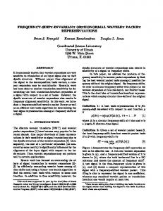
k (f, φ − φ ) for the existing FIBF with θ = Figure 1. The beam pattern vF k k 90o , θk = 95o and θk = 120o . The simulation frequency is f = 30 GHz.
n=−∞
where Jn (·) is the Bessel function of the first kind with order n. (3) can be then expressed as: ∞ X
ap,k =
j n Jn (2πf r
n=−∞
sin(θk ) ) · exp(jn(φk − ϕp )) (5) c
The phase mode response can be expressed as 1 Gm (f ) · E · Hel (f ) P 1 Gm (f ) · E · A · H(f ) = P = Gm (f ) · v m · H(f ), m ∈ [−M, M ] (6)
ˆ m (f ) = H
where E = [exp(jmϕ1 ), ..., exp(jmϕP )], and Gm (f ) is a compensation filter that will be discussed later and M is the highest phase mode. v m ∈ C1×K is a vector, according to (2) and (6), with its k-th element as: k vm (f ) =
P 1 X exp(jmϕp ) · ap,k P p=1
(7)
k vm (f ) can be approximated by the first dominant term [3], k vm (f ) = j m Jm (2πf (r/c) sin(θk )) · exp(jmφk )
where w = [exp(−j(−M )φ), ..., exp(−j(M )φ)]T /(2M + 1) is the weighting vector. (9) can be simplified as,
where v F (f, φ) ∈ C vFk (f, φ)
(10)
is a vector with its k-th element:
M X exp(−jm(φ − φk )) = 2M + 1 m=−M
(11)
· j m Jm (2πf (r/c) sin(θk )) · Gm (f ) (10) can be further written as: HF (f, φ) =vFk (f, φ) · αk exp(−j2πf τk ) X + vFi (f, φ) · αi exp(−j2πf τi ), i6=k
(12)
sin(M + 0.5)(φ − φk ) 1 2M + 1 sin(0.5(φ − φk ))
(13)
As demonstrated by simulation results in [3], vFk (φ) significantly outperforms classical beamformer when all paths are strictly limited to the UCA plane, as a frequency-invariant beam pattern with much lower sidelobes can be achieved. b) 3D multipath scenario: If Gm (f ) = 1/[j m Jm (2πf r/c)] is still selected for 3D multipath scenarios, according to (11), we have
vFk (f, φ) =
ˆ −M (f ), ..., H ˆ 0 (f ), ..., H ˆ M (f )]T , (9) HF (f, φ) = wT · [H
1×K
vFk (f, φ) = vFk (φ) =
(8)
Converting the phase mode to angle domain, we have
HF (f, φ) = v F (f, φ) · H(f ),
To obtain path parameters {αk , τk , φk } for k ∈ [1, K], we need to ensure: k i • For φ = φk , we have vF (f, φk ) = 1 exists and vF (f, φk ) approaches 0 for i 6= k; k • For φ 6= φk , we have vF (f, φ) approaches 0; k • vF (f, φ) should be frequency independent. a) 2D multipath scenario: If all K multipath components are restricted to the UCA plane (i.e. θk = 90o , for k ∈ [1, K]), by selecting the compensation filter Gm (f ) = 1/[j m Jm (2πf r/c)] in (11), as discussed in [3], we have,
M X exp(−jm(φ − φk )) 2M + 1
m=−M
(14)
j m Jm (2πf (r/c) sin(θk )) · j m Jm (2πf (r/c)) From (14), we can see that the beam pattern of vFk (f, φ) becomes frequency dependent for θk 6= 90o . The beam patterns of FIBF with θk = 90o , 95o and 120o are shown in Figure 1. A peak at φ = φk does not occur with θk = 95o and 120o . Worse still, vFk (f, φ) does not approach 0 at φ = φi for i 6= k, i ∈ [1, K]. That is, the other paths in the UCA plane cannot be detected, since their beam patterns would be significantly affected by the interfering power pattern of vFk (f, φ). The reason is that Bessel functions Jm (·) are very sensitive to θk and m, for given f , as shown in Figure 2. Applying Jm (2πf (r/c)) to approximate Jm (2πf (r/c) sin(θk )) would cause large errors, which vary widely with different m and θk . As a summary, the reported FIBF algorithm for the UCA would fail to detect any path if there exists a path that is not strictly in the UCA plane. This critical assumption, however, is never met in practice.
1536-1225 (c) 2016 IEEE. Personal use is permitted, but republication/redistribution requires IEEE permission. See http://www.ieee.org/publications_standards/publications/rights/index.html for more information.
This article has been accepted for publication in a future issue of this journal, but has not been fully edited. Content may change prior to final publication. Citation information: DOI 10.1109/LAWP.2016.2594488, IEEE Antennas and Wireless Propagation Letters 3
Bessel functions, Mode 0
Mode amplitude [dB]
Mode amplitude [dB]
−20 −30
θk = 90 o θk = 95 o θk = 120 o ˆ m| |2/ G
−40 −50 −60 28
28.2
28.4
28.6
28.8
29
29.2
Frequency [GHz]
29.4
29.6
29.8
30
k Figure 3. The beam pattern vˆF,3D (f, φ) with θk = 90o (left), θk = 95o (middle) and θk = 120o (right) for f = 28 − 30 GHz.
Bessel functions, Mode 80
−20 −30 −40 −50 −60 28
28.2
28.4
28.6
28.8
29
29.2
Frequency [GHz]
29.4
29.6
29.8
30
Figure 2. Mode analysis of Bessel function Jm (2πf (r/c) sin(θk )) for m = 0 with θk = 90o , θk = 95o and θk = 120o for mode 0 and mode 80.
III. P ROPOSED FIBF FOR 3D M ULTIPATH SCENARIOS The FIBF technique with existing compensation filter Gm (f ) would fail to work in 3D multipath scenarios, mainly due to the fact that Gm (f ) ∗ j m Jm (2πf (r/c) sin(θ)) = 1 can not be guaranteed for m ∈ [−M, M ], especially when elevation angles θk is typically unknown beforehand in practice. However, if there exists a compensation filter that avoids deep nulls of Jm (2πf (r/c) sin(θ)), approximately independent of ˆ m (f )·Jm (2πf (r/c) sin(θ))−1| would be m and θ, the error |G limited to a large extent. Inspired by this, a novel compensation ˆ m (f ) for FIBF UCA is proposed: filter G 0 1 = 0.5j m (Jm (2πf r/c) − jJm (2πf r/c)), ˆ Gm (f )
(15)
0
where (·) is the differential operator. It is explained in [9] that 0 Jm (x) has the property that when Jm (x) approaches 0, Jm (x) is approximately a maximum and vice versa (except for x → ˆ m (f ) can effectively avoid 0). Therefore, the proposed 1/G ˆ m (f ) is nulls, independent of m and θ. The amplitude of 2/G shown as red dash lines in Figure 2 for illustration purpose. ˆ m (f ) in (11), we have: Replacing Gm (f ) with G
k vˆF,3D (f, φ) =
M X exp(jm(φ − φk )) 2M + 1
m=−M
j m Jm (2πf (r/c) sin(θk )) · ˆ m (f ) 1/G
(16)
k The beam pattern vˆF,3D (f, φ) with θk = 90o , 95o and 120o for 28-30 GHz are shown in Figure 3, respectively. Unlike the k existing FIBF , a peak exists at φ = φk for vˆF,3D (f, φk ) with different θk values with the proposed FIBF. Beam patterns of the proposed FIBF deteriorate as θk gets larger, with wider and more attenuated main beam, though. The proposed FIBF is not very sensitive to elevation angles, with similar FI beam pattern achieved for θk = 90o and 95o , as shown in Figure 3. k vˆF,3D (f, φ) also approaches 0 as φ gets away from φk .
However, the proposed FIBF suffers from a sidelobe around φ = φk ± 180o , with −25 dB lower than the peaks for paths close to the UCA plane (e.g., θk = 90o and θk = 95o ) and −10 dB for the path with θk = 120o , as shown in ˆ m (f ) · Figure 3. This is due to the remaining error in |G Jm (2πf (r/c) sin(θ)) − 1|, though it is greatly reduced by ˆ m (f ). As shown in (13), v k (φ) is a real value, introducing G F independent of frequency. This is, however, not the case k k with the proposed vˆF,3D (f, φ). The phase of vˆF,3D varies approximately linearly over frequency and the slope depends on φ angles. The slope is 0 at φ = φk and increases as φ deviates from φk , with its maximum at φ = φk ± π. Due to this, a positive shift would be introduced to the sidelobes in delay domain, with a maximal delay shift at φ = φk ± π for the k-th path for k ∈ [1, K]. This effect will be further demonstrated in measurement results in Section IV. IV. M EASUREMENT VALIDATION In this section, the proposed FIBF for UCA is validated in practical measurements, via comparing measured results with that of a rotational horn. A description of the measurement campaign was given in [8], and hence is only outlined here. The measurements performed in a simple line of sight (LOS) scenario in a large empty room were used in this paper. A vertically polarized wideband Biconical antenna was used as the transmitter (Tx), while two types of vertically polarized antennas (a Biconical and a horn antenna) were used as the receivers (Rx), respectively. A vector network analyzer (VNA) connected to the Rx antenna. In the first measurement, a horn antenna was mounted on the rotation center of the turntable. In the second measurement, a virtual UCA with r = 0.5 m was realized by mounting a Biconical antenna on a positioning turntable. We obtained P = 720 positions by automatically repositioning the Rx antenna at uniform angles for both measurements. At each position, a frequency sweep was performed for frequency band 28−30 GHz with N = 750 frequency samples. Note that virtual array is desirable for channel characterization purpose, as mutual coupling effect between antenna elements is not present. The measured power-angle-delay profiles with the rotational horn at the Rx side can be directly obtained, via performing inverse Fourier transform of the recorded channel frequency responses for each rotation. As we can see in Fig. 4, the LOS path is dominant and only a few specular paths due to LOS propagation and specular reflections (up to 2 orders) were identified. The measured results with rotational horn antenna
1536-1225 (c) 2016 IEEE. Personal use is permitted, but republication/redistribution requires IEEE permission. See http://www.ieee.org/publications_standards/publications/rights/index.html for more information.
This article has been accepted for publication in a future issue of this journal, but has not been fully edited. Content may change prior to final publication. Citation information: DOI 10.1109/LAWP.2016.2594488, IEEE Antennas and Wireless Propagation Letters 4
Figure 4. Measured power-angle-delay profile with rotational horn antenna. Note that the delay is limited to 60 ns to illustrate the main paths. Power is normalized and the power dynamic range is limited to 35 dB.
Figure 6. Identified path trajectories in the measurements. Note that path 2 and path 9 correspond to a ground reflection and a ceiling reflection, respectively, while the other paths are on the UCA plane.
Figure 5. Measured power-angle-delay profile with the virtual UCA, ultilizng the proposed FIB-UCA technique.
suffers from low spatial resolution, as expected. For the virtual UCA measurement, the UCA element frequency response vector Hel (f ) in (2) is directly recorded. We can obtain the ˆ m (f ) in (6) by applying the proposed phase mode vector H ˆ Gm (f ) in (15). The measured power-angle-delay profile can then be obtained, via performing inverse Fourier transform of HF (f, φ) in (10). As we can see in Fig. 5, the same paths (as numbered) are identified with two different measurements. The measured results demonstrate that the proposed algorithm works as expected. The measured results with the proposed FIB UCA, though suffering from the sidelobe of the path 1 (around 0o ), are with excellent resolutions in delay and angle domains. The sidelobe is shifted in delay domain compared to path 1, as explained in Section III. The trajectories of the multipath components can be obtained by relating the measured angle and delay information to the room geometry, as shown in Figure 6. The identified path trajectories based on estimated path parameters are consistent with the room geometry and ray optics. Note that the existing FIB for the UCA fails to detect any multipath component, not even the LOS component, as some paths (e.g. path 2 and 9), though weak in power, are not strictly confined in the UCA plane. V.
CONCLUSION
This paper presents a novel FIBF for UCA with omnidirectional elements to estimate wideband path parameters at
mm-Wave bands in practical 3D scenarios. Unlike the existing FIBF technique for UCA that is strictly limited to 2D multipath scenarios, the proposed FIBF for UCA works for general 3D multipath scenarios. Measurement results demonstrated that the proposed algorithm can accurately estimate path parameters with spatial and delay resolutions and help identify the path trajectories. The main problem with the proposed algorithm is that sidelobes around φk ± π (k ∈ [1, K]) exist. Sidelobe suppression techniques could be investigated to improve the results in future work, based on the known characteristics of sidelobes as shown in the paper. R EFERENCES [1] M. Marcus, “5g and "imt for 2020 and beyond" [spectrum policy and regulatory issues],” Wireless Communications, IEEE, vol. 22, no. 4, pp. 2–3, August 2015. [2] S. Chan and H. Chen, “Uniform concentric circular arrays with frequencyinvariant characteristics - theory, design, adaptive beamforming and doa estimation,” Signal Processing, IEEE Transactions on, vol. 55, no. 1, pp. 165–177, Jan 2007. [3] C. Gentile, A. Braga, and A. Kik, “A comprehensive evaluation of joint range and angle estimation in ultra-wideband location systems for indoors,” in Communications, 2008. ICC ’08. IEEE International Conference on, May 2008, pp. 4219–4225. [4] M. S. Hossain, G. N. Milford, and M. C. Reed, “Efficient robust broadband beamforming using circular antenna arrays,” InCommunications and Information Technologies (ISCIT), 2012 International Symposium on (pp. 746-751). IEEE., 2012. [5] Y. Yang, C. Sun, and C. Wan, “Theoretical and experimental studies on broadband constant beamwidth beamforming for circular arrays,” In OCEANS 2003. Proceedings (Vol. 3, pp. 1647-1653). IEEE., 2003. [6] T. Rahim and D. Davies, “Effect of directional elements on the directional response of circular antenna arrays,” Microwaves, Optics and Antennas, IEE Proceedings H, vol. 129, no. 1, pp. 18–22, February 1982. [7] B. Liao, K.-M. Tsui, and S.-C. Chan, “Frequency invariant uniform concentric circular arrays with directional elements,” Aerospace and Electronic Systems, IEEE Transactions on, vol. 49, no. 2, pp. 871–884, APRIL 2013. [8] W. Fan, I. Carton, J. Ø. Nielsen, K. Olesen, and G. F. Pedersen, “Measured wideband characteristics of indoor channels at centimetric and millimetric bands,” EURASIP Journal on Wireless Communications and Networking, vol. 2016, no. 1, pp. 1–13, 2016. [9] D. Davies, “Circular arrays,” The handbook of antenna design, vol. 2, pp. 299–329, 1983.
1536-1225 (c) 2016 IEEE. Personal use is permitted, but republication/redistribution requires IEEE permission. See http://www.ieee.org/publications_standards/publications/rights/index.html for more information.