The PIV system is a LaVision Flowmaster Planar Time Resolved system that allows for two- ... The laser is a Litron Lasers Ltd. LDY303He Nd:YLF laser with a.
50th AIAA Aerospace Sciences Meeting including the New Horizons Forum and Aerospace Exposition 09 - 12 January 2012, Nashville, Tennessee
AIAA 2012-0451
Frequency Locking and Vortex Dynamics of an Acoustically Excited Bluff Body Stabilized Flame
Downloaded by GEORGIA INST OF TECHNOLOGY on December 16, 2015 | http://arc.aiaa.org | DOI: 10.2514/6.2012-451
Benjamin Emerson1, Jacqueline O’Connor1, David Noble2, Tim Lieuwen3 Georgia Institute of Technology, Atlanta, GA, 30318
This paper presents measurements of the forced response of a bluff body stabilized flame. The nonreacting, unforced flow exhibits intrinsic oscillations associated with an unstable, global wake mode. This same global mode persists in the reacting flow at low density ratios, but disappears at high flame density ratios where the flow is dominated by the convectively unstable shear layers. The flow responds quite differently to forcing in these two situations, exhibiting a roughly linear input-output character in the convectively unstable regime, but exhibiting nonlinear behavior, such as frequency locking, during global mode oscillations. In this work, a reacting bluff body wake is subjected to harmonic, longitudinal, acoustic forcing, providing a symmetric disturbance. This experiment is conducted at several density ratios as well as different spacing between the forcing frequency and global mode frequency. As the spacing between these frequencies is narrowed, the wake response is drawn away from the global mode frequency and approaches (and eventually locks-into) the forcing frequency. This observation seems to be linked to the spatial distribution of vorticity fluctuations, as well as the symmetry of the vortex shedding. For example, for large spacing between the forcing and global mode frequencies, there is significant response at the forcing frequency in the shear layers, but little response is observed along the flow centerline (which itself exhibits strong oscillations at the global mode frequency). This seems to be due to the symmetry of vortical structures that are shed at the forcing frequency. For small spacing between these frequencies, however, the vortices shed symmetrically at the forcing frequency, but quickly stagger into an asymmetric configuration as they convect downstream. For such cases, we observe a strong response of the wake at the forcing frequency. The axial distance required for such staggering to occur is a function of the spacing between the forcing frequency and natural frequency, the flame density ratio, and the intensity of the forcing.
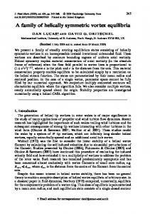
Nomenclature A D
ṁ Ne Ns Re StD T U c f j k rU,L
= = = = = = = = = = = = = =
flow cross-sectional area bluff body diameter mass flowrate number of ensembles number of samples Reynold’s number, UlipD/ν Strouhal number, fD/Ulip temperature time-averaged axial velocity modal wave propagation speed frequency, Hz any integer wavenumber correlation coefficient between upper and lower flame edge positions
1
Graduate Research Assistant, School of Aerospace Engineering, 270 Ferst Dr, AIAA Student Member. Research Engineer, School of Aerospace Engineering, 270 Ferst Dr, AIAA Member. 3 Professor, School of Aerospace Engineering, 270 Ferst Dr, AIAA Associate Fellow. 1 American Institute of Aeronautics and Astronautics 2
Copyright © 2012 by Benjamin Emerson, Jacqueline O'Connor, David Noble, Tim Lieuwen. Published by the American Institute of Aeronautics and Astronautics, Inc., with permission.
t v
= time = instantaneous transverse velocity
β Ω ζL ζU ν ρ φ ω
= = = = = = = =
backflow ratio, -U(y=0)/U(y=∞) unsteady vorticity lower flame edge position upper flame edge position kinematic viscosity gas density equivalence ratio frequency, rad/s
0 b i in lip max ref u
= = = = = = = =
zero group velocity burned imaginary component inlet bluff body trailing edge lip maximum reference velocity unburned
’ f n r
= = = =
unsteady component forcing natural response
Downloaded by GEORGIA INST OF TECHNOLOGY on December 16, 2015 | http://arc.aiaa.org | DOI: 10.2514/6.2012-451
Greek Characters
Subscripts
Superscripts
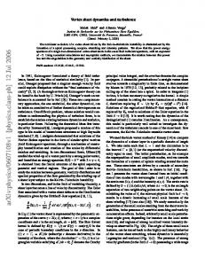
I. Background The unsteady flow fields in reacting bluff body flows are often dominated by large scale coherent structures, embedded upon a background of acoustic waves and broadband fine scale turbulence. These large scale structures play important roles in such processes as combustion instabilities 1-3, mixing and entrainment, flashback, and blowoff4. These structures arise because of underlying hydrodynamic instabilities of the flow field 5. This paper extends recent work which characterized the effects of the flame upon the absolute and convective instability characteristics of the flow6-9. Here we analyze the effects of harmonic forcing upon this flow. The response of the flame and flow to harmonic forcing is motivated by the combustion instability problem10, where heat release oscillations couple to natural acoustic modes of the combustion chamber and lead to large amplitude, narrowband tones. As shown in Figure 1, there are two key flow features downstream of the bluff body in high Reynolds number flows; these include the separating free shear layers11 and the wake, both of which strongly influence the flame. These two flow features are discussed next.
2 American Institute of Aeronautics and Astronautics
Downloaded by GEORGIA INST OF TECHNOLOGY on December 16, 2015 | http://arc.aiaa.org | DOI: 10.2514/6.2012-451
a)
b)
Figure 1. a) Schematic of non-reacting flow past a bluff body at ReD = 10,000. Reproduced from Prasad and Williamson12 b) Instantaneous streamlines from current experiment, for non-reacting wake behind v-gutter at Ulip = 50 m/s, produced from PIV measurement The separated shear layer is convectively unstable due to the Kelvin-Helmholtz mechanism for ReD ~ 1200 12, leading to shear layer rollup into tightly concentrated vorticity. In most practical configurations, the flame lies nearly parallel to the flow and, thus, almost directly in the bluff body shear layer for high velocity flows. The separating vorticity sheet on both sides of the bluff body rolls up, which induces a flow field that wraps the flame around these regions of concentrated vorticity. In non-reacting flows, the bluff body wake is absolutely unstable, and characterized by large scale, asymmetric rollup of the separating shear layer into staggered vortical structures13, often referred to as the Von Karman vortex street. This instability has a characteristic frequency of12 U lip f BVK St D (1) D where St D is the Strouhal number. For circular cylinders, St D is independent of Reynolds number ( StD 0.21 ) in the turbulent shear layer, laminar boundary layer regime, ~ 1000 < ReD ~ 200,000 14. Above ReD ~ 200,000 , the boundary layer starts to transition to turbulence and there are some indications that this Strouhal number value changes15-16. Bluff body shape also influences the Strouhal number for the Von Karman vortex street 17. In particular, St D is lower for “bluffer” bodies, i.e., those with higher drag and wider wakes18. For example,
StD ~ 0.18 for a 90 degree “v-gutter” and drops to 0.13 for a sharp edge, vertical flat plate19. These baseline flow stability characteristics are altered by heating the fluid in the wake 20-24, by addition of splitter plates11, and through base bleeding/blowing, to name several examples. Of most interest to this study are wake density ratio effects (due to heating, for example). It has been shown that a sufficiently hot wake relative to the free stream eliminates the absolute instability of the wake, so that the flow’s dynamics are then controlled by the convectively unstable shear layers. For example, Yu and Monkewitz22 performed parallel stability analyses of variable density wakes, characterized by an outer flow with a density, u , and time-averaged velocity, U u , and wake region with density b and velocity U b (see Figure 2). For an inviscid flow with a step jump in properties between the two fluids, they show that the absolute stability boundary depends upon density ratio between the outer flow and the wake, as well as the ratio of reverse flow velocity in the wake to outer flow velocity, , defined below: u b uu
3 American Institute of Aeronautics and Astronautics
(2)
Downloaded by GEORGIA INST OF TECHNOLOGY on December 16, 2015 | http://arc.aiaa.org | DOI: 10.2514/6.2012-451
Figure 2. Sketch of the heated wake problem profile. The convective/absolute stability boundary predicted by their analysis is plotted in Figure 3. For the purpose of this study, only the sinuous (asymmetric) mode stability boundary is plotted, as it is more easily destabilized in wakes than the varicose (symmetric) mode. This plot shows that absolute instability is promoted with lower density ratios, u b , and higher wake reverse flow velocities. For the reacting mixtures considered in this study, the density ratios plotted in the figure are also essentially identical to the flame temperature ratio, Tb Tu . Similar stability calculations have also been performed using more realistic velocity and density ratio profiles, such as hyperbolic tangent profiles and incorporating viscous effects25-26. A particularly significant effect is differences in location of the velocity and density jump in the wake, which can cause the stability boundary in Figure 3 to move significantly.
Figure 3. Dependence of convective/absolute stability limit upon backflow ratio and density ratio, as predicted by 2D parallel flow stability analysis 22 These points have important implications on the effects of a flame on the bluff body flow field, as the density and velocity profiles in Figure 2 are a good first order approximation of a reacting flow profile in a high velocity flow. Indeed, a variety of prior studies have noted fundamental differences in the dynamic character of the flame and/or flow field at different velocity and fuel/air ratio conditions 27-28, particularly under near blowoff conditions29-35 or in flames utilizing highly preheated reactants23, 29, 36. Erickson et al.23 and Emerson et al. 37-38 presented calculated results of flames with various density ratios, showing that a large sinuous flow feature gradually grows in prominence as density ratio across the flame is decreased below values of approximately 2-3. A significant additional observation from the latter study was that the transition to absolute instability did not appear abruptly as the density ratio crossed some threshold value. Rather, the flow intermittently flipped into and out of the sinuous mode in a transitional range of density ratios. The fraction of time that the flow spent in the sinuous flow state and oscillating in a narrowband fashion increased monotonically with decreasing density ratio. These observations are quite significant, as they show that the dominant fluid mechanics in a burner with non preheated reactants, such as lab burners or atmospheric pressure boilers, which have a “high” density ratio, can be very different from those of facilities with highly preheated reactants. For example, stoichiometric methane air flames with reactant temperatures, Tu = 300 and 1000 K have density ratios of 7.5 and 2.6, respectively. Examples of low temperature ratio practical applications include gas turbines, where Tu ~ 700K-900K39, recuperated cycles 4 American Institute of Aeronautics and Astronautics
Downloaded by GEORGIA INST OF TECHNOLOGY on December 16, 2015 | http://arc.aiaa.org | DOI: 10.2514/6.2012-451
where Tin ~1000K-1100K40-41, or applications using vitiated combustion products, such as duct burners used in waste heat boilers downstream of ground power gas turbines42. The implications of this absolute/convective instability distinction are particularly significant in thermoacoustic instability problems, where vortical structures excited by acoustic waves play important roles in the feedback mechanism43. A “convectively unstable” system is quite sensitive to acoustic excitation6. In contrast, an absolutely unstable system is an oscillator – it exhibits intrinsic, self-excited oscillations and does not require external disturbances to persist. In such a self-excited system, the limit cycle behavior may remain independent of the external forcing, may shift in frequency with increasing amplitude of excitation, and/or may monotonically decrease in amplitude with increased forcing amplitude 17, 44-45. In one case, low amplitude acoustic excitation induces a proportional response while in the other it may not. In turn, this has important implications on which type of flow instabilities can be involved in linear combustion instability mechanisms. For example, it suggests that simulating combustion instabilities in simplified lab combustors with high density ratios will lead to completely different acoustic-hydrodynamic stability coupling processes than what may actually be occurring in the low flame density ratio application of interest. The objective of this study is to characterize the unsteady flow evolution of longitudinally forced flames as a function of flame density ratio. The rest of paper is organized as follows. First, we describe the experimental facility in which flame density ratio is monotonically varied across this bifurcation in flow structure at constant Ulip. To do this, it is necessary to highly preheat the reactants to obtain flames that are stable (i.e., well removed from blowoff), yet of low density ratio. This was done by developing a facility capable of vitiating the flow, with independent control of the fuel/air ratio of the two burners. Such a facility is able to achieve broad ranges of flame density ratio. In order for these density ratio sweeps to be conducted at a fixed bluff body lip velocity requires a second, independently controlled air injection source. The ability to control two independent air flows and two independent fuel/air ratios leads to substantial flexibility in operating conditions. Furthermore, great care was taken to stay well away from blowoff boundaries, where additional flame dynamics can occur4, 46-47. Next, we experimentally characterize the unsteady flow evolution as the density ratio is varied at constant Ulip. We observe that a gradual shift in flow structure exists when the flame is operated near the absolute-convective stability limit, and the flame density ratio is swept across this limit. Finally, we investigate the effects of longitudinal acoustic forcing on these low density ratio wakes. We show that the shear layers primarily exhibit oscillations at the forcing frequency and the wake primarily exhibits oscillations at its natural frequency. However, when the flow is either forced sufficiently strongly or sufficiently near the natural wake frequency, the wake oscillations may be drawn away from the wake’s natural frequency, and may even lock-into the forcing frequency. The symmetry of the coherent vortex shedding at the forcing frequency turns out to be related to this lock-in phenomenon.
II. Experimental Facility, Diagnostics, and Testing Procedures The experimental rig, shown in Figure 4, consists of two premixed, methane-air combustors in series. This facility, the bluff body geometries, and the diagnostics are detailed in previous work37-38 and so are only briefly described here. The main components are a vitiator, secondary air and fuel inlets, a flow settling section, acoustic drivers, and the test section. The test section is rectangular with a bluff body spanning the width of the combustor, creating a nominally 2D flow. The aspect ratio of bluff body height to chamber width is 0.15. This combustor has quartz windows for optical access from all four sides. Two different bluff bodies were used in the test section: a 2D ballistic shape and a V-gutter. From here on, the 2D ballistic shape will be referred to as the ballistic bluff body.
Figure 4. Schematic and photograph of the atmospheric pressure, vitiated, bluff body rig
5 American Institute of Aeronautics and Astronautics
Downloaded by GEORGIA INST OF TECHNOLOGY on December 16, 2015 | http://arc.aiaa.org | DOI: 10.2514/6.2012-451
The primary and secondary air and fuel each have their flowrates adjusted individually. This design allows the flame density ratio and bluff body lip velocity to be varied independently in the test section, by adjusting the air flowrate and stoichiometry in the vitiator and test section separately. The test matrix was developed such that primary and secondary air flowrates and primary and secondary equivalence ratios could be adjusted to achieve a variety of density ratios at a fixed velocity. The measured primary air and fuel flowrates as well as the measured temperature just before the test section were recorded. The measured absolute temperature entering the test section was ~25-30% lower than the calculated adiabatic temperature. Bluff body lip velocity was calculated as Ulip=ṁlip/(ρlipAlip). For this lip velocity calculation, the total measured mass flowrate and the flow cross sectional area at the bluff body trailing edge were used. The density for the lip velocity calculation was determined from the temperature measured just before the test section and the gas composition of the secondary air and fuel adiabatically mixed with the equilibrium vitiated gas. An equilibrium gas solver was then used to calculate the adiabatic density ratio across the test section flame. Experimental diagnostics consisted of high speed, line of sight imaging of flame chemiluminescence and particle image velocimetry (PIV). High speed video was captured for the ballistic bluff body only. High speed imaging was performed with a Photron Fastcam SA3 camera to capture chemiluminescence at a 3000 Hz frame rate at a resolution of 512 x 256 pixels. This CMOS camera operates nearly continuously at 3000 Hz. The flame was imaged through a BG-28 filter for CH* chemiluminescence imaging. This filter transmission exceeds 10% for wavelengths between 340 and 630 nm, and peaks at 82% transmission at 450 nm. The flame was imaged from the bluff body trailing edge to approximately nine bluff body diameters downstream. A total of 8029 images were stored in each run. The resulting images were used to quantify flame motion via the transverse position of the top and bottom flame branch edges, ζU(x,t) and ζL(x,t), as a function of axial position and time (see Figure 5). This resulted in time series for edge positions along both flame branches, at each axial position. These time series are Fourier transformed to determine their temporal spectra, given by ζU(x,f) and ζL(x,f).
Figure 5. Coordinate system and instantaneous flame edge position definition from edge tracking, Ulip = 50 m/s, ρu/ρb = 1.7. PIV was conducted for both the ballistic bluff body and the V-gutter at conditions identical to those for high speed video. The PIV system is a LaVision Flowmaster Planar Time Resolved system that allows for twodimensional, high-speed velocity measurements. The laser is a Litron Lasers Ltd. LDY303He Nd:YLF laser with a wavelength of 527 nm and a 5 mJ/pulse pulse energy at 10 kHz repetition rate. The laser is capable of repetition rates up to 10 kHz in each of the two laser heads. The Photron HighSpeed Star 6 camera has a 640x448 pixel resolution with 20x20 micron pixels on the sensor at a frame rate of 10 kHz. In the current study, 2000 PIV image pairs were taken at a frame rate of either 10 kHz or 5 kHz, with 12 s between images for a given image pair. The DaVis 7.2 software from LaVision was used to process the PIV data, performing background subtraction and then calculating the velocity fields. Longitudinal acoustic waves were excited with a pair of 100 Watt speakers. Because the combustor has a limited number of discrete, resonant acoustic frequencies, the flow was driven consistently at a fixed frequency of 515 Hz. Rather than performing a sweep of the forcing frequency, the natural wake frequency of the bluff body was swept by altering the lip velocity. For each condition, three tests were performed: one with no forcing, one with “medium” forcing, and one with “high” forcing. The “medium” and "high" forcing had longitudinal acoustic velocity amplitudes of approximately 4% and 6% of the lip velocity, respectively. In order to ensure the same combustor characteristics for the unforced and forced conditions, these data were taken during the same test runs by allowing the combustor temperature to equilibrate and then to take the data without shutting off the combustor or adjusting any valves. This allowed for flow conditions (e.g., flowrates and equivalence ratios) to be maintained very 6 American Institute of Aeronautics and Astronautics
consistently between the three data sets. This procedure was repeated for all of the density ratios and flow velocities of interest. It is important to note that, for the acoustically forced cases, sampling was performed such that spectral leakage from the forcing frequency would be negligible. This ensures that measurements of dynamics at the global mode frequency are not contaminated by energy leaked from the forcing frequency, even when the two frequencies are close. This was accomplished by setting the forcing frequency, sampling frequency, number of samples and number of ensembles such that Eq. 3 was satisfied49. In the equation, Ne represents the number of ensembles for spectral averaging; this is not necessarily the same as the total number of ensembles, which may be increased further by spatial averaging. In essence, this equation ensures that an integer number of cycles of the forced response are sampled, which places a frequency bin exactly at the forcing frequency.
Downloaded by GEORGIA INST OF TECHNOLOGY on December 16, 2015 | http://arc.aiaa.org | DOI: 10.2514/6.2012-451
f f jNe f sample / Ns
(3)
III. Results - Flame and Flow Dynamics A. Overview of Unforced Flow and Flame Dynamics This section summarizes key results shown in previous work37-38 on the unforced flame dynamics by presenting characteristics of the flame position, ζ (see Figure 5), and velocity as a function of flame density ratio. Velocity data shown in this section were taken from the transverse centerline velocity v( x, y 0, t ) , whose Fourier transform is given by vˆ( x, y 0, f ) . Figure 6a shows spectra from the upper flame branch at x/D=3.5 at three different density ratios as a function of Strouhal number, StD=fD/Ulip. At the highest density ratio shown, ρu/ρb=2.4, the spectrum is fairly evenly distributed across all frequencies, with a small bump at StD ~0.24. As the density ratio is decreased to 2.0, a clear feature appears centered near StD = 0.24. As the density ratio is further decreased to 1.7, the response at StD = 0.24 becomes narrowband and quite prominent. Figure 6b shows spectra of the unsteady transverse velocity for the same flow conditions, and demonstrates that the flow similarly exhibits a growing narrowband spectral feature at StD=0.24. a)
b)
Figure 6. Spectra for ballistic bluff body at 50 m/s and x/D = 3.5 for a) upper flame edge and b) centerline transverse unsteady velocity In order to focus on the characteristics near the frequency of peak response, the integrated power under the spectral peak between Strouhal numbers of 0.20 and 0.28 as a function of density ratio is computed for the flame response spectra in Figure 6a, and for the unsteady transverse velocity spectra in Figure 6b. Integrated spectral energy was converted to a root mean squared (rms) by use of Parseval’s theorem. These rms values are presented in Figure 7 for both the flame and the flow. The flame data in Figure 7a show that the normalized fluctuation in flame position has a value of roughly 4% over the 2.4