American Journal of Materials Science 2011; 1(2): 93-97 DOI: 10.5923/j. materials.20110102.15
The Influence of Process Parameters on Microstructure and Mechanical Properties of Friction Stir Welded Al 5083 Alloy Lap Joint H. Bisadi1, M. Tour1,*, A. Tavakoli2 1
Faculty of Mechanical Engineering, Iran University of Science & Technology, Tehran, Iran Department of Mechanical Engineering, Science and research branch, Islamic Azad University, Tehran, Iran
2
Abstract Recently the aircraft and military industries widely have been using aluminum alloys particularly because of their fine strength to weight ratio. However in compare with steels they represent welding difficulties and also lower ductility. In last years it has been observed that Friction Stir Welding (FSW) method represents better microstructure and mechanical properties than conventional methods in welding aluminum alloys. In this study experiments were performed to investigate the effects of FSW process parameters including rotational and welding speed on the microstructure and mechanical properties of aluminum 5083 alloy in lap joint welding and different joint defects were analyzed. It was observed that the nugget area had the best grain size and also higher hardness in compare with the other welding areas. Also the best joint properties were achieved at the rotational speed of 825rpm and welding speed of 32mm/min. Keywords Friction Stir Welding (FSW), Lap Joint, Mechanical Properties, Microstructure
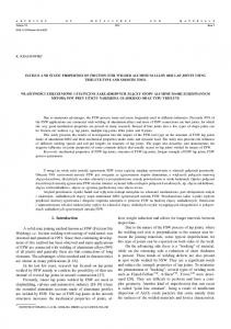
1. Introduction Friction stir welding is a solid state joining process invented in TWI in Cambridge, England in 1991 firstly for joining aluminium alloys[1]. It has made low cost welded joints due to low power consumption, absence of gas shielding, no need of joint edge preparations before welding application and low distortion because of lower welding temperature and specially high joint strength compared with conventional welding methods, i.e. TIG or laser welding, that had been widely used for this purpose before, obviously because of decreasing in metallurgical defects. It is able to join all of the aluminum alloys from 2XXX to 7XXX series that had been considered as not weld able alloys by conventional welding methods due to excessive joint strength decrease in compared with the base material. FSW can produce many kinds of joints, i.e. butt joints, lap joints and T joints. Lap joints are widely used in assemblies of parts in air craft and automotive industries. In the last years, FSW has been one of the most interests for aluminum alloys lap joints. In aircraft and automotive structures friction stir welded lap joints have been widely used with the aim to replace riveted lap joints. Rivet holes are often potential sites for crack initiation or corrosion problems; moreover, the elimination of * Corresponding author:
[email protected] (M. Tour) Published online at http://journal.sapub.org/materials Copyright © 2011 Scientific & Academic Publishing. All Rights Reserved
fasteners leads to considerable weight and cost savings. A few examples of FSW joints applied in automotive industries are some applications include engines, wheel rims and lap joints in car back supports[2-3]. In FSW process, the joint is produced by penetrating a specially designed inconsumable rotating shouldered tool pin into the interface of two pieces of sheets and moving it along the weld line to heat and stir the sheets' materials by producing friction between the shoulder and the sheet surface and also the material flow by the pin movement. As the tool moves through the weld line, the heated materials of two sheets flow and mix together without melting and make the welded joint[4]. Because in FSW the joining process is accomplished by material flow below the melting temperature, many joint defects caused by joint material melting such as porosity, grain boundary cracks and alloys segregation can be eliminated or adequately reduced. These process specialties have made FSW very practical for joining dissimilar alloys. Lately some researches have been performed on friction stir welding of dissimilar aluminum lap joints[5-7]. AA5083 is a strain hardening structural alloy that is widely used in aerospace, marine and military industries mostly because of its light weight, admissible weld ability and elite corrosion resistance[8]. Some recent researches have studied friction stir welding of this aluminum alloy in similar or dissimilar joints[9-12]. The FSW joint quality is commonly influenced by many parameters. The most effective parameters in friction stir
94
H. Bisadi et al.: The Influence of Process Parameters on Microstructure and Mechanical Properties of Friction Stir Welded Al 5083 alloy Lap joint
welded joints are the tool and process parameters such as shape and geometry of the tool, tool tilt angle and also the rotational and welding speeds of the tool during the process. Tool rotational and welding speeds are two FSW critical parameters particularly for adjusting the welding temperature. Low welding temperature may produce insufficiently stirred sheet interface and cause many defects like kissing bonds and extremely high welding temperature may lead to unexpected joint microstructure or alloys melting[13]. Also the best geometry and shape of FSW tool should be obtained to minimize welded joint defects such as top sheet thinning and hooking at the bottom sheet in lap joints. In lap joints of friction stir welding, three defects are more possible to occur: top sheet thinning, kissing bonds and hooking defects. The hooking defect can be seen mostly at the thermo-mechanical affected zone of advancing side when the sheets interface is pulled up into the top sheet. This defect causes a local thinning at the top sheet and decreases the joint strength. The kissing bond defect is resulted by insufficient heat transferred to the interface of sheets that leads to produce separated interfaces with remained oxide layers among them. This defect usually occurs at the retreating side because of its lower temperature during friction stir welding[5]. In this study, similar sheets of 5083 Al alloy were lap jointed by friction stir welding method with various tool rotational and welding speeds. Microstructure and mechanical properties such as Micro hardness and lap shear strength were also evaluated due to achieve the optimum parameters for the joint strength.
2. Experimental Procedure Sheets of Al-alloys, AA 5083, 2.5 mm thick, 150 mm long and 100 mm wide were selected for lap joint welding. A vertical semiautomatic milling machine was used for this process. The tool used for this process was made of H13 quenched and tempered steel tool with a shoulder of 20mm diameter with a inverse conical pin, 4.8mm major diameter and 3.8mm long (e.g. Fig. 1a) and was tilted by 4 ͦ to provide compressive force to the stirred weld zone. Several tests were performed by varying process parameters, namely tool rotational and welding speed. All the welding conditions are resumed in Table 1. A standard metallographic procedure was performed for macro and micro structural analysis. The samples were etched by a modified Keller’s reagent to reveal the aluminum alloy microstructure. An optical microscope was used with the aim to observe the microstructure of the weld area. For testing the lap joints shear strength, shear tensile tests were taken by putting the specimens under tensile load perpendicular to the welding direction. The tensile shear test specimens were taken by cross sectional cutting the weld zone, 18mm wide and 130mm long (e.g.Fig.2). Three specimens were taken from each welding parameter. It was reported that if the RS area of the weld is located at the edge of the top sheet, better properties will be observed for the
joint[14]. Micro hardness distribution test was taken at the depth of 0.5 mm from the bottom sheet upper surface by applying a load of 100gr for 10 seconds from a standard Vickers hardness testing probe to a cross section of welded area perpendicular to the welding direction.
Figure 1. (a) FSW tool and (b) Experimental setup for FSW process Table 1. Different experimental welding conditions Samples 1 2 3 4 5 6 7 8
Rotational speed (rev/min) 600 600 825 825 1115 1115 1550 1550
Welding speed (mm/min) 32 60 32 60 32 60 32 60
Figure 2. An example of tensile shear test specimens
3. Results and Discussions Two sheets of aluminum 5083 alloy were lap jointed by friction stir welding method. Different parameters of rotational speeds of the tool and welding speeds were applied with the aim to obtain the optimum properties of the welded lap joint. A few results were obtained on the basis of the experiments. Increasing the rotational speed with a constant welding speed leads to a larger welding area and also de-
American Journal of Materials Science 2011; 1(2): 93-97
creases the quality of the weld surface because of transferring larger amount of heat and more turbulent material flow at the weld surface (Fig. 3).
95
hooking defect at the advancing side of the weld area in two deferent conditions and also the failure in the tensile shear test caused by this defect.
Figure 4. The fracture areas in tensile shear test at different conditions, (a) 600rpm, 32mm/min, (b) 600rpm and 60mm/min
Figure 3. Effect of tool rotational speed on the weld surface quality
Table 2 shows the lap shear test results. The results indicate that at lower rotational speeds, lower welding speed leads to better shear strength of the joint. But at higher rotational speeds, changing of the welding speed has an inverse effect on the joint properties. Table 2. Maximum fracture load for specimens with various welding conditions Samples 1 2 3 4 5 6 7 8
Rotational speed (rev/min) 600 600 825 825 1115 1115 1550 1550
Welding speed (mm/min) 32 60 32 60 32 60 32 60
Maximum load(N) 10617 8872 14217 13647 13309 13615 7701 8225
Except the joints at rotational speed of 600rpm, all of the fractures took place at the heat affected zone of the advancing side at the top sheet. At the rotational speed of 600rpm two kinds of fractures were occurred. As it's illustrated in this Fig. 4a, because lower rotational speed causes lower heat generation and less material flow resulting lower bottom sheet material vertical movement, a lower bonded area is resulted. But because of fewer defects like hooking or increasing the grain size, a comparatively higher fracture load was achieved in this condition. But if the heat generation gets less than that by increasing the welding speed, insufficient stirred zone and the defects like kissing-bonds will be generated particularly at the weld center so that the fracture occurs at the weld center (Fig. 4b). The kissing-bonds defect can be seen in the joints welded by rotational speed of 600rpm. This defect is a cause of low heat transfer and high thermal gradient at the weld zone during the process. Figure. 5 shows an example of kissing bonds defect at this condition. The hooking defect is one of the most probable defects in friction stir welded lap joints. Because of higher temperature of the advancing side, hooking defect is often more obvious in this area. The more heat transfers to the weld area the larger amount of hooking defect occurs due to more turbulent material flow at the weld area. Figure. 6 shows the
Figure 5. Kissing-bonds defect in the macrostructure of the weld at 600rpm, 32mm/min
Figure 6. The hooking defect at (a) 825 rpm, 32mm/min, (b) 1550 rpm, 32mm/min and (c) The failure area by tensile shear test for specimen b
Figure 7. Optical macro images of the weld zone at: (a) 600rpm, 32mm/min, (b) 600rpm, 60mm/min, (c) 825 rpm, 32mm/min, (d) 825rpm, 60mm/min, (e) 1115rpm, 32mm/min, (f) 1115rpm, 60mm/min, (g) 1550rpm, 32mm/min, (h) 1550rpm, 60mm/min
Fig. 7 shows the optical macrostructures of the weld zone with various rotational and welding speed conditions. As it's shown, the area of the weld nugget increases with increasing tool rotational speed, while the welding speed does not clearly affect the area of the weld zone. As it’s shown, the area of the weld zone is significantly dependent on the heat generation during FSW. The higher tool rotational speed and lower welding speed have been known for generation of
96
H. Bisadi et al.: The Influence of Process Parameters on Microstructure and Mechanical Properties of Friction Stir Welded Al 5083 alloy Lap joint
higher heat input[6]. Fig. 8 shows the optical microstructures of the weld zone at tool rotational speed of 825 rpm and welding speed of 32mm/min. the heat affected zone (a,h) had the highest grain size in contrast with the stir zone(c,d) in which the finest grain size could be seen. Extended grains of the thermo-mechanical affected zone (b,f,g) can bee seen at both advancing and retreating sides of the weld area. Also in this Figure, the boundaries among stir zone, thermo-mechanical affected zone and the heat affected zone (e) can be clearly observed. Fig. 9 shows the results of the micro hardness distribution test at the weld area. For the sample shown in Fig. 9, hardness varied between 63.3 and 73HV. The minimum hardness was found in the heat affected zone of both the advancing and retreating side. Grain growth is the most proper cause of this. The hardness of the nugget was higher than other weld areas. This may be cause of the formation of very fine recrystallized grains in the nugget zone.
methods were carried out. A few results are listed below: 1-At lower rotational speeds, lower welding speed leads to better properties of the weld joint. But at higher rotational speeds, changing of the welding speed has an inverse effect on the joint properties. At lower rotational speeds because of lower material flow, lower welding speed is needed to decrease the welded joint defects by increasing the heat generation and decreasing the heat gradient at the joint areas during the process. Also at higher rotational speeds because of large amount of material flow that can cause several defects on the joint, higher welding speeds should be applied to increase the thermal gradient at the weld zone. In fact at the tool rotational speed of 600rpm the main reasons for the joint defects are caused by low heat transfer during the process and insufficient stirred joint area. Also at the higher rotational speeds like 1550rpm, excessive heat transferred to the weld area causes many defects like hooking at the thermomechanical zone of the advancing side. 2-The nugget of the weld has the finest grain size and highest hardness among the other welding areas and the base material at the tool rotational speed of 825rpm and welding speed of 32mm/min, in contrast with the heat affected zone that has the highest grain size and lower strength. In fact almost all of the fractures took place at the heat affected zone of the advancing side of the weld.
REFERENCES
Figure 8. Microstructures of the weld zone at the conditions of 825 rpm, 32mm/min
Figure 9. The results of the micro hardness distribution test taken at the depth of 0.5 mm from the bottom sheet upper surface at the condition of 825rpm and 32mm/min
4. Conclusions The friction stir welding process was used to make a lap joint of 5083 aluminum alloy. For optimizing the joint properties, different parameters including different rotational and welding speeds experimented and different testing
[1]
W.M. Thomas, E.D. Nicholas, J.C. Needam, M.G.Murch, P. Templesmith, C.J. Dawes. GB Patent
[2]
D. Fersini, A. Pirondi, Fatigue behaviour of Al2024-T3 friction stir welded lap joints, Engineering Fracture Mechanics 74 (2007) 468–480
[3]
Mats Ericsson, Lai-Zhe Jin, Rolf SandstrÖm, Fatigue properties of friction stir overlap welds, International Journal of Fatigue 29 (2007) 57–68
[4]
S, Li Y, Murr LE, Brown D, McClure JC (1999) Low temperature friction-stir welding of 2024 aluminium, Scr Mater 41.(8):809–815
[5]
L. Dubourg, A. Merati, M. Jahazi, Process optimisation and mechanical properties of friction stir lap welds of 7075-T6 stringers on 2024-T3 skin, Materials and Design 31 (2010) 3324–3330
[6]
Chang-Yong Lee, Won-Bae Lee, Jong-Woong Kim, Don-Hyun Choi, Yun-Mo Yeon, Seung-Boo Jung, Lap joint properties of FSWed dissimilar formed 5052 Al and 6061 Al alloys with different thickness, J Mater Sci (2008) 43:3296–3304
[7]
Vijay Soundararajan, Eswar Yarrapareddy, and Radovan Kovacevic, Investigation of the Friction Stir Lap Welding of Aluminum Alloys AA 5182 and AA 6022, JMEPEG (2007) 16:477–484
[8]
M. Grujicic, G. Arakere, B. Pandurangan, A. Hariharan, C.-F. Yen, B.A. Cheeseman, and C.Fountzoulas, Statistical Analy-
American Journal of Materials Science 2011; 1(2): 93-97
sis of High-Cycle Fatigue Behavior of Friction Stir Welded AA5083-H321, JMEPEG (2011) 20:855–864 [9]
CAIZHI ZHOU, XINQI YANG, GUOHONG LUAN, Effect of kissing bond on fatigue behavior of friction stir welds on Al 5083 alloy, J MATER SCI 41 (2006) 2771–2777
[10] Min-Su HAN, Seung-Jun LEE, Jae-Cheul PARK, Seok-Cheol KO, Yong-Bin WOO, Seong-Jong KIM, Optimum condition by mechanical characteristic evaluation in friction stir welding for 5083-O Al alloy, Trans. Nonferrous Met. Soc. China 19(2009) s17-s22 [11] J.J.S. Dilip, M.Koilraj, V.Sundareswaran, G.D. Janaki Ram and S.R. Koteswara Rao, Microstructural characterization of dissimilar friction stir welds between AA2219 and AA5083, Transactions of The Indian Institute of Metals, Vol. 63, Issue 4, August 2010, pp. 757- 764
97
[12] M. Movahedi, A.H. Kokabi, S.M. Seyed Reihani and H. Najafi, Mechanical and Microstructural Characterization of Al-5083/St-12 lap joints made by friction stir welding, Procedia Engineering 10 (2011) 3297-3303 [13] M. Grujicic, G. Arakere, C.-F. Yen, and B.A. Cheeseman, Computational Investigation of Hardness Evolution During Friction-Stir Welding of AA5083 and AA2139 Aluminum Alloys, JMEPEG (2011) 20:1097–1108 [14] G. Buffa, G. Campanile, L. Fratini, A. Prisco, Friction stir welding of lap joints: Influence of process parameters on the metallurgical and mechanical properties, Materials Science and Engineering A 519 (2009) 19–26