Nahrain University, College of Engineering Journal (NUCEJ) Vol.15 No.2, 2012 pp.187 - 196
The Optimization Conditions of Friction Stir Welding (FSW) for Different Rotational and Weld speeds Dr.Ayad M. Takhakh Asmaa M. Abdullah
[email protected] [email protected] Nahrain University Baghdad -Iraq
Introduction
Abstract The effect of welding parameters on mechanical properties of aluminum alloy 3003 H14 Friction stir-welded (FSW) joints were investigated in the present study. Different welded specimens were produced by employing variable rotating speeds (1000, 1250, 1500, 2000 r.p.m.), and welding speeds (20, 40, 60, 80 mm/min). Microhardness measurements and tensile strength of the produced joints were tested. The experimental results indicated that the process parameters have a significant effect on mechanical properties of joints. The optimum results of the weld gained at the parameter 80mm/min weld speed and 1500 rpm rotation speed where the efficiency reaches to 89% of the ultimate tensile strength of the parent metal
Keywords FSW (friction stir welding), Properties, Al 3003-H14.
Mechanical
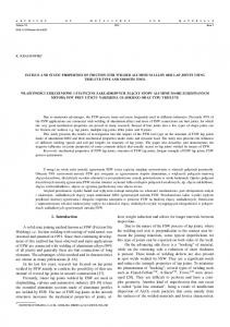
Friction stir welding (FSW) is a relatively new technique for joining aluminum alloys [1]; Friction stir welding (FSW) is a highly important and recently developed joining technology that produces a solid phase bond. It uses a rotating tool to generate frictional heat that causes material of the components to be welded to soften without reaching the melting point and allows the tool to move along the weld line. Plasticized material is transferred from the leading edge to trailing edge of the tool probe, leaving a solid phase bond between the two parts [2]. The process is carried out by plunging a rotating FSW tool into the interface of two rigidly clamped sheets, until the shoulder touches the surface of the material being welded, and traversed along the weld line. The frictional heat and deformation heat are utilized for the bonding under the applied normal force[3]. Mechanism of friction stirs welding with nomenclature shown in Fig.1.[4]
Figure 1: FSW mechanism [4]
NUCEJ Vol.15 No.2
Takhakh , Abdullah
187
Experimental work
Friction stir welding structures and properties, the influence of axial load, and the effect of position of the interface with respect to the tool axis on tensile strength of the friction stir welded joint have been studied [5-7]. Welding parameters and stirrer geometry effect, and tool effect on FSW have been studied [8-9]. The typical welding defects and welding material aspects and the Effect of Friction Stir Welding on Dynamic Properties of some aluminum alloys also have been investigated [10-12]. Other investigations have been studied the fatigue of friction stir welding and studied their properties, and crack propagation of fatigue on friction stir welding [13-19]. In this investigation mechanical properties of 3003-H14 aluminum alloy was studied after determined the best values of rotational speed and welding speed to produce best welding efficiency
In this study Al 3003-H14 was selected. The standard mechanical properties and chemical composition of Al 3003-H14 is given in table 1 and table 2 respectively. To carry out FSW process two aluminum plates 3mm in thickness, 100 mm length, and 150 mm width Fig 2, a clamping fixture was utilized in order to fix the specimens to be welded on a Hermen milling machine Fig.3. Specially prepared stirrer Fig. 4 was pressed against the bonding line and the welding process was started. The length of the stirrer was same as the required welding depth. The welding process was carried out by rotating the stirrer at different rotational and welding speeds under a constant friction force .
Table 1: Mechanical properties of Al 3003-H14 Ultimate
Yield
Shear ultimate
Fatigue
Modulus of
strength(MPa)
strength(MPa)
strength(MPa)
endurance
elasticity(GPa)
limits(MPa) 150
145
95
69
60
Table 2: Chemical Composition of Al-3003 H14 alloy
Measured
Zn
Cu
Fe
Pb
Mn
Ti
Si
Mg
Co
Al
0.046
0.104
0.402
0.002
1.041
0.122
0.192
0.0
0.015
Balance
Standard
0.12
1.2
0.18
Balance
Figure 2: Al 3003-H14 plates dimensions
NUCEJ Vol.15 No.2
Optimization Conditions of Friction Stir
188
Nahrain University, College of Engineering Journal (NUCEJ) Vol.15 No.2, 2012 pp.187 - 196
Figure 3: Hermen milling machine, clamps and fixtures
5.5
7
22
Figure 4: FSW tool
Understanding the tool design plays a very important role in friction stir welding products. The initial FSW tool designed was a simple cylindrical tool with 22 mm shoulder diameter and 7mm pin diameter, height of the pin equal to the distance that plunged in the plate and it was 2.9 mm of the sheets processed. The forces generated using this tool especially during the penetration of the tool into the work piece, were
NUCEJ Vol.15 No.2
very high and caused excessive machine vibration. Then the pin of the tool is tapered (Fig. 4) in order to reduce the initial high forces during plunging operation, the welding tool was made of tool steel X38 as the chemical composition shown in table 3.
Takhakh , Abdullah
189
Table 3: Chemical Composition of welding too C
Si
o.88-o.96
o.45
Mn 0.40
P 0.03
Cr 0.03
Given the Al-Mn alloys are rather easily weldable even with conventional techniques; it was decided to verify weldability of AA 3003 H14 alloy by the most possible range of process parameters of friction stir welding. Different welded specimens were produced by employing variable rotating speeds (1000, 1250, 1500, 2000 r.p.m.), and welding speeds (20, 40, 60, 80 mm/min).
FSW results The friction stir welding joints were shown in Fig. 5. Visual inspection shows different results of welding shapes where some welds shows
2000 rpm,20 mm/min
2000rpm,40 mm/min
Ni -
Mo 4.7-2.0
Co 4.5-5.0
Fe Balance.
presence of flash as shown in Fig.6. Because of the plunging depth of the tool this can be avoided by controlling it which must be little more than the plate thickness .Tunnel defect was found at the intersection of weld nugget and thermomechanically affected zone due to high rotational speed and travel speed. By optimizing rotational speed 1500 rpm and travel speed 80 mm ∕ min this defects was avoided. Others show presence of pin hole this easily removed using filler and getting finer shape, Fig.6 presented the visual inspection of welding results. [20-21]
1250 rpm,40 mm/min
1500 rpm, 40 mm/min
2000rpm,80 mm/min
1000 rpm ,20 mm/min
2000 rpm, 60 mm/min 1250 rpm ,20 mm/min
NUCEJ Vol.15 No.2
Optimization Conditions of Friction Stir
190
Nahrain University, College of Engineering Journal (NUCEJ) Vol.15 No.2, 2012 pp.187 - 196
1500 rpm, 20 mm/min
1000 rpm,60 mm/min
1250 rpm ,60 mm/min
1000 rpm, 40 mm/min
1500 rpm ,60 mm/min
1000 rpm, 80 mm/min
1250
rpm,
80
mm/min
1500 rpm, 80 mm/min
Figure 5 :The appearance of upper surface of welding beads of Al 3003-H14
plates produced
with Friction Stir Welding.
NUCEJ Vol.15 No.2
Takhakh , Abdullah
191
Figure 6: flash and voids formation
Fire 7: Visual inspection of FSW joints
“ All dimensions in millimeter “ Figure 8: Tensile Test Specimen
A simple tensile test was carried away using a tensile testing device, the strain was read using a dial gauge to read the strain in load direction, the test specimens of 3003-H14 aluminum alloy were prepared according to the ASTM D638M-
NUCEJ Vol.15 No.2
89 standard specimen the geometry is shown in Fig.8
Optimization Conditions of Friction Stir
192
Nahrain University, College of Engineering Journal (NUCEJ) Vol.15 No.2, 2012 pp.187 - 196
Figure 9: Tensile test results
Welding processes were carried out with four different Weld speeds and four different rotational speeds as shown in table 4. Tensile and hardness tests for FS welds done at room temperature, tensile results shown in Fig 9. The best result obtained at 1500 rpm and 80 mm/min and the efficiency 89 % of the base metal Al 3003 H14. Micro hardness test were prepared in order to characterize the hardness profile in the vicinity of
the weld affected area i.e. NZ, TMAZ, and HAZ in the FSW specimens. Also the hardness profiles are extremely useful, as they can assist in the interpretation of the weld microstructure and mechanical properties. Each specimen was tested by dividing it into regions each point tacked 30 second with hardness Vickers (HV) then the reading has been recorded and measuring the other point respectively. The results are presented in Fig. 10
.
NUCEJ Vol.15 No.2
Takhakh , Abdullah
193
(a)
(b)
(c)
(d)
Figure 10 : Hardness profiles of the FSW with deferent parameters: (a) 1000, (b) 1250, (c) 1500, (d) 2000 rpm rotational speed
NUCEJ Vol.15 No.2
Optimization Conditions of Friction Stir
194
Nahrain University, College of Engineering Journal (NUCEJ) Vol.15 No.2, 2012 pp.187 - 196 From Fig. 10 noted that results shows increasing in hardness from center to the parent metal and the lowest value is observed in the nugget zone because that Al 3003 is a strain hardened
tempers of the non-heat treatable alloys Fig. 11
[22],
.
Figure 11: hardness distribution of strain hardened tempers of the non-heat treatable alloys [22]
The hardness results shown that, in the strain hardened tempers of the non-heat treatable alloys, the recrystallization occurs in the nugget zone during FSW, would eliminate some or all of the cold work effects. This, in turn, would lead to nugget softening and the development of as welded hardness distributions are similar to that depicted in Fig. 11 which shows the hardness distribution of strain hardened tempers of the non-heat treatable alloys [22]. It should be noted that a local material softening occurs in the weld because of the thermal action of the welding process; in particular a localized softening in the NZ is observed. Note that results will show increasing in HV from center to the parent metal and the lowest value is observed in the nugget zone. The joint strength was investigated with tensile tests, to give an average value of the ultimate tensile strength equal to the 89% of the UTS of the parent material, again fractures in many samples were occurred nearby the HAZ, in correspondence to the lowest values of microhardness the micro-hardness was obtained along the transverse joint section, indicating a strong improvement of the joint mechanical characteristics [23], but other samples occurs in the nugget zone at the center of the weld
. Conclusions The influence of FSW parameters on the tensile and microhardness properties of FS-welded 3003 H14 Al alloy at various FSW conditions was examined in the present study. 1. Tunnel defect was found at the intersection of weld nugget and thermo-
NUCEJ Vol.15 No.2
2.
mechanically affected zone due to high rotational speed and travel speed. The design of tool with tapered pin was suitable to avoid tool breakage
3.
Mechanical properties of FS welded aluminum alloy 3003 H14 are influenced by process parameters. Hardness drop was observed in the weld region. The softening was mostly evident in the nugget zone because that Al 3003 is a strain hardened tempers of the non-heat treatable alloys. The optimum efficiency for joints of the using parameters of FSW founded at 80 mm/min weld speed and 1500 rpm rotation speed it reaches to efficiency 89% of the ultimate tensile stress of the base metal. Acknowledgments The author is grateful to laboratories in Al-Nahrain University, and special thanks to Nassr State Company for mechanical industries and all workers in it .
References
[1] Y. J. Chao, et. al, ''Effect of Friction Stir Welding on Dynamic Properties of AA2024-T3 and AA7075-T7351", Welding Research Supplement, pp.196-200, 2001. [2] D. Lohwasser, "Friction stir welding: From basics to applications'', 2010. [3] K. Kumar and Satish V. Kailas, ''The role of friction stir welding tool on material flow and weld formation'', Materials Science and Engineering A, vol. 485, pp.367-374, 2007.
Takhakh , Abdullah
195
[4] R. Nandan et. al.,” Recent advances in friction-stir welding – Process, weldment structure and properties”, Progress in Material Science, vol. 53, pp.980-1023, 2008. [5] Mats Ericsson, "Influence of Welding Speed on the Fatigue of Friction Stir Welds, and Comparison with MIG and TIG", 2001. [6] R. S. Mishraa and Z.Y. Mab, ” Friction stir welding and processing”, Materials Science and Engineering R, vol. 50, pp.1-78, 2005. [7] K. Kumar and Satish V. Kailas , ” On the role of axial load and the effect of interface position on the tensile strength of a friction stir welded aluminum alloy”, Material and Design, vol.29, pp.791-797, 2008. [8] P. Cavaliere et. al., ” Effect of welding parameters on mechanical and microstructural properties of dissimilar AA6082–AA2024 joints produced by friction stir welding”, Material and Design, vol.25, pp.1-8, 2008. [9] Mustafa Boz and Adem Kurt, “The influence of stirrer geometry on bonding and mechanical properties in friction stir welding process”, Material and Design, vol.25, pp.343-347, 2004. [10] Hua-Bin et. al., ”The investigation of typical welding defects for 5456 aluminum alloy friction stir welds”, Materials Science and Engineering A, pp.61-69, 2006. [11] Bogdan Radu et. al., “Aspects of the Material Flow during Friction Stir Welding of 5754 Al Alloy” , Institute for welding and Material Testing, Romania, pp.1-10, 2007. [12] Tomotake Hirato, et. al., “ Influence of friction stir welding parameters on grain size and formability in 5083 aluminum alloy”, Materials Science and Engineering A, vol.456, pp.344-349, 2007. [13] Eui I. Lim, ” Fatigue Crack Propagation and Stable Tearing in
NUCEJ Vol.15 No.2
Friction-Stir-Welded Aluminum Sheet”, pp.1-29, 2006. [14] H. J. K. Lemmen et. al., ” Detailed strain field analyses of fatigue cracks in friction stir welded joints”, Aerospace structures and materials, pp.1-23, 2009. [15] Dwight Burford et. al., “Advances in Friction Stir Welding for aerospace applications”, Airframer, ISSUE 14, PP.3-7, 2006. [16] B. B. Verma et. al., “Study of fatigue behaviour of 7475 aluminium alloy” , Bull. Mater. Sci., vol.24, No.2, pp.231-236, 2001. [17] Omar Hatamleh et. al., “Fatigue Crack Growth of Peened Friction Stir-Welded 7075 Aluminum Alloy under Different Load Ratios” , Journal of materials Engineering and performance, 2009. [18] D. Booth snd I. Sinclair , “Fatigue of Friction Stir Welded Aluminium Alloy 2024T351” , Material Research Group, University of Southampton, pp39-40,2000. [19] Jeff Horschel , “Fatigue of Friction Stir Processed 2024-T3 Aluminum for Aerospace Applications”, 2005 [20] J. Adamowski, et. al., ’’ Analysis of FSW welds made of aluminium alloy AW6082-T6’’, Materials Science and Engineering, vol.28,pp.453-460, 2007. [21] G. Raghu Babuet. al., ” An experimental study on the effect of welding parameters on mechanical and microstructural properties of AA 6082-T6 friction stir welding butt joints”, Journal of Engineering, vol.28, pp.68-74, 2008. [22] Terry Khaled, "An outsider looks at friction stir welding", ANM-112N-05-05, PP.1-71, 2005. [23] A. Barcellona et. al., “On microstructural phenomena occurring in friction stir welding of aluminium alloys”, Journal of Materials Processing Technology, Vol.177, pp.34-343, 2006.
Optimization Conditions of Friction Stir
196