From Circuit Simulation to Circuit Verification: An Internal + Boundary Scan-based Solution Gustavo R. Alves DEE / ISEP Rua S. Tome 4200 Porto – Portugal
[email protected]
Marcelo S. Lubaszewski Margrit Reni Krug PPGC / UFRGS Av. Bento Gonçalves, 9500 CEP 91501-970 Porto Alegre – Brasil
[email protected] [email protected]
Abstract Matching the results obtained from circuit simulation with those extracted from circuit functioning is a common stage of the final verification process. Many current verification techniques use the I/O vectors produced during functional and / or timing simulation, for creating the test vectors to be applied / compared against the circuit responses. Techniques that are more complete include extracting the values of internal sequential nodes and comparing these using internal scans. This paper describes such a solution for verifying digital designs implemented in currently commercial available CPLDs. The test program is automatically generated from information that encompasses the design & development phase, namely: the file containing the results from simulation, the BSDL file, an internal scan chain description file, and one file containing the user options.
1. Introduction Comparing the results obtained from the simulation phase with those extracted from real circuit behaviour is a traditional method of circuit verification, sometimes referred as functional test. While this method can be extended to comparing the values of internal flip-flops (FFs), the need for expensive test equipment prevents such an approach for small research groups with limited budgets [1]. The presence of a Boundary Scan Test (BST) infrastructure in current commercial available Complex Programmable Logic Devices (CPLDs) is a possible solution for implementing a similar approach using two optional instructions described in the standard [2] and a chip-level controller for debugging & testing board-level applications [3, 4]. The INTEST instruction allows the application of a test vector to input pins and the capture of a response vectors in output pins, while a user-defined optional instruction called ‘INTSCAN’ allows capturing the values present in internal sequential nodes. The test controller named PROcessor for DEbug Purposes (PRODEP) is responsible for controlling all test operations. The test program executed by PRODEP is automatically generated from information that encompasses the design & development phase. Key points of our solution include: a low-cost approach dispensing the use of complex test equipment, re-use of simulation results, a board-level BS controller, and use of simple in-
José M. Martins Ferreira DEEC / FEUP Rua dos Bragas 4000 Porto – Portugal
[email protected]
house software (the automatic test program generation ATPG - tool). Other contributions include: identification of flaws in INTEST and in the BSDL file, in what refers to access through the TAP to internal scan chains. This paper is organised as follows: section 2 describes the test program generation process, namely the data flow and the I/O information. Most of this process is actually devoted to ordering information extracted from existing files. The considerations on INTEST and on the BSDL file are included in this section. Section 3 describes how the test program is executed, section 4 is devoted to the error detection / location / diagnosis process, and section 5 concludes.
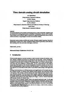
2. The test program generation data flow The data flow in the test program generation process is illustrated in fig. 1. Most of the input information required by the ATPG tool is provided from earlier stages of the design & development process. The tool requires: the simulation results; the BSDL file; a file describing the internal scan chain ordering; a file containing the user options; and the structural test vectors (optional).
Fig. 1: Data flow of the ATPG process The first file contains a complete description of all the simulation channels used, i.e. the pins and the internal FFs. Interpreting this file is sometimes a major problem, as there isn’t a widely used public or de facto standard for its format. The one generated by the MaxPlusII development
system [5] comes in a tabular form, in ASCII, where columns correspond to circuit signals and rows correspond to time moments. The cell corresponding to a row (time) – column (signal) intersection contains the signal value of a particular circuit location in a particular moment. Simulation files in this format (with minor variations) are quite common, and in fact, they represent a kind of files that are easier to process. In our case, we developed a simple C program that performs this operation, providing the information needed to the ATPG tool. The BSDL file maps the device pins to the corresponding BS cells. Our approach includes two options: the vectors may either be applied / captured through the BS cells of device, using INTEST, or through the BS cells of other devices, using EXTEST. The second option requires additional components to provide the BS cells used as test channels, while the first option has other drawbacks. The BSDL file also contains the opcodes of all instructions. Currently there is a serious omission in this file, namely the standard does not define a way of presenting the ordering of an internal scan chain accessible through the TAP. This information has to be provided by a different file. The user configuration file contains additional information, namely some options associated with the resources available in our board-level BS controller. The last file enables a structural test of the circuit implemented in the CPLD. The ATPG tool processes the input information and produces two output files corresponding to the programs executed by each of the two controllers embedded in PRODEP. One controller (CLT) is able to control two BS chains and the other (CLF) is able to control one system clock and several general-purpose I/O pins.
3. The test program execution The two controllers embedded in PRODEP interpret the two files forming the test program. The internal structure of PRODEP is described in [4], so we will concentrate on the test program execution. The basic procedure consists of apply one input vector used during simulation; cause the device to advance one step in its operation; capture / shift / compare the values present at the output pins and internal FFs. The first action consists of moving the TAP controller to Shift-DR, shift in the test vector and then moving to Update-DR. This action is similar if using INTEST plus the device BS cells, or EXTEST plus the BS cells of other devices. The second action may be performed in several ways, according to the information provided in the user options file. This information is closely related to the examples provided in [2], on how a step-by-step operation may be implemented for internal test operations. As one of the controllers embedded in PRODEP is able to control one system clock, the user is able to choose between an external or internal clock source (this last controlled through the BST infrastructure). The last action includes two parts. The first corresponds to moving the TAP controller to Capture-DR (where the response to the test vector is captured), moving further to Shift-DR, and then shift out the captured vector. The second part corresponds to loading the optional
‘INTSCAN’ instruction and then performing a circular shift, i.e. the values shifted out of the internal scan chain are also shifted in, so that the scan chain contents remain the same. Meanwhile, the shifted values are also compared (through a mask) against the expected ones, inside PRODEP. This way, PRODEP is responsible for the error detection phase.
4. The detection / location / diagnosis process A mismatch between a captured / expected value causes PRODEP to acknowledge error in an output pin. The test program may then be halted through conditional instructions that test the internal error flag, or continued up to the end. Error location is performed by an in-house tool that extracts the vectors captured by PRODEP (values shifted into PRODEP are stored in an external memory) and compares the last with the corresponding expected one. The next step consists of identifying the offending bit, i.e. which value differs in the captured vector, in relation to the expected one. After the bit order is identified, the tool combines the information provided by the internal data structure to locate the offending node. Diagnosis implies an additional simulation session. By looking into the time slot where the error is detected, namely to the value of the offending node, the user is able to identify possible error sources. If more information is needed the user may run a more specific simulation session with corner cases surrounding the exact error situation, and then generate another test program. The new values extracted from the circuit behaviour may then help to find a solution to the actual error. This last process can be repeated several times until the user is certain that the exact error condition has been unequivocally identified and that the envisaged solution is correct.
5. Conclusion This paper describes a low-cost methodology for performing circuit verification. Key points are re-usability of files that encompass the design & development phase, re-usability of the BST infrastructure for debug purposes (besides the traditional production test), and use of easy-todevelop in-house applications.
6. References [1] K. Holdbrook et. al., “microSPARCTM: A Case-Study of Scan Based Debug,” in proceedings of the International Test Conference, pp. 70-75, IEEE Computer Society Press, 1994. [2] IEEE Standard Test Access Port and Boundary-Scan Architecture, Oct. 1993, IEEE Std. 1149.1 (Includes IEEE Std. 1149.1a), ISBN 1-55937-350-4. [3] Gustavo R. Alves, T. Amaral and J. M. Ferreira, “Board-level Prototype Validation: A Built-in Controller and Extended BST Architecture,” in proceedings of the International Symposium on Circuits and Systems (ISCAS), IEEE Circuits and Systems Society Press, 1999. [4] G. Alves, “Design for Debug and Test based on the 1149.1 and P1149.4 architectures”, PhD Thesis, FEUP, Apr. 1999. [5] Altera Corporation Web site, http://www.altera.com, 1999.