From Scene Graph Centered to Entity Centered Virtual Environments Florian Mannuß∗
Andre´ Hinkenjann†
Jens Maiero‡
University of Applied Sciences Bonn-Rhein-Sieg
A BSTRACT Todays Virtual Environment frameworks use scene graphs to represent virtual worlds. We believe that this is a proper technical approach, but a VE framework should try to model its application area as accurate as possible. Therefore a scene graph is not the best way to represent a virtual world. In this paper we present an easily extensible model to describe entities in the virtual world. Further on we show how this model drives the design of our VE framework and how it is integrated. Index Terms: D.2.11 [Softwar Engineering]: Software Architectures—Domain-specific architectures I.3.7 [Computer Graphics]: Three-Dimensional Graphics and Realism—Virtual reality 1 I NTRODUCTION When developing a Virtual Environment Application using a VE framework, the virtual world is mostly centered around a scene graph. As a consequence, things (objects) that are an entity in the virtual world are collections of nodes in this scene graph and are accessed as those. If we want to interact with a ball in our world, a possible call can look like ”Transform Node of Ball”-> setMatrix( value ). Here, the developer needs to keep two different views in mind: the virtual world view with the objects as one entity and also the developers view of the scene graph. This dichotomy is a repeating pattern throughout the whole scene graph centered application development process. Field mechanisms are often used to connect objects together. In a scene graph based world these connections again connect scene graph nodes instead of whole objects. The same holds for input devices. From a developers view the user does not interact with an object, instead she/he interacts with a transformation node connected to the input device through a field mechanism. We think that this is a solution to solve the technical requirements, but we think that this approach is not very intuitive and does not use the real world as a prototype. A framework whose aim is to provide an abstract model of its application domain, that is a virtual world based on the real world, should model this domain as accurate as possible. An abstract model that describes those virtual objects as an entity and which is yet easily extensible is presented in this article. In the following section an overview of some VE-Frameworks and their object model is given. After that, we examine how to describe objects of the real world and in section 4 we use this results to derive the design of the framework. Some example applications are described in section 5 and we finish with a r´esum´e and some future work. ∗ e-mail:
[email protected] [email protected] ‡ e-mail:
[email protected] † e-mail:
2
R ELATED W ORK
Modern VE-Frameworks like Avango [7], Lightning [1], VR Juggler [2] and Maverik [5] are all centered around some sort of scene graph. This results in the objects of the virtual world being a loose collection of nodes in a scene graph. Avango is directly tied to the Performer scene graph which it encapsulates. Adding new components is done by writing new nodes. Using a field mechanism, nodes can be connected with each other. With VR Juggler the user can choose between different scene graphs or OpenGL and has to issue the corresponding API calls. No field mechanism is provided. Lightning provides an object pool and interfaces to certain nodes, like transformation and material. These interface must be implemented by the programmer, enabling the possibility to exchange the scene graph. However, if new objects are needed the interface must be added to the base system and objects are still “graph nodes”. Maverik provides a spatial data structure to store data. Objects are again low level primitives, like geometric objects. They are not part of the micro kernel and have to be registered in order to be usable. With the built-in spatial data structure fast collision or ray intersect queries are possible without the need to duplicate data as in a scene graph based world. A very radical approach is chosen in [3] because the task was restricted to urban planning processes. Here, all objects are modeled as single classes. This is acceptable for such a restricted application domain, but for a generic system it is no viable solution. Closest to our approach is the dVs system [4]. dVs describes its virtual world with objects that aggregate attributes, too. However, the set of attributes is predefined and adding new complex attributes results in extending the whole system. A new and interesting approach is used in Hector [8]. Here, all system components are glued together using Python. In practice, this approach is restricted to the application logic only, due to the heavy overhead of data exchange between Python and C++. Again, the system is centered around a scene graph and wrapper classes to these nodes are implemented in Python. A common characteristic of all described systems is the coupling of data and rendering. 3
D EFINING
THE
V IRTUAL W ORLD
How can we describe the objects of the real world in a generic way? The task is to describe the objects as a composition of their basic characteristics. Such a description can be made in form of a list, e.g. “red, round, 10 cm diameter, 100 gr. of weight, soft, ...”. These are all perceivable impressions. Through variation the essence of an object can be abstracted. With variation we don’t describe a single ball, instead we extract the essence of all balls and in the description the red color of the ball group simply becomes color. Other characteristics stay constant, like the round shape. For our task this abstraction level is not enough, since we don’t want to have a separate description for every object group, like ball, book or door. For our framework we seek a solution with which we can model every group of object, even abstract data sets. The consequence is to abstract the object group. Resulting in the proposition that every group’s essence can be reduced to an arbitrary amount of static and dynamic base characteristics. Furthermore, the quantity of characteristics cannot be determined
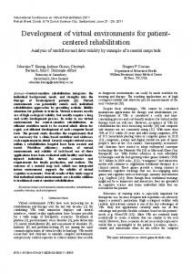
in advance. 4 D ESIGN In addition to the above mentioned requirements there are a couple of software-engineering requirements for the system design. The base system should be small, easy to extend and run-time configurable. From this demands we can derive further requirements. All extensions must not be part of the base system. They are all loaded as shared objects at run-time. The system is component based and uses the principle of locality1 . Our system should support concurrency and be extensible by scripting languages. Finally, all utilized third party libraries must be replaceable. We don’t want to be dependent on specific libraries, like scene graph-, sound- or physics-APIs. 4.1 System overview Our VE-Framework is divided into five main components as seen in figure 1. The connecting lines characterize the information
Figure 1: Kernel sketch with the plug-in interfaces. The numbered lines show the calling order of the single components during one main-loop cycle. Objects marked with (*) are called through the main loop directly.
flow within the system. The Scene component is responsible for storing and representing the virtual world. The Attendee (compare section 4.3) has a special purpose within this virtual world, since it is the representative of the actual user. The attendee is part of the virtual world and it belongs consequently to the Scene component. The Manipulator component is responsible for managing engines, which manipulate the virtual world and sense renderers for stimulation of the user (manipulation of the outputs). Figure 5 shows three example engines for manipulating the virtual world. Input Devices handles all known physical input devices and Actions manages all possibilities how the user can interact with the scene or manipulate it. Some example of actions are “create new object”, “delete object”, “move object” or “interact with object”. The way an action works depends on the action. “create new object” immediately processes the request and creates a new object. “Interact with object” will send a “interact message” to the virtual object and the virtual object will process the request itself. Sending and receiving messages is not limited to actions and virtual objects. The Scene component itself sends a change message for every virtual object that was changed. The Scripting component provides a facility for programmers to extend the 1 Locality is important for extensible systems, since it ensures that new components have no cross references to source locations. For example, when adding a new object (e.g. a sphere) to a VR modeling application, we don’t want to search the code for the place to add the menu entry “Sphere”. All should be done at one place in the code.
framework using a scripting language or to develop applications with the benefits of run-time manipulation and rapid prototyping. All components only provide the interfaces and all input devices, actions, virtual object attributes, renderers and scripting support are implemented as plug-ins that are loaded during run-time. Free Plug-Ins are all extensions that are not coupled directly with one of the main components. They automatically integrate into the system, like spatial data structures as shown in figure 5. They register themselves for all object change messages and are therefore informed about all changes. 4.2
Virtual Objects and the Virtual World
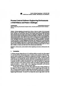
Using the characterizations from above we need to divide the characterization (attributes) of an object from its representation (perception). In technical terms the perception, realized by sense renderes has to be separated from the object description in our VE-Framework design as seen in figure 1. Manipulators and Scene are the two components responsible for this separation. How can we represent an object, although we cannot know all possible attributes in advance? A logical consequence is to provide the possibility to add any attribute we need. In our system objects are represented through a class called virtualObject in the system kernel. This class holds no attributes (like geometry or material). Attributes are aggregated as a “is part of” relation. Thereby, no attributes can be stored in the kernel. Attributes are implemented as plug-ins and are loaded to the Scene component at run time. Only the base class of all attributes is known to the kernel. Attributes can describe anything, consequently a uniform way to access them is needed. Our solution is to forbid to directly access attributes and use the virtual object as mediator. The only way to access attributes is a set/get-method pair of the virtual object. In order to specify the request, like “set the diffuse material colour to red”, a command object is needed. This command object is passed to the virtual object and from there to the appropriate attribute that processes the request. The description of an attribute is specified in a plain text file. All attributes have to register a prototype at the attribute object factory. This factory is then used to create the attributes. With this the static description of a virtual object is completed. The dynamic description, like the movement, still has to be done. Such dynamic situations appear when the user interacts with a virtual objects or virtual objects interact with each other, e.g. after collision. Such interactions are handled by the virtual object through functionality objects. As in the attribute case, only the functionality base class is known to the kernel. All functionalities are loaded through plug-ins and register themselves at the functionality object factory. They have to register themselves for all messages they want to receive. Often, functionalities are bound by constraints, so every functionality can hold one or more constraint function and only if all of them return true the request is processed. There are two ways a constraint function can be added. The first way is shown in figure 2. The constraint needed here is to ensure the correct functionality
Figure 2: Objects and functionalities needed to represent a door. The S/G boxes symbolize the set/get method pair to access the attributes shown in the top of the objects.
of a door. Its task is to ensure that the user can only open the door up to a certain position and that if the door is closed it has to be first opened with the door knob. Here, the constraint is bound to a certain type of object. In the second way, shown in figure 3, the constraint is set for all functionalities of a certain type. In the example the physics
As sketched in figure 5 the attendee is the linkage between the virtual and the real world. Consequently, an attendee knows all input devices associated with it and is responsible to create the sensual output for the user. For every input device a virtual object can be added as a representation. Further on, the attendee knows its position and viewing direction. This information is passed to its sense renderers. The attendee’s task is to query its input devices and to call the active or configured action. As the last call during the main loop cycle the attendee calls its sense renderers. Putting the input devices and the sense renderers into the attendee is a logical choice. Especially if there are different attendees in a collaborative environment, the mapping of the input devices and the sense renderers would be spread over the different system components and thus violating our principle of locality.
Figure 3: Sample of a functionality class constraint. Here the physics plug-in sets itself as a constraint for all move functionalities.
renderer, implemented as a plug-in, sets itself as constraint to all move-functionalities. If the user wants to move the ball, the physics renderer first verifies that the user is strong enough to move the ball. In this case the physics attributes have to be updated also. This is done by using a transfer function. They are added like the constraints to the functionality, but are only processed if all constraints are fulfilled. If the physics renderer is not loaded the move functionality will work correctly, just without the physics. Virtual objects can be connected as shown in figure 4. The con-
Figure 5: Illustration of the coupling of the real and virtual world. The attendee is the central connection. It is responsible for the sensual stimulation of the user and the processing of user interaction.
4.4 Figure 4: Two virtual objects with a bidirectional connection. The transfer function calculates an offset, to ensure that both chairs do not overlap. The numbers indicate the calling order.
nection can be directional or bidirectional. As in the functionality case, constraint/transfer functions can be added. Connections can connect all attributes or only selected attributes. In order to prevent cycles two options are available: the cycle can be cut of or the cycle can be cut but continued in the following frame. In order to group virtual objects to complexer entities they can be grouped in a container. The container itself is a virtual object and can store attributes. As a limitation, a virtual object can only be added to one container. A virtual world object, derived from virtual object is automatically created by the system. This object is the place to store system wide parameters, like the gravity for the physics engine and of course the geometry describing the ground of the virtual world should be stored here. The world object is also storing all virtual objects. 4.3 Attendees Attendees are derived from virtual object and represent the user.
Manipulators
Doing all scene manipulations with functionality objects is not always the best choice. Especially when using third party libraries (like a physics engine or some artificial intelligence). For these tasks an additional component, next to the sense renderers, is available, called engines. Both components are shown in figure 1 as part of the manipulator component and figure 5 shows a few examples of different engines, like a NURBS tesselator, a physics engine or some AI for system avatars. The sense renderer and engines are grouped into one component. This is because both are “manipulating”. In the sense renderers case the users senses are stimulated or manipulated and in the engines case the objects of the virtual world are manipulated. Because the sense renderers do not change the virtual world they can run concurrently. In the engines case this is not possible and this manipulator class is called sequentially. Sense renderers are the renderers needed for the sensual stimulation of the user, like graphics, sound or haptics renderers. The sense renderer is dependent of the attendees position, whereas the engines are usually independent of the attendees position. The graphics renderer needs an in between layer, due to the different display systems. In this case the display abstraction plug-in is the sense renderer that loads the graphical renderers itself.
4.5
Global Data Structures
In figure 5 a global spatial data structure plug-in is shown that is used by more than one manipulator (e.g. a ray tracer and a physics engine). In a virtual environment different spatial queries are performed by different components. The physics engine executes collision queries, the ray tracing renderer issues ray/object intersection queries and a proximity sensor needs a proximity query. All those queries use spatial acceleration structures and if such data structures are not implemented at a common place every component has to build its own structure. This is error-prone and memory consuming. The spatial data structure plug-in offers centralized data structures and can be configured with different data structures for usage. Using this plug-in structure enables us to exchange the underlying spatial data structure by simply changing the system configuration without rewriting application code. 5
E XAMPLES
One of our configurations uses Open Scene Graph encapsulated in an attribute plug-in and a graphical renderer. The input device is a 6DOF device connected through vrpn or a mouse for desktop usage. Further on, animation and physics renderer and attribute plug-ins are available. The ODE-engine is used for physics. Scripting can be done using Python or Java. Since Java is not interpreted it cannot be used for run-time modification. This configuration is used for teaching and student exercises. An action plug-in implementing the most basic actions, like “move camera”, “move object” or “interact” is also available. During the lab night at IEEE VE’05 in Bonn we showed a mixed rendering sample application using our VE-Framework. The display abstraction divided the scene to be processed by different rendering algorithms and the results were merged by depth comparison. We utilized ray tracing, point based rendering and hardware rendering. The modified display abstraction and the renderer are implemented as plug-ins and can be used in further projects. In [6] we describe the integration of flexible cables and tubes into our VE-Framework and showed a demo application at Hannover Messe 2007. In order to integrate the engine we had to write a new attribute plug-in storing the attributes of the cable, an engine to create the geometry of the cables and a plug-in with tube-specific actions, like joining, splitting, creating or deleting cables. Those three additional plug-ins seamlessly integrate into the existent system. 6
C ONCLUSION
AND
F UTURE W ORK
We described the design ideas of our VE-Framework. The object model defines our virtual world and describes objects as an entity. An object has a static part, called attributes and a dynamic part, called functionalities. Both parts are arbitrarily extensible either through new plug-ins or directly by an application. In addition, we separated the object description from its presentation (rendering). This has the effect that the renderer can easily be replaced. Future work includes the integration of a collaboration model that allows two or more people to interact or collaborate in the virtual world. Another enhancement is to add a SQL-like set language in order to be able to comfortably filter objects with certain properties, like all transparent and reflective objects within a specified distance to the active attendee. This is useful for dynamic renderer selection in mixed rendering environments. Another important feature yet to be implemented is persistence to be able to save the complete virtual world when quitting and to continue working at this stored location. ACKNOWLEDGEMENTS This work was partially sponsored by the German Federal Ministry of Education and Research (BMBF) under grant no 1762X07
R EFERENCES [1] R. Blach, J. Landauer, A. R¨osch, and A. Simon. A Highly Flexible Virtual Reality System. In Future Generation Computer Systems Special Issue on Virtual Environments, Elsevier Amsterdam, 1998. [2] C. Cruz-Neira, A. Bierbaum, P. Hartling, C. Just, and K. Meinert. VR Juggler – An Open Source Platform for Virtual Reality Applications. 40th AIAA Aerospace Sciences Meeting and Exhibit 2002, Reno, Nevada, January 2002. [3] T. Gaborit, N.; Howard. A collaborative virtual environment for public consultation in the urban planning process. Theory and Practice of Computer Graphics, 2004. Proceedings, pages 104–111, 8-10 June 2004. [4] S. Ghee. dVs - A distributed VR systems infrastructure. In A. Lastra and H. Fuchs, editors, Course Notes: Programming Virtual Worlds, pages 7–1 – 7–30. SIGGRAPH’95, 1995. [5] R. Hubbold, J. Cook, M. Keates, S. Gibson, T. Howard, A. Murta, A. West, and S. Pettifer. Gnu/Maverik: A Microkernel for Large-Scale Virtual Environments. Presence: Teleoper. Virtual Environ., 10(1):22– 34, 2001. [6] F. Mannuß, A. Hinkenjann, G. G¨obbels, and M. G¨obel. Simulation of Flexible Tubes in VR. In ISVC07 - International Symposium on Visual Computing, Reno, USA, 2007. Springer Verlag. [7] H. Tramberend. Avango: A Distributed Virtual Reality Framework. In Proceedings of AFRIGRAPH 2001, 1st International Conference on Computer Graphics, Virtual Reality and Visualization in Africa. ACM, November 2001. [8] G. Wetzstein, M. G¨ollner, S. Beck, F. Weiszig, S. Derkau, J. P. Springer, and B. Fr¨ohlich. HECTOR - scripting-based VR system design. In SIGGRAPH ’07: ACM SIGGRAPH 2007 posters, page 143, New York, NY, USA, 2007. ACM.