Dec 15, 2008 - arXiv:hep-th/0510253v2 15 Dec 2008 · hep-th/0510253. QMUL-PH-05-12 .... Consider a free scalar field (which is not necessarily massless). ..... b become collinear, the amplitude factorises as [5,29,35]. A1âloop ..... P2Q2 â st. = ...... less Yang-Mills Field, In J. R. Klauder, Magic Without Magic, San Francisco.
hep-th/0510253 QMUL-PH-05-12
From Trees to Loops and Back
arXiv:hep-th/0510253v2 15 Dec 2008
Andreas Brandhuber, Bill Spence and Gabriele Travaglini1 Department of Physics Queen Mary, University of London Mile End Road, London, E1 4NS United Kingdom
Abstract
We argue that generic one-loop scattering amplitudes in supersymmetric Yang-Mills theories can be computed equivalently with MHV diagrams or with Feynman diagrams. We first present a general proof of the covariance of one-loop non-MHV amplitudes obtained from MHV diagrams. This proof relies only on the local character in Minkowski space of MHV vertices and on an application of the Feynman Tree Theorem. We then show that the discontinuities of one-loop scattering amplitudes computed with MHV diagrams are precisely the same as those computed with standard methods. Furthermore, we analyse collinear limits and soft limits of generic non-MHV amplitudes in supersymmetric Yang-Mills theories with one-loop MHV diagrams. In particular, we find a simple explicit derivation of the universal one-loop splitting functions in supersymmetric Yang-Mills theories to all orders in the dimensional regularisation parameter, which is in complete agreement with known results. Finally, we present concrete and illustrative applications of Feynman’s Tree Theorem to one-loop MHV diagrams as well as to one-loop Feynman diagrams.
1
{a.brandhuber, w.j.spence, g.travaglini}@qmul.ac.uk
1
Introduction
Following the seminal paper [1], Cachazo, Svrˇcek and Witten proposed in [2] a novel method for calculating generic tree-level scattering amplitudes of gluons. This method makes use of MHV amplitudes continued off-shell in an appropriate way as vertices of a new perturbative expansion of Yang-Mills theories, and offers a powerful diagrammatic alternative to Feynman diagrams. In a sense, this new expansion is close in spirit to the S-matrix approach [3], as its building blocks are scattering amplitudes. The similarities with the S-matrix approach persist when loop amplitudes are considered – for example, it was shown in [4] that the infinite sequence of one-loop amplitudes with the MHV configuration in N = 4 super Yang-Mills can be written as dispersion integrals, whose explicit evaluation leads to precise agreement with the previously known expressions obtained by Bern, Dixon, Dunbar and Kosower in [5] using the unitarity-based approach. At tree level, numerous successful applications of the MHV diagram method have been carried out so far [6]–[12]. An elegant proof of the method at tree level was presented in [13] based on the analytic properties of the scattering amplitudes. The same paper also discussed the proof of a new recursion relation [14] which allows one to calculate scattering amplitudes at tree level very efficiently. It is now clear that the existence of recursion relations is by no means limited to tree amplitudes, nor to amplitudes involving only massless particles. Indeed, important extensions of the BCFW recursion relation to loop amplitudes in massless gauge theories have been found in [15–18]. Moreover, in [19, 20] new recursion relations were derived for amplitudes involving massless and massive particles. An interesting application of the MHV diagram method involving a massive Higgs and top quark had also been studied earlier in [21]. Very recently, the paper [22] established an explicit connection between MHV diagrams and the BCFW recursion relation for tree-level amplitudes [13,14]. This connection, together with the existence of recursion relations for scattering amplitudes of gravitons [23, 24], was later exploited in [25] and led to a derivation of new rules for calculating scattering amplitudes in General Relativity. At one loop, the MHV diagram method has been applied to re-derive the MHV scattering amplitudes in N = 1 super Yang-Mills [26, 27], and also to derive new results – specifically the cut-constructible part of the MHV amplitude in pure YangMills [28] with negative helicity gluons in arbitrary positions, which generalises earlier calculations of [29, 30]. Although these are certainly very strong tests of the MHV method, so far no proof has been presented that (cut-constructible parts of) one-loop scattering amplitudes computed with MHV diagrams agree with those obtained using conventional methods. In this paper, we will give very strong evidence that this is indeed true.
1
A key step in showing the equivalence of the two approaches is a proof of the covariance of the one-loop amplitudes calculated in the MHV diagram approach. With MHV diagrams one introduces an arbitrary reference null momentum η in order to define the off-shell continuation of amplitudes [2]. Clearly, it is crucial to show that physical scattering amplitudes are covariant – i.e. independent of the particular choice made for η. It was proved in [2] that, at tree level, the result of a calculation based on MHV diagrams is indeed independent of the choice of the reference spinor after summing over all MHV diagrams. At one loop, explicit calculations [4,26–28] of MHV one-loop amplitudes in Yang-Mills theories show that the results are η-independent. However, the cancellation of η-dependent terms is rather non-trivial, and is achieved in general by combining terms which originate from different MHV diagrams. In addition, it was necessary in some cases to resort to numerical methods. The analytic proof of covariance we will present in this paper makes use of a simple and beautiful result in field theory due to Feynman, known as the Feynman Tree Theorem [31–33]. Anticipating our story a little, we would like to mention here that the application of this theorem leads to an alternative way of calculating loop amplitudes (by no means limited to the one-loop level or to massless particles), which are then expressed as sums of terms with one or more loop lines cut open by delta functions – therefore Feynman’s theorem allows one to calculate loops from trees. We will review in detail the Feynman Tree Theorem in section 2, but we would like to stress two important facts that are at the core of its derivation: 1. A key observation is that a Feynman propagator can be decomposed into a retarded (or advanced) propagator and a delta function term which is supported on shell. These delta functions have the effect, mentioned earlier, of cutting open internal loop legs. 2. The locality of the interaction is crucial for the applicability of the theorem, in that it guarantees that a loop amplitude calculated with Feynman propagators replaced by retarded (or advanced) propagators actually vanishes. As we shall see in section 2, this requirement is central to proving Feynman’s theorem. In the MHV diagram approach, MHV vertices are connected simply by scalar Feynman propagators, for which we will employ the above mentioned decomposition into a retarded/advanced propagator plus a term supported on shell. The locality requirement is furthermore satisfied thanks to the fact that an MHV tree amplitude can be thought of as a local interaction in Minkowski space [2]. This important result stems from the fact that an MHV amplitude at tree level is localised on a complex line in twistor space [1], together with the incidence relation of twistor theory, which establishes a correspondence between lines in twistor space and points in Minkowski 2
space. We would also like to mention that this decomposition of a Feynman propagator has already been used in [34]. Specifically, the analysis of [2] shows that tree-level scattering amplitudes in Yang-Mills have support on unions of lines in twistor space; Feynman’s decomposition was then used in [34] in order to prove that the lines pairwise intersect.1 We establish the covariance of one-loop amplitudes in the MHV diagram approach in section 3, where we discuss a few examples which illustrate our strategy, and which can immediately be generalised to one-loop amplitudes with arbitrary helicity configurations. We will then argue in section 4 that these one-loop amplitudes have the same physical discontinuities and poles as the amplitudes derived using Feynman diagrams. That MHV diagrams have the same discontinuities as Feynman diagrams is simple to show. As far as poles are concerned, we will present a detailed derivation of the collinear limits of amplitudes in the MHV diagrams approach, and will also discuss soft limits. Collinear limits have a universal structure, encoded into splitting functions, which emerges neatly in the MHV diagram approach considered in this paper. The result of our analysis of collinear limits agrees with the well-known supersymmetric results of [5, 29, 35–39].2 Specifically, we reproduce the very simple expression of [38] for the one-loop gluon splitting function valid to all orders in ǫ (the dimensional regularisation parameter), given in terms of hypergeometric functions (this expression is also identical to that found in [37]). We establish our result using a new form of the allorder in ǫ two-mass easy box function, presented in section 4 (and further discussed in the Appendix), whose ǫ → 0 limit was given in (7.1) of [4]. As discussed in section 5 of that paper, this form of the box function has a simpler analytic continuation to the physical region than the usual expression. One should also make sure that unphysical, η-dependent terms cannot appear which would spoil the matching of discontinuities and poles between the MHV diagrams result and the Feynman diagrams calculation. This fact is central if one is to prove the equivalence of MHV and Feynman diagrams, and is indeed guaranteed by our proof of covariance at one loop presented in section 3. We conclude the paper by giving in section 5 two simple and instructive applications of the Feynman Tree Theorem to concrete calculations: that of a bubble diagram in a generic local theory, and the calculation of an MHV amplitude at one loop using MHV diagrams. In this second example, particularly relevant for this pa1
This conclusion is reached if one discards the delta function terms in the propagator decomposition. At tree level, these delta functions would contribute only at exceptional configurations for the external momenta. 2 In non-supersymmetric theories we obtain the cut-constructible part of the amplitude, missing certain rational terms.
3
per, we will present a re-derivation of the one-loop integration measure of [4] based on the application of the Feynman Tree Theorem. Finally, we summarise our results in section 6. An Appendix contains various forms of the two-mass easy box function to all orders in ǫ. Further work on one- and multi-loop amplitudes appears in [40]–[64] and [65]–[68].
2
The Feynman Tree Theorem
The main ingredient of the Feynman Tree Theorem is a decomposition of the Feynman propagator into a retarded (or advanced) propagator and an additional contribution which is localised on the mass shell. To see this, let us recall some simple but important facts about propagators. Consider a free scalar field (which is not necessarily massless). In momentum space, the Feynman propagator, ∆F , and the retarded and advanced Green functions, ∆R and ∆A , are given by i i h i 1 1 ∆F (P ) := = 2 − , (2.1) 2ω P0 − ω + iε P0 + ω − iε P0 − ω 2 + iε i 1 i 1 i h = − , (2.2) ∆R (P ) := 2ω P0 − ω + iε P0 + ω + iε (P0 + iε)2 − ω 2 i i h i 1 1 ∆A (P ) := = − , (2.3) 2ω P0 − ω − iε P0 + ω − iε (P0 − iε)2 − ω 2 q where ω := |P~ |2 + m2 and ε → 0+ . We can immediately re-cast (2.1)-(2.3) as ∆F (P ) = ∆R (P ) = ∆A (P ) =
P2
i , − m2 + iε
(2.4)
i , P 2 − m2 + iε sgn(P0 )
(2.5)
i , − iε sgn(P0 )
(2.6)
P2
−
m2
where P 2 := Pµ P µ = P02 − |P~ |2 . Of course, it is the Feynman propagator (2.1) that enters the calculation of scattering amplitudes. In [31,32] Feynman made use of the simple fact that the retarded and the advanced propagator differ from the Feynman propagator only by a delta-function 4
contribution localised on the mass-shell P 2 = m2 , namely ∆R (P ) = ∆F (P ) − 2πδ(P 2 − m2 )θ(−P0 ) ,
(2.7)
∆A (P ) = ∆F (P ) − 2πδ(P 2 − m2 )θ(P0 ) .
(2.8)
This can be seen by comparing (2.2) and (2.3) to (2.1), and using the identity 1/(x + iε) = P (1/x) − iπδ(x), where P stands for the principal value prescription. Now, imagine we wish to compute a generic one-loop amplitude in a locally interacting theory. In momentum space, this can formally be written as3 Z 4 Y dL L = f (L, {K }) ∆F (L + Ki ) . (2.9) i (2π)4 i Here Ki is a sum of external momenta (for the case of colour-ordered amplitudes to be considered later, the Ki are sums of cyclically adjacent momenta), and f is a polynomial function of the loop momentum and of the external momenta produced by the numerators of particle propagators and interaction vertices. Following Feynman, we consider now the quantity Z 4 Y dL LR := f (L, {K }) ∆R (L + Ki ) , (2.10) i (2π)4 i which is obtained from (2.9) by simply replacing all Feynman propagators with retarded propagators. Crucially,4 LR = 0 . (2.11) This result can be proved in two ways [31, 32]. Firstly, one can work directly in momentum space and note that all the poles in (2.10) lie below the real L0 axis; thus the integration contour can be closed by a large semicircle in the upper complex L0 plane, and (2.11) follows immediately. Alternatively, one can work in configuration space, where a generic loop amplitude is expressed as ZY L = d4 xi ∆F (x1 − x2 )V(x2 )∆F (x2 − x3 )V(x3 ) · · · ∆F (xn − x1 )V(x1 ) , (2.12) i
where ∆F (x) :=
Z
d4 P −iP x e ∆F (P ) , (2π)4
3
(2.13)
P In (2.9) we omit a delta function which enforces momentum conservation, i Ki = 0. Furthermore, the use of a regulator for potential ultraviolet and infrared divergences in loop integrals will be understood in the rest of the paper. 4 The use of advanced propagators instead of retarded propagators would lead to the same conclusion.
5
and V(x) stands for an arbitrary local interaction. By replacing all Feynman propagators in (2.12) with retarded (or advanced) propagators, one obtains Z Y LR = d4 xi ∆R (x1 − x2 )V(x2 )∆R (x2 − x3 )V(x3 ) · · · ∆R (xn − x1 )V(x1 ) = 0 . i
(2.14)
This follows from the fact that the integration in LR has support for t1 > t2 > · · · > tn > t1 ,
(2.15)
and, since there are no closed time-like curves in Minkowski space, LR must vanish. Note that the time ordering in (2.15) is a consequence of the fact that the retarded (advanced) propagator ∆R (x) (∆A (x)) has support only inside the future (past) lightcone. This is immediately seen by looking at their expressions in configuration space. Performing first the P0 integration, we see that for t < 0 (t > 0) the integration contour can be closed with a large semicircle in the upper complex plane, with no singularity being enclosed by the contour. The result of the integration, and hence the retarded (advanced) propagator vanishes unless t > 0 (t < 0). Since the retarded (advanced) propagator is Lorentz invariant, one concludes that it has support inside the future (past) lightcone – the retarded and advanced propagators are thus causal propagators. For the case of massless particles, P 2 = 0, one finds very simple explicit expressions for these propagators,5 ∆R (x) =
1 θ(t)δ(x2 ) , 2πi
(2.16)
∆A (x) =
1 θ(−t)δ(x2 ) . 2πi
(2.17)
Hence, in the massless case the retarded (advanced) propagators have support on the future (past) lightcone. We now insert the decomposition (2.7) into (2.10), and using (2.11) we obtain Z 4 Yh �i dL (−) 2 f (L, {K }) ∆ (L + K ) − 2πδ (L + K ) = 0 . (2.18) LR := i F i i (2π)4 i Expanding the product in (2.18) we arrive at the result [31, 32] L = −
Z
Y′ h �i d4 L (−) 2 f (L, {Ki }) ∆F (L + Ki ) − 2πδ (L + Ki ) , (2π)4 i
(2.19)
where δ ± (L2 ) := θ(±L0 )δ(L2 ), and the prime on the product means that we only keep terms with at least one delta function. The left hand side of (2.19) is the term 5
The retarded and advanced propagators are related by ∆R (x) = ∆A (−x).
6
in the expansion of (2.18) that contains only Feynman propagators and no delta function, and is precisely equal to the physical one-loop amplitude (2.9) which we wish to calculate.6 Eq. (2.19) is the Feynman Tree Theorem. We can also re-cast it in a more transparent form, L = L1−cut + L2−cut + L3−cut + L4−cut , (2.20) where Lp−cut is the sum of all the terms in (2.19) with precisely p delta functions. Each delta function cuts open an internal loop leg, and therefore a term with p delta functions computes a p-particle cut in a kinematical channel determined by the cut propagators (whose momentum is set on shell by the delta functions).7 Feynman’s Tree Theorem (2.20) states that a one-loop diagram can be expressed as a sum over all possible cuts of the loop diagram. By iteration this statement can also be applied to higher-loop diagrams. At one loop, a Feynman p-particle cut decomposes the diagram into p tree diagrams – in essence, the Tree Theorem allows us to calculate loops from trees. The process of cutting puts internal lines on shell; of course there are remaining phase space integrations to be performed, but these are generically easier than the original loop integration. Moreover, this also implies that one-loop diagrams and scattering amplitudes can be determined from on-shell data alone. As discussed in the Introduction, the proof of the Feynman Tree Theorem relies crucially on the locality of the interaction vertices. Had the interaction been nonlocal, the causality argument used to prove (2.18) would not hold. In [1] it was shown that an MHV tree-level scattering amplitude localises on a line in twistor space. By virtue of the incidence relation of twistor theory, a line in twistor space corresponds to a point in Minkowski space. Hence, this implies that an MHV tree amplitude can be thought of as a local interaction in Minkowski space [2]. The local nature of MHV amplitudes was instrumental in deriving the new diagrammatic rules of [2], where MHV amplitudes are promoted to effective vertices. The locality of MHV vertices will also be crucial for our application of the Feynman Tree Theorem to one-loop MHV diagrams (rather than Feynman diagrams), which will allow us to prove the covariance of the MHV diagram method at one loop. This result will then be used to give strong evidence that MHV diagrams at one loop 6
Notice that if more than four delta functions appear on the right-hand side, then the corresponding term will in general vanish. On the other hand, four delta functions freeze the loop integral, as in [46]. 7 Note that the cuts appearing in the Feynman tree theorem are not identical to the conventional [69, 70] unitarity cuts. This is a consequence of the presence of a step function multiplying the delta function in the decomposition of the Feynman propagator (2.7) and (2.8). A detailed discussion of this subtlety can be found in section 5.1.3.
7
give results in complete agreement with a standard calculation based on Feynman diagrams. Finally, we stress that the Feynman Tree Theorem does not require the particles to be massless, and works for supersymmetric and non-supersymmetric theories alike. Thus we expect that this theorem will have many other applications that go beyond the MHV diagram method discussed here.
3
Covariance of the amplitudes at one loop
In this section we will show that the sum of one-loop MHV diagrams contributing to a one-loop scattering amplitude is Lorentz covariant, i.e. does not depend on the choice of the reference null momentum η introduced in order to define the off-shell continuation of the MHV scattering amplitudes [2]. For tree-level amplitudes, it was shown in [2] that η-dependent terms cancel between different MHV diagrams, and the sum of all MHV diagrams is indeed covariant. Furthermore, it was shown in [4] that, for MHV amplitudes at one loop, non-trivial cancellations between contributions from different MHV one-loop diagrams occur, leading to the correct, covariant amplitudes. In the following we will present a new, more general proof of the cancellation of η-dependence which applies to MHV and non-MHV amplitudes in supersymmetric Yang-Mills and to the cut-constructible part of the same amplitudes in pure YangMills. Consider the set of one-loop MHV diagrams corresponding to a particular colourordered amplitude with q negative helicity gluons and n − q positive helicity gluons.8 Any such MHV diagram consists of v MHV vertices, where [1] v = q −1+l,
(3.1)
and l is the number of loops. Hence, at one loop, v = q and as usual these vertices are connected with scalar Feynman propagators [2]. Following Feynman, we now consider a different set of one-loop MHV diagrams where, in each MHV diagram, we connect those MHV vertices which are part of the loop with retarded propagators rather than Feynman propagators. Since MHV vertices are local interactions in Minkowski space [2], we can apply the Feynman Tree Theorem and each diagram in this set gives a vanishing result. Next, we decompose all the retarded propagators which form the loop inside each 8
Cases with fermions or scalars in the external lines can be addressed by a simple generalisation of the line of argument that will follow.
8
MHV diagram into a Feynman propagator and a delta function contribution using (2.7). The terms where, in each diagram, we pick the contribution arising from the Feynman propagator are of course the MHV diagrams corresponding to the one-loop amplitude we are calculating. We will now show that the sum of these MHV diagrams is covariant. In order to do this, we observe that by the Tree Theorem (2.20), the one-loop amplitude calculated using MHV diagrams (with vertices connected by Feynman propagators), A, is equal to a sum of terms where at least one internal loop line is cut open, A = A1−cut + A2−cut + A3−cut + A4−cut . (3.2) A1−cut are one-particle cut diagrams, i.e. the diagrams where precisely one propagator in the loop is replaced by a delta function. A2−cut are the two-particle cut diagrams, where two propagators are replaced by delta functions, and so on (see footnote 6). The key point in the proof is that each set of p-particle cut diagrams separately sums up to a covariant expression. The remaining phase space integrations are also covariant, and therefore the physical amplitude A expressed using the Tree Theorem as in (3.2) is covariant as well.
MHV
MHV
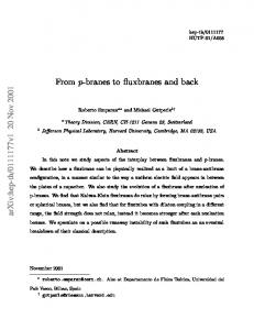
Figure 1: The MHV diagrams contributing to a one-loop MHV scattering amplitude. The blobs represent MHV vertices, which should then be dressed with external particles in all possible ways compatible with cyclic ordering, and in such a way that the two vertices have the MHV helicity configuration. Let us start illustrating this strategy by considering the simplest case, namely that of an MHV scattering amplitude at one loop.
3.1
One-loop MHV amplitude
The one-loop MHV diagrams contributing to an n-point MHV amplitude are presented in Figure 1. In our notation we only draw vertices and propagators (or cutpropagators) connecting them. It will be understood that we have to distribute the external gluons among the MHV vertices in all possible ways compatible with cyclic ordering, and the requirement that the two vertices must have the helicity configuration of an MHV amplitude. Moreover we will have to sum over all possible helicity 9
assignments of the internal legs and, where required, over all possible particle species which can run in the loop (what we are really drawing are the skeleton or quiver diagrams of [10, 34]). MHV
MHV
MHV
MHV
Figure 2: One-particle and two-particle MHV diagrams contributing to the one-loop MHV scattering amplitude. For the MHV amplitude we have to consider only one type of MHV diagram, represented in Figure 1, where two MHV vertices are connected by two Feynman propagators, which are both part of the loop. In Figure 2 we show the one-particle and two-particle cut diagrams which are produced in the application of the Feynman Tree Theorem. We start by focussing on one-particle cut diagrams. These one-particle cutdiagrams are nothing but tree-level diagrams, which are then integrated using a Lorentz invariant phase space measure. We now make the following important observation: these tree (one-cut) diagrams would precisely sum to a tree-level next-to-MHV (NMHV) amplitude with n + 2 external legs (which would then be covariant as shown in [2]), if we also include the set of diagrams where the two legs into which the cut propagator is broken are allowed to be at the same MHV vertex. Such diagrams are obviously never generated by cutting a loop leg in MHV diagrams of the type depicted in Figure 1. These “missing” diagrams are drawn in Figure 3. MHV rules tell us, before any phase space integration is performed, that the combined sum of one-particle cut diagrams of Figures 2 and 3 generates an NMHV amplitude with n + 2 external legs. Since the phase space measure is Lorentz invariant, we find that the sum of one-particle cut diagrams, including the missing diagrams, is covariant. -/+ MHV
MHV +/-
Figure 3: In this Figure we represent “missing diagrams”, mentioned in the text. It remains to justify the omission of these missing diagrams. We will present two alternative and somewhat complementary explanations. The first one relies on supersymmetry. The diagrams where two adjacent and opposite helicity legs from the same MHV vertex are sewn together vanish when summed over particle species in a supersymmetric theory. Individual diagrams before 10
summing over particle species diverge because of the collinearity of the momenta of the two legs, but the sum over particle species vanishes even before integration. So we discover that we could have actually included these diagrams from the start, since their contribution is zero. Hence one-particle cut diagrams of MHV one-loop amplitudes generate phase space integrals of tree-level NMHV amplitudes, and are, therefore, covariant. We now give a different explanation which does not rely on supersymmetry. Consider again the missing one-particle cut diagrams of Figure 3. Because of the delta function which cuts open one of the internal lines, these missing diagrams only need to be considered in a strict (anti-)collinear limit: if l is the cut loop momentum (l2 = 0), the two legs into which this is broken have momentum l1 = l and l2 = −l, respectively (the minus sign comes from the fact that all our momenta are considered as outgoing). Moreover, the two legs becoming (anti-)collinear always have opposite helicities, since they arise from cutting open an internal loop leg. In the anti-collinear limit, these missing diagrams are replaced by an expression which is a splitting function times a tree diagram with one less leg. Only one contribution is produced in this limit; this is because the leg, which in the limit replaces the two legs of momenta l1 and l2 , must always have negative helicity, otherwise the vertex to which it is attached would not have the configuration of an MHV vertex. These missing diagrams can then be rewritten as a splitting function times a sum of tree MHV diagrams with n + 1 external legs. Crucially, this sum of tree diagrams is precisely such that it combines into a tree-level (n + 1)-point amplitude, which is of course η-independent. So we conclude that the sum of the missing diagrams is actually separately η-independent, and hence the one-particle cut diagrams sum to a covariant expression. Having settled the one-particle cuts, we move on to consider two-particle cuts. These split the one-loop diagram of Figure 1 into two disconnected pieces (see the last diagram in Figure 2). These are two MHV amplitudes, because the two internal legs are put on shell by the Feynman cuts. Therefore, no η-dependence is produced by these two-particle cut diagrams. In conclusion, we have shown that Feynman one-particle and two-particle cut diagrams are separately covariant. Thus, by the Feynman Tree Theorem we conclude that the physical one-loop MHV amplitude is covariant too. Before moving to more complicated cases, let us highlight the following points, anticipating the general pattern which is emerging. 1. In a one-loop MHV diagram with v vertices and n external particles (contributing to an Nv−2 MHV amplitude), the top-cut we can make is necessarily the v-particle cut. This will always be η-independent by construction, similarly to the two-particle cut we have just considered for the one-loop MHV amplitude. Notice that this top cut will generically vanish if v > 4. 11
2. All p-particle cuts which are produced by the application of the Tree Theorem split each one-loop MHV diagram into p disconnected pieces when p > 1. In all such cases we see that amplitudes are produced on all sides of the cut propagators when the sum over all MHV diagrams is taken. 3. The case of a one-particle cut is special since it generates a connected tree diagram. Similarly to the case considered before, one realises that by adding missing diagrams the one-cut diagrams group into Nv−1 MHV amplitudes with n + 2 external legs (which are of course covariant). 4. To see amplitudes appearing on all sides of the cuts, one has to sum over all one-loop MHV diagrams. MHV
MHV
MHV
MHV
MHV
MHV
Figure 4: These are the MHV diagrams contributing to a one-loop NMHV scattering amplitude.
3.2
The NMHV amplitude at one loop
We now move on and consider the MHV diagrams contributing to a one-loop NMHV amplitude. These diagrams are drawn in Figure 4. The independent one-cut diagrams produced in the application of the Feynman Tree theorem are depicted in Figure 5; the missing diagrams, relevant in the study of one-particle cuts as explained earlier, are shown in Figure 6. It is easy to see that the one-particle cut diagrams of Figure 5 give, upon inclusion of the missing one-cut diagrams (drawn in Figure 6), an N2 MHV tree amplitude, which is covariant. Furthermore, two-particle cuts, represented in Figure 7, give an NMHV tree amplitude joined onto an MHV tree amplitude, and three-particle cuts give rise to three disconnected MHV amplitudes, each of which is covariant.
12
MHV
MHV
MHV
MHV
MHV
MHV
MHV
MHV
MHV
Figure 5: This Figure shows the one-particle cut diagrams generated by cutting open one loop propagator in the diagrams of Figure 4. Notice that the two diagrams on the right hand side are independent and should therefore be included separately. -/+ MHV
MHV
MHV +/-
MHV
MHV
+/-
MHV
-/+
Figure 6: Here we draw the missing diagrams corresponding to a NMHV scattering amplitude at one loop. These are one-particle diagrams which would never be generated by cutting open one loop propagator in the one-loop MHV diagrams of Figure 4.
3.3
The N2 MHV amplitude at one loop
We will conclude this section by considering the case of the N2 MHV amplitude at one loop. This case is general enough to serve as an illustration for more complicated cases, which can be treated in a completely similar fashion. The corresponding MHV diagrams are depicted in Figure 8. Upon applying the Feynman Tree Theorem, we will produce Feynman one-, two-, three- and four-particle cut diagrams. In complete similarity to the cases considered before, it is easy to see that: 1. The one-particle cut diagrams give, upon inclusion of the missing one-cut diagrams an N3 MHV tree amplitude with n + 2 external legs, which is covariant; 2. Two-particle cuts give rise to two different possibilities: either an N2 MHV and an MHV amplitude, or two NMHV amplitudes; 13
MHV
MHV
MHV
MHV
MHV
MHV
Figure 7: Two-particle cuts of an NMHV amplitude. 3. Three-particle cuts produce an NMHV amplitude and two MHV amplitudes; 4. Finally, four-particle cuts give rise to four disconnected MHV amplitudes which are trivially covariant. Again, each set of p-particle cut diagrams is covariant. As a consequence of the Feynman Tree Theorem, the sum of these sets reproduces the full physical amplitude, which is therefore covariant. A final comment before closing this section – so far we have not been working in any particular Yang-Mills theory; in particular, we have not required it to be supersymmetric. Therefore, the results of this section also show that the cut-constructible part of amplitudes in pure Yang-Mills computed using MHV diagrams is covariant. This is of course in agreement with the explicit results found in [28] for the particular case of MHV amplitudes.
4
General Structure of MHV diagrams at one loop
Having shown in the previous sections that the MHV method at one loop produces covariant expressions, we now show that general properties of one-loop MHV diagrams are in precise agreement with those arising from Feynman diagrams at one loop. In [13], Britto, Cachazo, Feng and Witten gave an elegant proof that MHV diagrams at tree level reproduce the corresponding amplitude computed from Feynman (n) (n) diagrams. Denoting by AMHV and AF the results of the MHV diagram and Feyn(n) man diagram calculations, the authors of [13] notice that AMHV has precisely the same (n) singularities (simple poles) as AF [2]. Of course a single MHV diagram taken in isolation contains additional unphysical poles coming from the presence of the reference ˙ momentum η. These singularities are of the form 1/hλi λP i where λaP := P aa η˜a˙ is 14
MHV
MHV
MHV
MHV
MHV
MHV
MHV
MHV
MHV
MHV
MHV
MHV
MHV
MHV
MHV
MHV
Figure 8: MHV diagrams contributing to a N2 MHV scattering amplitude at one loop. the spinor associated to an off-shell momentum P in the MHV diagram prescription, ˜ i . However, and the label i refers to a generic external particle, with momentum λi λ the sum of all tree-level MHV diagrams is covariant (i.e. η-independent), hence these (n) unphysical poles must cancel out in the sum AMHV [2, 13]. It then follows that the (n) (n) difference AF − AMHV must be a polynomial in the momenta of the particles. But scattering amplitudes of n gluons have dimension 4 − n; so for n > 4 the polynomial actually vanishes [13]. Explicit calculations settle the issue for the boundary case n = 4. The proof of the MHV diagrams method at one loop proceeds along similar lines – with the covariance of the amplitude at one loop being a cornerstone of the argument. (n) Firstly, we observe that by construction AMHV has precisely the same discontinuities of (n) AF . This is manifest in the calculation of the one-loop MHV amplitude of [4], where the two-particle cut of each one-loop MHV diagram contributing to the amplitude is directly mapped onto a (two-particle) unitarity cut of the same amplitude. For non-MHV amplitudes, one proceeds in a way similar to that discussed in previous sections. Consider a generic non-MHV amplitude computed using MHV diagrams at one loop. In order to study the discontinuity across a certain cut, fix the two propagators which correspond to that particular cut, and cut them. Then inspect all MHV diagrams contributing to the amplitude which have that particular two-particle cut. The next step consists in realising that the sum of these cut-MHV diagrams is 15
precisely equal to the two-particle unitarity cut of the amplitude we want to compute. Hence the discontinuity across that cut computed using MHV diagrams equals the physical discontinuity as computed from e.g. Feynman diagrams. By the same token it follows that all generalised cuts are also correct. Having shown that the MHV diagrams method gives covariant expressions with all the correct cuts (and generalised cuts), the last thing to show is that all the physical poles (collinear and multi-particle) are also correctly reproduced in an MHV diagram calculation. Assuming for the moment that this is the case (we will discuss this in the remainder of this section), then one could still argue that η-dependent terms might give rise to unphysical discontinuities or poles. A key point is therefore (n) to prove the covariance of the amplitude AMHV at one loop. But this is precisely what we have achieved in section 3. Therefore, no additional, unphysical singularities (n) can survive in an MHV diagram calculation at one loop. If the two functions AMHV (n) and AF have identical discontinuities and poles, then they must differ at most by polynomial terms. As in the tree-level proof of [13], such polynomial terms must vanish on dimensional grounds for n > 4. For n = 4, where such a polynomial could occur, the only non-vanishing one-loop amplitudes in supersymmetric Yang-Mills are the MHV amplitudes, computed in [4]. Hence, one would have proved that scattering amplitudes in supersymmetric Yang-Mills can be equivalently computed either with Feynman diagrams or with MHV diagrams. We will discuss collinear and soft limits in the following. In particular, we will demonstrate that amplitudes calculated with MHV diagrams have precisely the expected universal collinear factorisation properties. We do not have a proof of the correct multi-particle factorisation9 at this point; this would be the final piece needed to construct a complete proof of equivalence of Feynman and MHV diagrams. Given the non-trivial checks we will present below, we expect this to also follow upon further analysis. One important comment is in order here. We should make clear that the following considerations will apply to supersymmetric theories. The reason is that we will be able to reproduce expected physical poles of the amplitudes only in the presence of supersymmetry. It is indeed known that for non-supersymmetric Yang-Mills, a calculation based on MHV diagrams at one loop misses certain rational terms [34]. In [28] it was shown for the one-loop MHV amplitude in pure Yang-Mills that the cutconstructible part of the amplitude is correctly calculated. The arguments presented in this section indicate that this result extends to the case of any scattering amplitude in non-supersymmetric Yang-Mills – so that the cut-constructible part of non-MHV amplitudes in non-supersymmetric Yang-Mills can also be reliably computed using 9
The naive contributions to the multi-particle factorisation formula follow automatically from the MHV diagrams; the difficult piece is to reconstruct the correct one-loop factorisation functions. See e.g. [35] for a detailed discussion of one-loop multi-particle factorisation.
16
MHV diagrams.
4.1
Proof of universal collinear factorisation in the MHV diagrams method
Now we come back to the issue of reproducing the expected physical poles. We will first discuss in detail collinear limits of generic gluon amplitudes.10 Consider a one-loop scattering amplitude, An1−loop . When the massless legs a and b become collinear, the amplitude factorises as [5, 29, 35] akb
A1−loop (1, . . . , aλa , bλb , . . . , n) −−→ n X� 1−loop λa λb σ Splittree −σ (a , b ) An−1 (1, . . . , (a + b) , . . . , n)
(4.1)
σ
+
1−loop λa λb Split−σ (a , b )
Atree n−1 (1, . . . , (a
σ
�
+ b) , . . . , n) .
Splittree are the gluon tree-level splitting functions, whose explicit forms can be found e.g. in [51]; in particular, 1 1 , z(1 − z) ha bi 1 1 − − , Splittree + (a , b ) = − p z(1 − z) [a b] + + Splittree − (a , b ) = p
(4.2) (4.3)
with ka := zkP , kb := (1 − z)kP , and kP2 → 0, in the collinear limit. Split1−loop is a supersymmetric one-loop splitting function. In [37] and [38] explicit formulae for this one-loop splitting function, valid to all orders in the dimensional regularisation parameter ǫ, were found. We quote here the result of [38]:11 [1]
1−loop λa λb λa λb Split−σ (a , b ) = Splittree −σ (a , b ) r1 (z) ,
(4.4)
where, to all orders in ǫ, � � �� � � cΓ � −sab �−ǫ z z−1 [1] r1 (z) := 2 − 2 F1 1, −ǫ, 1 − ǫ, , 1 − 2 F1 1, −ǫ, 1 − ǫ, ǫ µ2 z z−1 (4.5) and Γ(1 + ǫ)Γ2 (1 − ǫ) . (4.6) cΓ := (4π)2−ǫ Γ(1 − 2ǫ) 10 11
Amplitudes with external fermions or scalars can be addressed in a completely similar fashion. The result of [37] is seen to be identical to that of [38] after using equations (A.9) and (A.10).
17
Notice that in (4.1) we sum over the two possible helicities σ = ±. It is the purpose of this section to reproduce (4.1), and in particular the all-orders in ǫ expressions (4.4) and (4.5), previously derived in [37, 38].
4.1.1
Collinear limits in the MHV diagrams approach at tree level
Collinear limits of amplitudes in the MHV diagram approach at tree level were already studied in the original paper [2], and found to be in agreement with the known results from Feynman diagrams. Multi-collinear limits were later analysed in [52,53]. Since the MHV diagram method is not manifestly parity symmetric, one needs to distinguish two types of collinear limits [2]: a. Collinear limits where the number of negative helicities is unchanged; these are the limits ++ → + and +− → −. b. Collinear limits where the number of negative helicities is reduced by one; these are −− → − and +− → +. In both cases, the MHV diagrams contributing to the collinear limit are only those where the two legs becoming collinear belong to the same MHV vertex [2]. However, in the cases a. and b. the singular behaviour – encoded in the tree-level splitting functions – arises from different types of MHV diagrams, as explained in section 4 of [2]. Collinear singularities of type a. are directly inherited from the MHV vertex to which the two legs becoming collinear are attached. On the other hand, collinear singularities of type b. arise from special kinds of MHV diagrams, namely those where the two legs becoming collinear are attached to a three-point MHV vertex (connected to another MHV vertex through a propagator which is going on shell in the collinear limit). The underlying reason why the splitting function for collinear limits of type b. arise in this peculiar way is that amplitudes with only one negative helicity vanish at tree level. As we shall see, at loop level the splitting functions for these two different cases also arise from different MHV diagrams. As illustrative examples for the two possibilities, we will study in detail the two collinear limits ++ → + (belonging to type a.) and −− → − (belonging to type b.) for a generic non-MHV amplitude. All other cases can be treated in an identical fashion and lead to the expected results. Our diagrammatic analysis will also explain the universal nature of collinear limits at one loop – a feature which emerges naturally in the MHV diagrams approach. We 18
will be able to derive expressions for the splitting functions to all orders in ǫ, matching previous results of [37, 38]. This is perhaps surprising – a priori one would expect to find expressions which are correct only in the four-dimensional limit, that is up to terms which vanish when ǫ → 0.
4.1.2
“Singular channel” and “non-singular channel” MHV diagrams
Before proceeding to analyse the two above-mentioned cases, we would like to discuss how the two terms in (4.1) arise in the MHV diagrams approach. What we are going to see is that, in some similarity with the unitarity-based derivation of [36], these two terms have a clearly separate diagrammatic origin: the first one arises from studying MHV diagrams where the kinematical invariant sab := (ka + kb )2 (with sab → 0 in the collinear limit) corresponds to a “non-singular” channel, the second from diagrams where sab is a “singular-channel”. We define singular channel MHV diagrams to be those where the following two conditions are satisfied (see Figure 9): 1. the two legs becoming collinear, a and b, belong to a four-point MHV vertex; 2. the remaining two legs of this four-point vertex (which are loop legs) are attached to the same MHV vertex. These diagrams are quite special, for the following reason [36]. By momentum conservation at the four point vertex, the condition sab → 0 implies that (L2 − L1 )2 := sL1 L2 → 0. When performing the loop integration, one encounters a region where the two loop legs L1 and L2 both go on shell, Li → li , with li2 = 0 (i = 1, 2). In this case, the condition sL1 L2 → 0 actually implies the collinearity of l1 and l2 . In the singular-channel diagrams, the two loop legs attached to the same MHV vertex, and this generates a further collinear singularity in the MHV vertex on the right-hand side.12 The conclusion of this discussion is that the collinear limit of these diagrams needs to be addressed with special care; importantly, the collinear limit sab → 0 must be taken before the four-dimensional one [36]. We will see in the specific calculation performed in the following that it is precisely diagrams of the singular type which give rise to the one-loop splitting function (the second term on the right hand side of (4.1)). Furthermore, we also notice that this particular class of diagrams gives rise to infrared-divergent contributions, as explained in [41]. Non-singular channel diagrams are those where the two legs a and b are a proper subset of the legs attached to a single MHV vertex, or those where a and b belong to a four-point MHV vertex A4,MHV (a, b, l2 , −l1 ) but the loop legs L1 and L2 are 12
For more details on this point we refer the reader to sections 2 and 3 in [36].
19
connected to different MHV vertices. In this case, even if L1 and L2 become null and collinear, nothing special happens to the sum of tree MHV diagrams on the right hand side of this four-point MHV vertex, precisely because L1 and L2 are not part of the same MHV vertex. For the very same reason, diagrams where the two legs becoming collinear belong to different MHV vertices do not develop collinear singularities. This important fact was noticed at tree level in [2], and the presence of a loop integration does not alter this conclusion. Therefore, we need not consider such diagrams in our analysis. We now move on to derive explicitly the collinear factorisation ++ → + and −− → − at one loop.
4.1.3
++ → + collinear limit at one loop
We start our discussion by considering diagrams where sab is a non-singular channel. Let Av,MHV (. . . , a+ , b+ , . . . , l2 , −l1 , . . .) be the MHV vertex to which the legs a+ and b+ are attached, which by assumption will be a v-point vertex with either v ≥ 5, or v = 4 and the two loop legs are connected to two different MHV vertices. When a+ and b+ become collinear, this vertex has the usual collinear singularity of a scattering amplitude akb
Av,MHV (. . . , a+ , b+ , . . . , l2 , −l1 , . . .) −−→ + + + Splittree − (a , b ) Av−1,MHV (. . . , (a + b) , . . . , l2 , −l1 , . . .) ,
(4.7)
which is not altered by the fact that l1 and l2 are analytically continued off the mass-shell. Summing over all MHV diagrams where sab is a non-singular channel, one immediately sees that a contribution identical to the first term in (4.1) is generated. This is because replacing Av,MHV (. . . , a+ , b+ , . . . , l2 , −l1 , . . .) with a loopindependent splitting function times Av−1,MHV (. . . , (a+b)+ , . . . , l2 , −l1 , . . .) gives that splitting function times a sum of one-loop MHV diagrams which precisely add up to + A1−loop n−1 (1, . . . , (a + b) , . . . , n). Next we move to the singular-channel diagrams (such as the one depicted in Figure 9), i.e. diagrams where the legs a and b belong to a four-point MHV vertex, and the two remaining loop legs are attached to the same MHV vertex. The diagram represented in Figure 9 is one of the one-loop MHV diagrams calculated in [4]. The fact that one or more of the legs attached to the MHV vertex on the right hand side attach to further vertices does not actually alter the calculation of [4]. Because a and b have positive helicity, only gluons can run in the loop. The 20
b
+ MHV 4pt
a
MHV
MHV
L2 MHV
MHV
+ L1 MHV
Figure 9: A schematic example of a one-loop MHV diagram contributing to a generic non-MHV one-loop amplitude where sab is a singular channel. In the collinear limit a k b, diagrams of this type generate the second term on the right hand side of (4.1). loop integrand involves the function [4, 5] ˆ := R
ha − 1 aihl2 l1 i hb b + 1ihl1 l2 i , ha − 1 l1ih−l1 ai hb l2 ih−l2 b + 1i
(4.8)
where the spinors l1 and l2 are those associated to the off-shell loop momenta L1 and L2 according to the prescription of [2],13 that is Li;α,α˙ = liα ˜liα˙ + zi ηα η˜α˙ ,
i = 1, 2 .
(4.9)
Notice that momentum conservation requires L2 − L1 + PL = 0, where in the singular channel PL = ka + kb . ˆ as Using the Schouten identity, we can recast R ˆ = −R(a, b) − R(a − 1, b + 1) + R(a, b + 1) + R(a − 1, b) , R
(4.10)
where R(i, j) is the homogeneous function of the spinors l1 and l2 given by R(i j) :=
hi l2 i hj l1 i . hi l1 i hj l2 i
(4.11)
We now rewrite the integrand in terms of the scalar functions appearing in the bubble, 13
In section 5.2 we briefly review this off-shell prescription, and also present two derivations of the one-loop integration measure of [4] to be used in calculating one-loop MHV diagrams such as the one in Figure 9. We refer the reader to that section, and to sections 3–5 of [4] for more details.
21
triangle and box integrals. Firstly, we notice that14 R(i j)
h
1 (1 2
− γ ) ˆi ˆl2 ˆj ˆl1 5
=
Tr hi l2 i [l2 j] hj l1 i [l1 i] = hi l1 i [l1 i] hj l2 i [l2 j]
=
(l1 i)(l2 j) + (l1 j)(l2 i) − (l1 l2 )(i j) . 2(l1 i)(l2 j)
4(l1 i)(l2 j)
i
(4.12)
Momentum conservation can be re-written in terms of l1 and l2 as [4] l2 − l1 + PL;z = 0 , with PL;z := PL − zη, and z := z1 − z2 . Using (4.13) we can rewrite � � 2 (ij) − 2(iPL;z )(jPL;z ) 1 (iPL;z ) 1 PL;z (jPL;z ) R(i j) = 1 + − + + . 2 (il1 ) (jl2 ) 4 (il1 )(jl2 )
(4.13)
(4.14)
Upon summing over the four terms in (4.10), bubbles (corresponding to the first term on the right-hand side in (4.14)) and triangle integrals (the term in square brackets in (4.14)) cancel, so we can replace the function R by an effective function Reff (i, j) containing only the contributions of the box functions, 2 (ij) − 2(iPL;z )(jPL;z ) 1 PL;z R (i, j; z) := . 4 (il1 )(jl2 ) eff
(4.15)
Specifically, these turn out to be two-mass easy box functions, that is box functions with two non-adjacent massless legs, i and j in (4.15), with the remaining two legs being massive. Furthermore, due to the identity 4(P i)(P j) − 2P 2 (ij) = (P + i)2 (P + j)2 − P 2 (P + i + j)2 := st − P 2 Q2 ,
(4.16)
valid for any momentum P , the function (4.15) is invariant under PL;z → PL;z + αi + βj ,
(4.17)
where α and β are arbitrary numbers. Thus, choosing η to be either i or j one can replace Reff (i, j; z) by Reff (i, j; 0). In [4] it was shown that each of the four terms in (4.10) (where, at this point, R can be replaced by Reff ) gives rise to a dispersion integral in the sab channel of the sab -cut of four different box functions – specifically, R(i, j) correspond to a twomass easy box with massless legs i and j. We would like to point out that η can be 14
In the following formula we will omit a term proportional to an ǫ-tensor contracted with four momenta, which vanishes upon integration.
22
chosen separately for each box function, so as to remove the η-dependence in the Reff function. Indeed in [4] it was shown (numerically) that η-dependence in the dispersion integral in one of the four channels of a certain box function cancels when combined with the integrals for the other three channels, for the terms which are singular and finite in ǫ.15 We have now extended this result by further verifying η-independence for the all orders in ǫ expression of the box function.
P q
p+1
q+1
p
Q Figure 10: The two-mass easy box function F 2me , whose all-order in ǫ expression is given in (4.18) and further studied in the Appendix. The vertical (horizontal) cuts correspond to the s-channel (t-channel) cuts, and the upper left (lower right) corner cuts to the P 2 -channel (Q2 -channel) cuts. The four terms in (4.10) give rise to four different boxes in the sab -cut, which are then integrated with the appropriate dispersive measure in the sab -channel (see section 5.2 and [4] for further details). Thus, what we are seeing here is that the one-loop collinear singularity arises precisely from summing these four dispersion integrals. A two-mass easy box is uniquely identified by specifying the two massless legs (see Figure 10 for the definition of the various kinematical invariants). For the four boxes in (4.10), the massless legs are I. a and b, II. a − 1 and b + 1, III. a and b + 1, IV. a − 1 and b. Now we make use of the following all-order in ǫ expression for the 15
So in fact at the final stage of performing all the dispersion integrals η can effectively be set to zero. Note, however, that for all previous stages of the calculation η has to be kept non-zero.
23
two-mass easy box function, also discussed in the Appendix,16 � � −t �−ǫ cΓ � −s �−ǫ 2me 2 2 F (s, t, P , Q ) = − 2 2 F1 (1, −ǫ, 1 − ǫ, as) + 2 F1 (1, −ǫ, 1 − ǫ, at) ǫ µ2 µ2 � � −P 2 �−ǫ � −Q2 �−ǫ � � 2 2 − .(4.18) − 2 F1 1, −ǫ, 1 − ǫ, aP 2 F1 1, −ǫ, 1 − ǫ, aQ µ2 µ2 Here a :=
P 2 + Q2 − s − t 2(pq) = , P 2 Q2 − st P 2Q2 − st
(4.19)
p and q are the two massless legs, and we have defined s := (P + p)2 ,
t := (P + q)2 .
(4.20)
The first contribution vanishes in the collinear limit, whereas the other three give a contribution cΓ � −sab �−ǫ h − 2 F1 (1, −ǫ, 1 − ǫ, aII sab ) + 2 F1 (1, −ǫ, 1 − ǫ, aIII sab ) ǫ2 µ2 i + 2 F1 (1, −ǫ, 1 − ǫ, aIV sab ) , (4.21) multiplied by a prefactor which is easily seen to be λa λb tree σ Splittree −σ (a , b ) An−1 (1, . . . , (a + b) , . . . , n) .
(4.22)
In (4.21) aI , . . . , aIV are the expressions for the parameter a defined in (4.19) appropriate for each of the four boxes. With ka := z(ka + kb ), kb := (1 − z)(ka + kb ) and (ka + kb )2 := sab → 0 in the collinear limit, we find that akb
aII sab −−→ 0 , akb
z , z−1
akb
z−1 . z
aIII sab −−→ aIV sab −−→ 16
(4.23)
The four-dimensional limit of (4.18), written explicitly in (A.8), was derived in [4] as the sum of four dispersion integrals (one for each cut of the box function) of appropriate phase space integrals. By keeping these phase space integrals to all orders in ǫ, one arrives at (4.18). As mentioned before, we have also performed extensive numerical checks that η dependence cancels between the four dispersion integrals even if we work with the all-order expressions of the phase space integrals. See the Appendix for further details on and alternative forms of the all-order in ǫ two-mass easy box functions, and section 5 of [4] for a discussion of the analytic continuation to the physical region of this expression.
24
Using 2 F1 (1, −ǫ, 1 − ǫ, 0) = 1, we can immediately re-write (4.21) as � � �� � � cΓ � −sab �−ǫ z z−1 + 2 F1 1, −ǫ, 1 − ǫ, , −1 + 2 F1 1, −ǫ, 1 − ǫ, ǫ2 µ2 z z−1 (4.24) [1] thus reproducing the function r1 (z) defined in (4.5), and hence the one-loop splitting function to all orders in ǫ, for the case of the collinear limit ++ → +.
4.1.4
−− → − collinear limit at one loop
As in the previous case, we can neatly separate the diagrams contributing to the treelevel splitting functions from those contributing to the one-loop splitting functions, first and second terms in (4.1), respectively. We begin by considering the diagrams contributing to the term in (4.1) containing the tree-level splitting function (see Figure 11). These are generated by those MHV diagrams where the legs becoming collinear, a− and b− , are joined to a three-point MHV vertex. This MHV vertex is then connected to the rest of the diagram. It is immediate to realise that, upon taking the 1−loop − − collinear limit, these diagrams give a contribution Splittree + (a , b ) An−1 (1, . . . , (a + b)− , . . . , n). MHV
ba-
MHV 3pt
MHV
MHV
MHV
Figure 11: A schematic example of a one-loop MHV diagram contributing to the non-singular channel diagrams for the −− → − collinear limit, giving rise to the 1−loop − − − contribution Splittree + (a , b ) An−1 (1, . . . , (a + b) , . . . , n).
We now move on to consider the diagrams which are at the origin of the term − Split1−loop (a− , b− ) Atree + n−1 (1, . . . , (a+b) , . . . , n). These diagrams, represented in Figure 12, are those where the negative-helicity gluons a− and b− are attached to a fourpoint MHV vertex. Furthermore, the remaining two legs of this vertex are connected to a three-point MHV vertex to form a loop. The remaining leg of this three-point MHV vertex is then attached to the rest of the diagram. The need for a threepoint vertex is due to the following fact. As the collinear limit is taken, the MHV 25
vertex on the left hand side produces a contribution ha bi3 which vanishes in the limit and would make the one-loop diagram vanish as well. The exception is when the second vertex is a three-point one; this is because the propagator attached to this vertex is in this case i/(ka + kb )2 . It is also clear that this mechanism is actually similar to that generating the tree-level splitting function with the same helicity 1−loop − − − − configuration, hence Split+ (a , b ) ∝ Splittree + (a , b ). Furthermore, by summing over all possible MHV diagrams which include such a sub-diagram we also produce a − term Atree n−1 (1, . . . , (a + b) , . . . , n). MHV
b
a
MHV 4pt
-
MHV 3pt
MHV
MHV
Figure 12: A schematic example of a one-loop MHV diagram contributing to the singular channel diagrams for the −− → − collinear limit, giving rise to the term − Split1−loop (a− , b− ) Atree + n−1 (1, . . . , (a + b) , . . . , n). The calculation of the diagram in question proceeds along lines very similar to that followed for the ++ → + collinear limit, so we will not spell it out. We would only like to point out one aspect of it which we believe is worth mentioning. In performing the algebra, one encounters ratios such as (ka k)/(kbk), where k is the null momentum associated to the internal leg attached to the three-point vertex, which carries momentum ka + kb . k is defined by the usual off-shell prescription ka + kb = k + zab η, from which k = ka + kb −
(ka kb ) η. (ka η) + (kb η)
(4.25)
It is then easy to see that
ka k kb η = , kb k ka η so that, in the collinear limit, such ratios give ka k akb (1 − z) (kP η) 1−z = , −−→ kb k z(kP η) z
(4.26)
(4.27)
where kP2 = (ka + kb )2 → 0 and ka = zkP , kb = (1 − z)kP in the collinear limit. Notice that k is null just because of the CSW prescription – that is independently of any collinear limit. 26
4.2
Soft limits of amplitudes with MHV diagrams
We now turn to discuss soft limits of amplitudes.
4.2.1
Tree level
Limits of amplitudes when the momentum of one of the particles goes to zero, i.e. soft limits, have a universal behaviour which is captured by soft functions (see e.g. [51]). At tree level, one has k →0
s tree Atree (a, s, b) Atree n (1, . . . , a, s, b, . . . , n) −−→ Soft n−1 (1, . . . , a, b, . . . , n) ,
(4.28)
where Softtree (a, s, b) is a tree-level soft (or eikonal) function, Softtree (a, s+ , b) =
ha bi , ha si hs bi
Softtree (a, s− , b) = −
[a b] . [a s] [s b]
(4.29)
It is easy to see that, at tree level, the MHV diagram method precisely reproduces the expected behaviour (4.28) for the amplitudes, with the soft functions given in (4.29). In similarity with the collinear limits, particular care is required when the soft gluon has negative helicity, and therefore the number of negative helicities is reduced by one. In this case, two diagrams are relevant for the process. The first one has an MHV three-point vertex with external particles a and s (s is the leg whose momentum is becoming soft), connected to an MHV vertex to which the leg b is attached so as to preserve the cyclic ordering a, s, b. The second diagram has s and b attached to a three-point MHV vertex, connected to a second MHV vertex to which a belongs. Summing up these two diagrams one obtains, in the soft limit, the second expression in (4.29).
4.2.2
One loop
The behaviour of one-loop scattering amplitudes when one of the legs becomes soft is quite similar to the collinear behaviour (see (4.1)), k →0
s An1−loop (1, . . . , a, s, b, . . . , n) −−→
Softtree (a, s, b) A1−loop n−1 (1, . . . , a, b, . . . , n) + Soft1−loop (a, s, b) Atree n−1 (1, . . . , a, b . . . , n) , 27
(4.30)
b
+ MHV
MHV
+
s
MHV 4pt
a
MHV
MHV
+ MHV
Figure 13: A schematic example of a one-loop MHV diagram contributing to the one-loop soft function Soft1−loop (a+ , s+ , b+ ). where Soft1−loop (a, s, b) is a one-loop soft function [54–59]. We will now obtain the all orders in ǫ expression for the one-loop soft function found in [38, 39], in the case where the helicities of the gluons a, s and b are all positive. MHV
MHV
b+ MHV 4pt
MHV
MHV
s+ a+
MHV
Figure 14: The second class of MHV diagrams contributing to Soft1−loop (a+ , s+ , b+ ). The relevant one-loop MHV diagrams are drawn in Figures 13-15. After performing the spinor algebra as in section 4.1, one can see that the term singular in the soft limit gives Soft1−loop (a, s, b) = Softtree (a, s, b) (BI + BII + BIII ) ,
(4.31)
where BI , BII and BIII are three dispersion integrals in the s, t and P 2 cut of a onemass box function with adjacent massless legs a, s and b. For this box, the parameter a defined in (4.19) is equal to a = −sab /(sas ssb ), with sij := (ki + kj )2 . Using the form (A.11) for the all-orders box function, where −asab /(1 − asab ) → 1 in the soft limit, along with πǫ , (4.32) 2 F1 (−ǫ, −ǫ, 1 − ǫ, 1) = sin(πǫ) 28
b +
MHV 4pt
s
a
MHV
MHV
+ MHV
MHV
+ MHV
Figure 15: The third class of one-loop MHV diagrams contributing to 1−loop + + + Soft (a , s , b ). we get Soft
1−loop
tree
(a, s, b) = Soft
�� � sab 2 �ǫ cΓ πǫ − µ . (a, s, b) − 2 ǫ sin(πǫ) sas ssb
(4.33)
This is in agreement with the results of [38, 39].
5
Further applications of the Feynman Tree Theorem
We have seen in previous sections that the Feynman Tree Theorem (2.19) leads us to consider various multiple cuts of a loop diagram. As reviewed in section 2, these cuts assign a specific sign to the energy of the cut line; using the “retarded” version of the theorem, the sign of the time components of all cut lines is negative, as prescribed by the second term in (2.7). By summing over these multiple cuts one obtains the physical amplitude – this is the content of the Feynman Tree Theorem, as expressed in (2.19). In this section we would like to present concrete examples of the application of the Feynman Tree Theorem. The first one is the calculation of a bubble diagram in a generic scalar theory, the second is the calculation of the one-loop MHV scattering amplitudes of [4].
29
5.1
Cutting bubbles with the Feynman Tree Theorem
Here we present a simple application of the Feynman Tree Theorem to the calculation of a bubble diagram. We will first evaluate it in a standard way, and then by applying the Feynman Tree Theorem.
Figure 16: A bubble diagram, which we firstly evaluate directly, and then by making use of the Feynman Tree Theorem. The two results are in perfect agreement. The bubble diagram we consider is represented in Figure 16, and is given by Z D d L 2 BF (K ) := ∆F (L) ∆F (L + K) f (L, K) , (5.1) (2π)D where ∆F are Feynman propagators, given in (2.4). We can think of (5.1) as a Feynman diagram in some scalar field theory; the function f (L, K) of the loop momentum L and external momentum K in the numerator of (5.1) is generated by the interaction vertices. The presence of this function is however irrelevant for the following discussion, thus we will set f = 1. We perform the integration in D = 4 − 2ǫ dimensions to regulate divergences in the integral (5.1); for ǫ 6= 0 the integration is convergent. Finally, notice that Lorentz covariance requires BF to be a function of K 2 .
5.1.1
Standard calculation of the bubble
We begin by first performing the L0 integration in (5.1). The Feynman propagators can be rewritten using (2.1). Therefore we see immediately that the integrand of (5.1) has four simple poles in the complex L0 plane, at the following locations: a. L0 = ωL − iε ,
b. L0 = −ωL + iε ,
30
(5.2)
c. L0 = −K0 − ωL+K + iε , where ωL :=
q
d. L0 = −K0 + ωL+K − iε ,
~ 2 + M 2. |L|
We see that the two poles a. and d. lie in the lower half L0 plane, whereas the remaining two are in the upper half L0 plane. We can close the integration contour with either a large semicircle above the real axis, or one below the real axis, each time enclosing two of the four poles. Choosing to close the contour below, we get � � BF = −2πi Resa + Resd , (5.3) where ~ dD−1 L lim (L0 − ωL + iε) ∆F (L) ∆F (L + K) (5.4) (2π)D L0 →ωL −iε � � Z D−1 ~ d L 1 1 i i 1 − , = 2π (2π)D−1 2ωL 2ωL+K K0 + ωL − ωL+K K0 + ωL + ωL+K − iε
Resa =
Z
~ dD−1 L lim (L0 + K0 − ωL+K + iε) ∆F (L) ∆F (L + K) (5.5) (2π)D L0 →−K0 +ωL+K −iε � � Z D−1 ~ 1 d L i 1 i 1 . − = 2π (2π)D−1 2ωL 2ωL+K −K0 + ωL+K − ωL −K0 + ωL+K + ωL − iε
Resd =
Z
Substituting (5.4) and (5.5) into (5.3) we get � � ~ dD−1L 1 1 1 AF , − (2π)D−1 ωL ωL+K −K0 − ωL − ωL+K + iε −K0 + ωL + ωL+K − iε (5.6) 17 which is our final result. It is easy to check that a calculation performed by closing the integration contour in the upper real plane leads to a result identical to (5.6). We will now re-derive this result using the Feynman Tree Theorem. i = 4
5.1.2
Z
The bubble reloaded: the Feynman Tree Theorem at work
The starting point is the identity Z D d L 2 BR (K ) := ∆R (L) ∆R (L + K) = 0 , (2π)D 17
(5.7)
For our purposes (5.6) will be sufficient; we will not need to perform the remaining integrations.
31
where ∆R are the retarded propagators of (2.2). The vanishing of the left hand side of (5.7) is an immediate consequence of the fact that all the poles of the integrand in the complex L0 plane lie below the real axis – specifically they are at ωL − iε, −ωL − iε, −K0 − ωL − iε, −K0 + ωL − iε. Closing the contour above, we see that BR = 0. We now use Feynman’s decomposition (2.7) for the two retarded propagators ∆R (L) and ∆R (L + K), π δ(L0 + ωL ) , ωL π ∆F (L + K) = ∆R (L + K) + δ(L0 + K0 + ωL+K ) , ωL+K ∆F (L) = ∆R (L) +
(5.8) (5.9)
and get an equation similar to (2.19), namely BF = B1−cut + B2−cut .
(5.10)
This is the Feynman Tree Theorem for the particular case of the bubble diagram. The one-particle cut contribution arises from picking either one or the other of the two delta functions in (5.8) or (5.9), and is (a)
(b)
B1−cut = B1−cut + B1−cut ,
(5.11)
with (a) B1−cut (b)
B1−cut
dD L iπ δ(L0 + ωL ) (2π)D ωL ωL+K
� 1 1 , − = (L0 + K0 ) − ωL+K + iε (L0 + K0 ) + ωL+K − iε � � Z D d L iπ δ(L0 + K0 + ωL+K ) 1 1 = , (5.12) − (2π)D ωL ωL+K L0 − ωL + iε L0 + ωL − iε Z
from which it follows that Z D−1 ~ d L 1 i B1−cut = 4 (2π)D−1 ωL ωL+K
�
�
1 1 − −K0 − ωL − ωL+K + iε −K0 + ωL + ωL+K − iε � − 2πi δ(ωL+K − ωL + K0 ) . (5.13)
Notice that (5.13) is equal to the result for BF obtained in (5.6) with standard methods except for an extra delta function contribution. In order to have agreement with (5.10), this additional term must be cancelled by B2−cut . Indeed, a direct calculation of this term gives Z D d L π π B2−cut = − δ(L0 + ωL ) δ(L0 + K0 + ωL+K ) D (2π) ωL ωL+K
32
π = − 2
Z
~ δ(K0 − ωL + ωL+K ) dD−1 L , (2π)D−1 ωL ωL+K
(5.14)
and it is immediately seen that (5.10) holds. In conclusion, we have seen that the application of the Feynman Tree Theorem expressed by (5.10) correctly reproduces the expected result (5.6) for the bubble integral.
5.1.3
A comment on Feynman two-particle cuts and unitarity cuts
Before concluding this section we would like to make a comment on the Feynman two-particle cuts, i.e. the two-particle cuts appearing when using the Feynman Tree Theorem, such as (5.14). It is important to realise that these are not the same as the conventional unitarity cut18 . The reason is that the Feynman Tree Theorem forces the sign of the time component of the two loop momenta in Figure 16 to be the same, specifically negative (positive) when using the decomposition of the Feynman propagator into a retarded (advanced) propagator and a delta function. The consequence is that this Feynman two-particle cut vanishes when K 2 > 0, if K 2 > 0 ,
B2−cut = 0 ,
(5.15)
therefore B2−cut cannot be a conventional unitarity cut, which does not vanish above the pair production threshold K 2 > 0. To prove (5.15), we notice that for K 2 > 0 we can choose a frame where K = (K0 , ~0). Then ωL = ωL+K , and the delta function in the last expression in (5.14) has support for K0 = 0; hence K is vanishing, contradicting the assumption K 2 > 0. ~ On the other hand, if K 2 < 0 we can choose a frame where K = (0, K). The delta function in (5.14) now has support for ωL = ωL+K , which admits the solution ~ = −K/2 ~ L (if K 2 = 0, dimensional regularisation requires that BF (K 2 = 0) must vanish).
5.2
Cutting one-loop MHV amplitudes with the Feynman Tree Theorem
Here we will apply the Feynman Tree Theorem to the one-loop calculation of an MHV scattering amplitude. 18
We mention however an interesting connection between the Feynman Tree Theorem and Cutkosky rules, described in section 7-3-3 of [71].
33
The relevant diagram is shown in Figure 17. From the point of view of the Feynman Tree Theorem, this calculation is similar to that for the bubble performed in the previous section. As in that case, Feynman’s theorem is used to decompose the two propagators which enter the one-loop integral, and the locality of the interaction makes it possible to apply the theorem in both approaches. The difference between the two calculations lies in the parametrisation of the loop momentum which is integrated over, as we discuss now.
5.2.1
The one-loop integration measure of [4]
To begin with, we will re-derive the integration measure which was used in [4] in order to calculate one-loop MHV scattering amplitudes with MHV vertices. The final result of this calculation, given in (5.47), will then be obtained in an alternative way by making use of the Feynman Tree Theorem. We choose a specific parametrisation for a generic off-shell momentum L [10, 72], L = l + zη ,
(5.16)
where l2 = 0, and η is a fixed and arbitrary null vector, η 2 = 0; z is a real number (in real Minkowski space). This choice of variables turns out to be particularly convenient for calculating one-loop amplitudes with MHV vertices [4]. Using (5.16), one can solve for z as a function of L, L2 z = . (5.17) 2(Lη) Using spinor notation, we write l and η as lαα˙ = lα ˜lα˙ , ηαα˙ = ηα η˜α˙ . It then follows that Lαα˙ η˜α˙ , [˜l η˜] η α Lαα˙ . = hl ηi
lα =
(5.18)
˜lα˙
(5.19)
(5.18) and (5.19) are equivalent to the CSW prescription proposed in [2] to determine the spinor variables l and ˜l associated with the non-null, off-shell four-vector L defined in (5.16).19 In [4] the integration measure d4 L over a generic loop momentum L was re19
The denominators on the right hand sides of (5.18) and (5.19) are irrelevant for applications, since the expressions we will be dealing with are homogeneous in the spinor variables lα .
34
expressed in terms of the new variables l and z introduced previously, with the result20 d4 L dz = dN (l) , L2 z
(5.20)
where we have introduced the Nair measure [73] � d3 l 1� 2˜ 2 ˜ ˜ hl dli d l − [l dl] d l = , dN (l) := 4i 2 l0
(5.21)
and l0 = (1/2)(l1˜l1˙ + l2 ˜l2˙ ) is the time component of the on-shell four-vector l := (l0 , ~l). It is important to realise that (5.21) does not contain any step function requiring the sign of the time-component l0 of l to be positive or negative; both possibilities l0 = ±|~l| are allowed.21 From (5.20) it follows that d4 L = dz
d3 l 2(lη) . 2 l0
(5.22)
Since both l and η are null it follows that sgn(lη) = sgn(l0 η0 ) (η0 is the time component of η), so that the Jacobian in (5.22) is positive if η0 > 0. We will assume this throughout this paper. Finally, we notice that d4 L dz = dN (l) , 2 L + iε z + i sgn(l0 η0 )ε
(5.23)
with dN (l) given by (5.21). In computing one-loop MHV scattering amplitudes from MHV diagrams (shown in Figure 17), the four-dimensional integration measure is [4] dM :=
d4 L2 (4) d4 L1 δ (L2 − L1 + PL ) , L21 + iε L22 + iε
(5.24)
where L1 and L2 are loop momenta, and PL is the external momentum flowing outside the loop22 so that L2 − L1 + PL = 0. Now we express L1 and L2 as in (5.16), Li;α,α˙ = liα ˜liα˙ + zi ηα η˜α˙ ,
i = 1, 2 .
(5.25)
Using (5.25), we rewrite the argument of the delta function as L2 − L1 + PL = l2 − l1 + PL;z ,
(5.26)
PL;z := PL − zη ,
(5.27)
where Q3 Here we define d4 L := i=0 dLi . 21 In Minkowski space we identify ˜l = ±l∗ depending on whether l0 is positive or negative. 22 In our conventions, all external momenta are outgoing. 20
35
and z := z1 − z2 .
(5.28)
Notice that we use the same η for both the momenta L1 and L2 . Using (5.25), we can re-cast (5.24) as [4] � 3 � dz1 d l1 d3 l2 (4) dz2 dM = δ (l2 − l1 + PL;z ) , (5.29) z1 + iε1 z2 + iε2 2l10 2l20 where εi := sgn(η0 li0 )ε = sgn(li0 )ε, i = 1, 2 (the last equality holds since we are assuming η0 > 0). Notice also that no step functions for l10 or l20 have appeared so far.
L2 PL
MHV
MHV
L1
Figure 17: MHV diagrams contributing to a one-loop MHV scattering amplitude. In the text we show that these diagrams can equivalently be computed either by a direct calculation, as in [4], or by resorting to the Feynman Tree Theorem. We can now convert the integration over z1 and z2 in (5.29) to an integration over z defined in (5.28), and z ′ defined by z ′ := z1 + z2 .
(5.30)
Indeed [4], neither the measure nor the integrand depend on z ′ , which can therefore be integrated out. To do this, we observe that dz dz ′ dz2 dz1 → 2 ′ . z1 + iε1 z2 + iε2 (z + z + iε1 )(z ′ − z + iε2 )
(5.31)
The previous expression viewed as a function of z ′ has two simple poles, located at −z − iε1 and z − iε2 . To carry out the z ′ integration, we must discuss in detail the iε prescriptions. 2 We begin by first assuming that PL;z > 0. We can then go to the rest frame of PL;z , where PL;z = a(1, ~0) for some real number a. Momentum conservation requires
l1 =
a (1, n ˆ) , 2
l2 = 36
a (−1, n ˆ) , 2
(5.32)
where n ˆ is a unit vector. Note that the time components of l1 and l2 have opposite signs. These signs are determined by the sign of a or, stated in an invariant way, by the sign of the time component (PL;z )0 of PL; z (recall that the sign of the time component of a time-like vector is a proper Lorentz invariant). We can furthermore make the replacement d3 l1 d3 l2 (4) δ (l2 − l1 + PL;z ) → − dLIPS(l2− , −l1+ ; PL;z ) , 2l10 2l20
(5.33)
where dLIPS(l2− , −l1+ ; PL;z ) := d4 l1 δ (+) (l12 ) d4 l2 δ (−) (l22 ) δ (4) (l2 − l1 + PL;z )
(5.34)
is the two-particle Lorentz invariant phase space (LIPS) measure, and we recall that δ ± (l2 ) := θ(±l0 )δ(l2 ). 2 It is crucial that at PL;z > 0, ε1 and ε2 have opposite signs. By closing the integration contour with a large semicircle in the upper (or lower) z ′ complex plane, one always picks the contribution of one pole. We first assume the sign of the time component of PL;z to be positive, a > 0. Remember that εi := sgn(li0 η0 ); having assumed η0 > 0, we see that
(PL;z )0 > 0 ⇒ ε1 > 0 ,
ε2 < 0 .
(5.35)
Performing the z ′ integration by closing the contour either above or below one gets 2
dz dz ′ dz → 2πi . ′ ′ (z + z + iε1 )(z − z + iε2 ) z + iε
(5.36)
Therefore from (5.29) we get dM|P 2
L;z >0; (PL;z )0 >0
= − 2πi
dz dLIPS(l2− , −l1+ ; PL;z ) . z + iε
(5.37)
What happens if we choose a < 0, i.e. (PL;z )0 < 0? There are two differences compared with the case above. The first one is (PL;z )0 < 0 ⇒ ε1 < 0 ,
ε2 > 0 ,
(5.38)
and the result of the z ′ integration is now dz dz ′ dz 2 ′ → 2πi . ′ (z + z + iε1 )(z − z + iε2 ) −z + iε
(5.39)
Secondly, we have now d3 l1 d3 l2 (4) δ (l2 − l1 + PL;z ) → − dLIPS(l2+ , −l1− ; PL;z ) . 2l10 2l20 37
(5.40)
Hence one would obtain dM|P 2
L;z >0; (PL;z )0 0 (l10 < 0). Finally, we observe that one can trade the z integration for an integration over 2 2 PL;z . After a little algebra, one finds that for PL;z >0 2 dPL;z dz = . 2 z sgn (PL;z )0 + iε −PL;z + PL2 + iε
(5.46)
In conclusion, the integration measure (5.44) gives dM = 2πi
2 θ(PL;z )
2 PL;z
2 dPL;z dLIPS(l2∓ , −l1± ; PL;z ) , 2 − PL − iε
(5.47)
which is our final result. A few comments are in order here. 2 1. As (5.47) shows, the integration is performed for PL;z > 0. By setting all the 2 various external kinematical invariants PL to be negative, no poles are encountered
38
along the integration contour, and the iε prescription can be dropped. This is what had been done in [4]. However (5.47) provides us with the correct analytic continuation to the physical region, which is obtained by simply performing the substitution PL2 −→ PL2 + iε .
(5.48)
In [4] a new form of the two-mass easy box function was derived, simpler than the usual form. One of the advantages of this expression was precisely that its analytic continuation in a physical region is achieved by simply performing the naive replacement dictated by (5.48). 2. A comment may be made on the phase space measure appearing in (5.47). This instructs us to include both possibilities l10 = |l~1 |, l20 = −|l~2 |, and l10 = −|l~1 |, l20 = |l~2 |. We can swap the sign of l0 by simply replacing ˜l → −˜l, where lαα˙ := lα ˜lα˙ . MHV vertices do not contain dotted spinor variables, hence it is not necessary to distinguish between the cases l10 > 0 and l10 < 0. Taking this into account, we can simply choose e.g. l10 > 0 and multiply the final result by a factor of two. 3. The integration measure dM as it is expressed on the right hand side of (5.47) can immediately be dimensionally regularised, by simply replacing the fourdimensional LIPS measure of (5.34) by its continuation to D = 4 − 2ǫ dimensions, dD LIPS(l2− , −l1+ ; PL;z ) := dD l1 δ (+) (l12 ) dD l2 δ (−) (l22 ) δ (D) (l2 − l1 + PL;z ) .
(5.49)
4. Eq. (5.47) was one of the key results of [4]. It gives a decomposition of the original integration measure into a phase space measure and a dispersive measure. From Cutkosky’s theorem [70] we know that the LIPS measure computes the discontinuity of a Feynman diagram across its branch cuts. Which discontinuity is evaluated is determined by the argument of the delta function appearing in the LIPS measure; in (5.47) this is PL;z (defined in (5.27)). Finally, discontinuities are integrated using the dispersive measure in (5.47), thereby reconstructing the full amplitude.
5.2.2
Re-derivation of the measure of [4] with the Feynman Tree Theorem
Here we show that the integration measure (5.47) can equivalently be derived by applying the Feynman Tree Theorem directly to the measure (5.29). This provides a check of the consistency of our prescriptions. We start off by considering the Feynman one-particle cuts. When we cut the leg with momentum L2 we replace it by its on-shell version with momentum l2 , and the integration measure d4 L2 /(L22 + iε) is replaced by what is prescribed by the second 39
term in (2.7); dividing by a factor of i (since in (5.29) we had omitted factors of i in the propagators), we have from (2.19) that the once-cut measure is obtained by making the replacement d4 L2 d3 l2 4 (−) 2 . (5.50) → −2πi d L2 δ (L2 ) = 2πi L22 + iε 2l20 l20 =−|l~2 |
The once-cut contribution to the integration measure arising from cutting L2 is therefore � 3 � d l1 d3 l2 (4) dz1 δ (l2 − l1 + PL; z1 ) . (5.51) dM|L2 −cut = 2πi z1 + iε1 2l10 2l20 l20 0 in (5.51), and ε2 > 0 in (5.53). In this case, (5.51) becomes
dM|L2 −cut;P 2
L;z >0
dz dLIPS(l2− , −l1+ ; PL;z ) , z + iε
(5.54)
dz dLIPS(l2+ , −l1− ; PL;z ) . − z + iε
(5.55)
= −2πi
whereas (5.53) gives dM|L1 −cut;P 2
L;z >0
= −2πi
2 For PL;z > 0, (5.54) and (5.55) are already in agreement with the measure (5.44) (or (5.45)); hence we expect that, in this regime, the two-particle cuts should not contribute. This would indeed completely parallel the example of the bubble addressed in an earlier section.
But before moving to the two-particle cuts, let us complete the study of the 2 Feynman one-cuts, by considering the regime PL:z < 0. Here momentum conservation requires that, both in (5.51) and (5.53), one must have l10 < 0 and l20 < 0. Hence
40
2 ε1 and ε2 have the same (negative) sign. It follows that at PL;z < 0 the net effect of (5.51) and (5.53) is given by a common phase space measure, multiplied by
1 1 + = 2iπδ(z) . z − iε −z − iε
(5.56)
Integrating out z using the delta function, one obtains dM1−cut P 2