JOURNAL OF LIGHTWAVE TECHNOLOGY, VOL. 21, NO. 11, NOVEMBER 2003
2617
An Optical IM/FSK Coding Technique for the Implementation of a Label-Controlled Arrayed Waveguide Packet Router K. Vlachos, J. Zhang, J. Cheyns, Sulur, Nan Chi, E. Van Breusegem, I. Tafur Monroy, J. G. L. Jennen, P. V. Holm-Nielsen, C. Peucheret, R. O’Dowd, Senior Member, IEEE, P. Demeester, Senior Member, IEEE, and A. M. J. Koonen, Senior Member, IEEE
Abstract—In this paper, we present a new concept of optical packet/burst switching suitable for generalized multiprotocol label switched (GMPLS)-based optical networks. In such networks, optical labeled switched Paths are being established in a similar way as label-switched paths in MPLS. We use a wavelength label as well as an orthogonally modulated label, with respect to the payload modulation format, and which is encoded using either frequency-shift keying (FSK) or differential phase-shift keying (DPSK). Wavelength is used for switching in the node, whereas the orthogonal label defines the label-switched path. We present both simulation and experimental results to assess transmission performance of the proposed combined modulation scheme. In addition, we propose a suitable optical node architecture that can take advantage of this stacked label concept. Toward this, we use widely tunable wavelength converters to efficiently route IM/FSK (or IM/DPSK) optically labeled packets in an arrayed-waveguide grating (AWG)-based node structure. We present performance simulation results in terms of packet loss ratio and internal block probability. Internal blocking is an inherent problem of AWG optical routers, and a specific wavelength assignment algorithm has been developed to minimize it. Finally, the feasibility of IM/FSK transmission is experimentally demonstrated over an 88-km single-mode fiber span, and novel aspects of FSK generation and detection techniques are presented. Index Terms—Arrayed waveguide grating (AWG), differential phase-shift keying, frequency shift keying, GCSR laser, generalized multiprotocol label switched (GMPLS), optical packet/burst switching.
Manuscript received December 3, 2002; revised February 12, 2003. This work was supported in part by the European Union under the IST-STOLAS project, which is supported in part by the IST Program of the European Commission. The work of E. Van Breusegem was supported by IWT. K. Vlachos and J. G. L. Jennen are with Bell Laboratories Advance Technology EMEA, 1200BD Hilversum, The Netherlands (e-mail: kvlachos@ lucent.com). J. Zhang, N. Chi, P. V. Holm-Nielsen, and C. Peucheret are with COM Institute, Technical University of Denmark, Lyngby, Denmark (e-mail:
[email protected]). Sulur, I. T. Monroy, and A. M. J. Koonen are with COBRA Institute, Eindhoven University of Technology (e-mail:
[email protected]). J. Cheyns, E. Van Breusegem, and P. Demeester are with Department of Information Technology, Ghent University, Gent, Belgium (e-mail:
[email protected]). R. O’Dowd is with Optoelectronics Research Centre, University College Dublin, Ireland. Digital Object Identifier 10.1109/JLT.2003.819143
I. INTRODUCTION
D
ESPITE the recent slowdown of the telecommunications market, R&D teams worldwide are trying hard to develop the technology and the systems that will allow the industry to offer cost-effective and reliable solutions to the end-user. The emergence of wavelength-division multiplexing (WDM) technology has unlocked most of the available bandwidth, reducing costs per bit, which can be expected to further fuel the demand for bandwidth. However, dense WDM does not hold all the answers. The increasing transmission rates will eventually shift the bottleneck from the transport back to the switching nodes. Indeed, current switching technologies are capable of switching at rates of “only” 1–10 Gb/s. While emerging ATM switches and IP routers can be used to switch data using the individual channels (typical rates of 2.5 or 10 Gb/s) within a WDM link, this approach requires tens or even hundreds of switch interfaces to terminate a single link with a large number of channels. Moreover, there can be a significant loss of statistical multiplexing efficiency when the parallel channels are used simply as a collection of independent links, rather than as a shared resource. Optical packet and burst switching [1]–[4] has been introduced as the main concept to overcome these limitations and fully exploit bandwidth capacity, in a cost-effective way, taking advantage of statistical multiplexing in the sense that packets use outgoing capacity on demand. Statistical multiplexing is especially useful to cope with the burst nature of traffic in data-centric networks. This is in contrast to time-division-multiplexed (TDM) circuit switches that assume regular, periodic traffic, and fixed allocation of packet slots to circuits. Several innovative packet switch architectures have been proposed so far, including switches with recirculating loops [5], the staggering switch [7], the switch with large optical buffers (SLOB) [8], the wavelength routing switch and the broadcast (WRS), and select switch (BSS) [9]. However, work on new architectural concepts, node performance, and intelligent control have lagged behind progress in transmission speeds. Switches with recirculating loops were the first optical packet switches to address the high bandwidth and buffering issues [5]. This solution, however, increases switch block complexity, switch with delay lines for buffering, insince for an , an space switch is stead of an required. The staggering switch was the first optical switch designed to truly emulate an output-buffered switch [6], [7].
0733-8724/03$17.00 © 2003 IEEE
2618
Although very promising and influential, this design exhibits unnecessary packet delays and unsatisfactory packet loss characteristics for bursty traffic. Reduction of the packet loss rate for bursty traffic is achieved by cascading many small output-buffered switches, consequently increasing costs, to arrive at a larger buffer depth. The SLOB is an example of such a design [8]. Renaud et al. [9] detailed two WDM shared output-buffered packet switching architectures, WRS and BSS, that were developed through the ACTS Keys to Optical Packet Switching project. The WRS is a two-stage switch that first buffers conflicting packets before routing them to their desired output, where a tunable wavelength converter is used to route packets to the appropriate delay line and output port respectively [10]. Although the WRS is an improvement of the staggering switch by being nonwasting, it suffers from the same scalability and modularity issues. In the BSS [11], fast semiconductor optical amplifier (SOA) gates are used to select the appropriate packets at each output for each time slot [12]. The BSS architecture is also “nonwasting” and one of the few proposed architectures that can easily provide multicasting. In addition, it can be used as the building block in a multistaged switch [13] to allow for a modular growth, up to several hundreds of switch I/Os. Apart from the architectural issue, it is also of paramount importance to efficiently encode routing/switching information for each optical packet or burst of packets. Up to now, two main approaches have been investigated: bit-serial and parallel multiplexing of the header—hereinafter called label—and the payload data. Bit-serial multiplexing, however, imposes stringent processing requirements in the nodes, especially when the label rate is high and is extremely bandwidth wasting when the label rate is low [10], [14], [15]. Parallel multiplexing techniques are more promising and yield significant advantages when applied to optical packet bursts. The label data are at a significantly lower rate and separated in frequency from the payload. The advantage of having out-of-band labels on a separate (control) wavelength, as already adopted in [3], is the capability to separate the switching from the control plane, allowing easy label data extraction, detection, and processing and providing a quick and efficient single forwarding algorithm based on label swapping. In addition, a serious amount of high-speed O/E/O converters is avoided, as payload data are delayed until the end of the electronic processing. Up to now, subcarrier multiplexing (SCM) has been investigated as a possible implementation option of parallel payload-label multiplexing [16]–[18]. To this end, label information is multiplexed on a radio-frequency signal, generating two symmetrical optical tones around the center optical frequency. However, fiber dispersion and fiber nonlinearities such as cross-phase modulation (XPM) and four-wave mixing (FWM) [19] or carrier fading due to polarization maintaining dispersion (PMD) [20] may generate significant amounts of crosstalk between adjacent SCM channels since they are very closely spaced. In this paper, we present a new concept of optical packet/burst switching using two level optical labels. That is a wavelength label and an orthogonally modulated label, with respect to payload modulation format, and which is coded using either frequency-shift keying (FSK) or differential phase-shift keying
JOURNAL OF LIGHTWAVE TECHNOLOGY, VOL. 21, NO. 11, NOVEMBER 2003
(DPSK). This scheme is supported by the generalized multiprotocol label switched (GMPLS) protocol, by which optical label-switched channels can be established in a similar way as the electronic label-switched paths (LSPs) in the MPLS protocol [21]. The orthogonal label carries the data information that identifies the LSP, while wavelength is used for switching within the node. In addition, we propose a label-controlled node architecture that can take advantage of this stacked label concept. This node design efficiently integrates widely tunable wavelength converters and arrayed waveguide gratings and is capable of performing routing and switching functions based on the information encoded either in the wavelength and/or orthogonal label [22], [24]. The rest of this paper is organized as follows. Section II presents the label-controlled optical router, and qualitative performance results are given in terms of packet loss ratio and internal blocking probability. Furthermore, a specific wavelength assignment algorithm has been developed to cope with the internal blocking problem of the arrayed-waveguide grating (AWG)-based node structures. Section III discusses the transmission performance of the proposed combined modulation formats (IM/FSK and IM/DPSK) with emphasis on the implementation of an IM/FSK transmission link. Finally, Section IV presents novel aspects on the implementation of optical FSK transmitters, and results of an IM/FSK transmission experiment over an 88-km SMF span. II. LABEL-CONTROLLED ARRAYED WAVEGUIDE GRATING ROUTER The setup of the label-controlled packet router is shown in Fig. 1. Both the wavelength and the orthogonal (DPSK or FSK) wavelength channels on label of the bursts in each of the input fibers are examined at each node. After each of the their inspection, the appropriate optical path is set along which the packet payload data are forwarded transparently. New labels are reinserted for each burst, using a two-level integrated optical swapper [22], [23]. Subsequently, depending on the converted wavelength, each packet is directed to the appropriate output via the arrayed waveguide grating [25], [26]. Special wavelength labels can be reserved for buffering, multicasting, and dropping inpurposes. A router handling wavelengths and having label swappers folcoming/outgoing links requires AWG. In such a lowed by a ports of the AWG are reserved for adding packets design, additional ports for multicasting. Similar functionality and and can be achieved in a more modular way, e.g., in an node by incorporating three 4 4 AWGs [24] or even 2 2 AWGs [27]. For two-level label swapping, a Mach–Zehnder interferometer (MZI) with two SOAs in its branches will be used, in combination with a tunable laser at its input [24]. The incoming intensity-modulated payload/label data are transferred to a new wavelength by means of wavelength conversion via cross-phase modulation. As the cross-phase modulation in the SOAs is driven by the intensity modulation of the incoming packet, and not by its phase modulation, the optical DPSK or FSK label of the label is erased. To this end, a new wavelength label is set
VLACHOS et al.: OPTICAL IM/FSK CODING TECHNIQUE FOR WAVEGUIDE PACKET ROUTER
Fig. 1.
2619
The label-controlled optical packet router setup.
and at the same time the orthogonally modulated label of the packet is removed. In addition, in the case of FSK labeling, a new FSK label is generated by modulating the phase section of the tunable laser as described in Section IV-A, whereas in the case of DPSK labeling, a new DPSK label is generated using an additional phase modulator. Of crucial importance for node designs based on AWGs is their high blocking probability, which results in increased packet losses [28]. In order to assess its performance, we developed a wavelength assignment algorithm that finds the optimal wavelength converter settings for every active input port arriving at the highest possible throughput through the routing node. The algorithm [29] is based on a simplified node mode (see Fig. 2), where we consider only input and output fibers. In switches were considered, addition, only symmetrical bearing in mind that each incoming and outgoing link in reality will have the same number of operational wavelengths. The operation of this simplified model can be represented in a table structure, as displayed in Fig. 3(a). This figure shows the input/output connectivity, whereas the elements of the table denote the wavelength used. In other words, the table shows which wavelength drives a packet from a specific input port to a specific output port. However, the incoming fibers carry a subset of eight wavelengths ( to ) and therefore the wavelengths shown in gray in Fig. 3(a) are not used. For example, a packet entering the node via port 1, requesting output port 0, must be wavelength converted to , which is not used. This results in internal blocking of the switch, with various probabilities depending on how the AWG output ports are combined. Fig. 3(b) shows two such output port combinations versus wavelength for . The elements in both tables denote the input output fiber port that is connected via a certain wavelength (row) to a cer-
Fig. 2.
Simplified model of the AWG packet router.
tain output port (column). In that way, the blocking behavior of the node is easily seen by checking the rows of each table. For example, in the case of the bottom table of Fig. 3(b), a packet ; or, from incoming port 4 cannot be routed to output fiber in the case of the upper table of Fig. 3(b), packets arriving from or in input ports 0, 2, and 4 have to be converted to either order to be routed to output . However, since the three signals are multiplexed together in one output fiber, they should be on different wavelengths. This implies that one of the packets has to be dropped. In order to evaluate the severity of the internal blocking and the impact of the configuration of the output ports, we applied our wavelength assignment algorithm [29]. For the development of the algorithm, synchronous operation with fixed length packets is assumed. To this end, packets that are present on the input ports are all synchronized in time, which allows identification of the simultaneously active incoming links for applying the wavelength assignment algorithm. The method is based on the maximum matching algorithm [30], according to which the problem is translated in
2620
JOURNAL OF LIGHTWAVE TECHNOLOGY, VOL. 21, NO. 11, NOVEMBER 2003
Fig. 3.
Table representation of the AWG router behavior.
a graph problem for every output fiber separately by creating a bipartite graph as follows. Every input port is represented by a node, as is every wavelength. An edge is present between an input port node and a wavelength when a conversion of the signal on that input port to that wavelength arrives in the considered output fiber. Finding the maximum throughput then corresponds to finding a maximum matching in the graph. Using this algorithm, four output port configurations were simulated and presented in the is the number sequence. is the number of input fibers and of wavelengths. , • T1: Output fiber contains ports ; this is simply grouping the output ports ordered, as displayed by Fig. 2. However, as previously mentioned, this is certainly not a good configuration, as some ports cannot be switched to a certain output fiber. contains ports , • T2: Output fiber and . with , . • T3: Output fiber contains ports contains output • T4 is a derivative of T3: Output fiber and , , ports . To the rest of the output ports, the remaining fibers are assigned in a round robin way. So the remaining outputs contain the ports for which mod , where stands for the remaining AWG output . ports, renumbered to We calculated for all the aforementioned configurations the packet loss ratio due to the blocking probability of the switch. For this, we assumed both contending and noncontending traffic with a Poisson arrival distribution. Destinations of the packets are considered uniform, in the sense that all destinations are evenly likely. In contending traffic, more bursts than the number of wavelengths are allowed to be destined to the same output fiber. The contrary holds for noncontending traffic. The simulation was carried out for a three-fiber, 12-wavelength switching node, and thus, a 36 36 AWG is assumed. Fig. 4 displays the packet loss probability in function of the applied load for the four different output port configurations in the case of noncontending traffic. With noncontending traffic the difference between the four configurations is more evident. It is worth noticing that for an ideal nonblocking switch the packet loss ratio with this traffic pattern must be zero. From
Fig. 4. Loss probability for a three-fiber 12-wavelength switching node with noncontending traffic.
Fig. 4 it can be seen that configuration T1 results in a constant high packet loss ratio. This is due to the inability of input ports 0, 12, and 24 to reach two of the three output fibers. All other input ports are blocked from one of the output fibers. So, a loss is found. probability of These calculations are in fact underestimates of the actual loss, since there are other situations that can lead to additional loss. However, the loss related to internal blocking is so high that extra loss has no visible effect on the overall performance. The same also applies for two fibers and four wavelengths, where or input port 0 could never input port 4 could never reach [see Fig. 3(a)]. reach On the contrary, configuration T4 results in the lowest blocking probability. This has an intuitive explanation: as in a very regular table structure, several ports tend to have the exact same (sub)set of possible wavelengths, so they behave exactly the same and are thus very strongly coupled. If this coupling is weakened, it is possible to make better wavelength choices for the different input ports, resulting in a lower loss probability. The coupling is then in fact more randomly smeared out over the input ports. We must note here that it is impossible to find an output port combination that completely overcomes internal blocking. The general conclusion, however, is that a very irregular structure is preferable. Similar simulations were carried out for contending traffic, and Fig. 5 displays the corresponding packet loss ratios as a
VLACHOS et al.: OPTICAL IM/FSK CODING TECHNIQUE FOR WAVEGUIDE PACKET ROUTER
Fig. 5. Loss performance of a three-fiber 12-wavelength switching node and allowing contention.
function of the applied load for fiber combinations T1..T4. It is worth noticing here that the behavior of the AWG-based switch, when combined with the maximum matching wavelength assignment algorithm, lies very close to that of an ideal nonblocking switch (ideal curve in Fig. 5). Therefore, it is important that the output ports are combined using a good wavelength assignment algorithm, which results in a very low blocking probability. This can also be seen when random wavelength assignment is enforced (random curve in Fig. 5), which results in higher packet loss ratios. Finally, Fig. 6 displays the packet loss ratio change when more (or less) wavelengths are added for the switch to accommodate more (or less) traffic. Furthermore, the increase in the number of wavelengths is necessary in order to decrease the high packet loss ratios that such AWG-based node architectures exhibit. As a rule of thumb, a loss ratio of less than 10E-6 would be acceptable. III. COMBINED IM/FSK AND IM/DPSK PAYLOAD/LABEL MODULATION FORMAT In the two-level label scheme we are proposing, the wavelength label determines the forwarding operation of the AWG router while a second label contains more detailed information for the label-switched path. The second-level label is orthogonally modulated to the payload’s amplitude modulation, e.g., angle modulation. Angle modulation schemes enable the control information to modulate the phase or frequency of the optical carrier. The labeling process is illustrated in Fig. 7. The high-speed payload data are transmitted using intensity modulation, while moderate-speed label data are transmitted on the same optical carrier by angle modulation. FSK labeling can be obtained by direct current modulation of the laser, whereas an external phase modulator is required in case of DPSK labeling. Then the payload information and label information can be detected using different demodulation techniques at the receiving end. Such an optically labeled signal has a compact spectrum and has shown its robustness in the label-swapping node [22]. Due to their capabilities in the direct detection scheme, both DPSK and FSK are attractive candidates for the modulation format of the second label. In fact, the feasibility of combined intensity modulation and angle modulation has been previously
2621
Fig. 6. Loss probability for a three-fiber switching node with varying number of wavelengths per fiber.
Fig. 7.
Optically labeled signal generation.
demonstrated in an experimental WDM network [36]. However, a coherent detection scheme was employed in those experiments. In this section, we will investigate the performance of combined IM/PSK and IM/FSK formats in labeled signal transmission links employing a direct detection scheme. For the combined modulation format, an optimal IM extinction ratio should be obtained in such a way that both the payload and label data can be correctly detected. By increasing the IM extinction ratio, the sensitivity of the payload IM receiver is improved, but the sensitivity of the FSK (or DPSK) receiver is degraded. We assess the performance of both combined modulation schemes by simulating transmission links employing direct detection for the IM and FSK data and a balanced detection scheme for the DPSK data. Fig. 8 shows the schematic diagram of the simulated link with the IM/FSK and IM/DPSK transceivers. The receiver sensitivity for the IM and the FSK (or DPSK) receiver is defined as the average received power to achieve a bit error ratio (BER) of 10 and 10 , respectively. The BER of the label receiver is required to be much better than the one of the payload receiver, as routing errors will cause the loss of many packets, whereas bit errors may be corrected by upper link layer protocols. Residual amplitude modulation due to direct FSK modulation of the laser source for combined IM/FSK format is included in the simulations. In both transmission links, the payload data are 1 pseudorandom bit sequence (PRBS) pattern running at 2 10 Gb/s, whereas the label data are 2 1 PRBS at 155 Mb/s. Fig. 9 displays the sensitivity change of IM, FSK, and DPSK receivers versus the IM extinction ratio for various transmission links. In the case of FSK, a tone separation of 20 GHz and an FSK-induced residual intensity modulation of 0.46 dB are assumed. In addition, laser linewidths of 100 and 2.5 MHz are assumed for FSK and DPSK, respectively. From Fig. 9, it
2622
Fig. 8.
JOURNAL OF LIGHTWAVE TECHNOLOGY, VOL. 21, NO. 11, NOVEMBER 2003
Schematic diagram of (a) IM-payload/FSK-label and (b) IM-payload/DPSK-label transmission link.
Fig. 9. Receiver sensitivity change against payload extinction ratio for various transmission links. (i) IM/FSK combined modulation format. a = 10 km, b = 15 km, c = 18 km for IM, and d = 10; 15; 18 km for FSK. (ii) IM/DPSK combined modulation format. a = 20; 40; 60 km for IM and b = 20; 40; 60 km for DPSK.
can be seen that the IM/DPSK combined format can achieve a transmission distance of 60 km of typical SMF without any significant receiver sensitivity degradation, whereas IM/FSK can only achieve a transmission distance of 15 km. This is due to the walkoff between the FSK tones spaced at 20 GHz. Apart from the IM extinction ratio, another important parameter is the laser linewidth. We simulated a 60-km fiber link for different laser linewidths. Fig. 10 displays the calculated receiver sensitivities at the aforementioned BER values, in the case of 50- and 100-MHz linewidths for FSK and 2.5, 5, and 7 MHz linewidths for DPSK. For reasons of comparison, 9.6 km of dispersion compensating fiber was added in the case of FSK to compensate for the
dispersion of the 60-km standard SMF link. It is evident that DPSK data detection imposes stringent requirements on the laser linewidth, while FSK can tolerate much higher values. The optimum IM extinction ratio for the combined IM/FSK format is about 7–8 dB, while for the combined IM/DPSK format, values close to 8 and 7 dB were found for laser linewidths of 2.5 and 5 MHz, respectively. The overall sensitivity of the label and payload receiver can be optimized, adjusting the optical coupler ratio [22]. From the above discussion, we may conclude that IM/FSK offers a significant advantage over IM/DPSK as a payload/ label coding option. Despite limitations imposed by dispersion, its simplicity in terms of creation/detection and laser linewidth re-
VLACHOS et al.: OPTICAL IM/FSK CODING TECHNIQUE FOR WAVEGUIDE PACKET ROUTER
2623
=
Fig. 10. Receiver sensitivity change against IM payload extinction ratio for various laser linewidth values. (i) IM/FSK combined modulation format. a 50; 100 MHz for IM, b = 50; 100 MHz for FSK, c = 50, 100 MHz overall. (ii) IM/DPSK combined modulation format. a = 2:5; 5; 7 MHz for IM, b = 2:5 MHz for DPSK, c = 5 MHz for DPSK, d = 7 MHz for DPSK, e = 2:5 for MHz overall, f = 5 MHz overall, g = 7 MHz overall.
Fig. 11.
Grating coupler with rear sampled reflector (GCSR) laser.
quirements makes IM/FSK the preferred implementation option. In addition, with an optimized dispersion compensation scheme, extended transmission distances can be expected. On the contrary, implementation of IM/DPSK requires an MZ interferometer with a single bit delay at the receiver, which may severely impact performance due to potential instability.
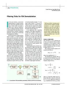
IV. IMPLEMENTATION AND PERFORMANCE EVALUATION OF AN IM/FSK TRANSMISSION LINK In this section, we present results of an IM/FSK transmission experiment over an 88-km SMF span. In addition, we present the potential implementation of an FSK transmitter using a GCSR laser. Due to their wide tunability, a single device can be used for wavelength label swapping operation as well as for generation of the required, symmetrical FSK label. A. FSK Transmitter Implementation Using GCSR Laser In this section we show that the desired FSK tone spacing can be achieved with a low FSK modulation index and a high side-mode suppression ratio. We used a four-section monolithic
InGaAsP/InP laser from ADC-Altitun S.A.1 Fig. 11 displays the laser structure, showing a gain section followed by a vertical codirectional coupler, a phase section, and a sampled distributed Bragg reflector section [31]. In such lasers, the modulated Bragg reflector section provides a comb of peaks and the codirectional coupler can select any of these. The emitted wavelength depends on the refractive index difference of the coupler filter. Continuous wavelength tuning is achieved by adjusting all currents applied to reflector, coupler, and phase sections. Coarse tuning is performed with only the coupler section current. This gives a wavelength “band” that is accessible by the other tuning currents. Within this wavelength band, the reflector section current tunes the lasing wavelength to the exact desired frequency. Fine tuning is performed with the phase section current to ensure a high side-mode suppression ratio (SMSR). Tuning to a particular frequency requires simultaneous adjustment of all three tuning currents. Fig. 12(a) displays the combination of currents, required to obtain the different emission frequencies of 41 ITU channels on a 100-GHz grid. The output power variation and SMSR for each of the 41 channels is 1http://www.adc.com/Library/Literature/100 064.pdf
2624
JOURNAL OF LIGHTWAVE TECHNOLOGY, VOL. 21, NO. 11, NOVEMBER 2003
Fig. 12. (a) Current combinations to obtain the 41 ITU channels. The gain section current is set to 101.7 mA. (b) Output power and side-mode suppression ratio variation.
shown by Fig. 12(b). The average output power is about 2 mW and the average SMSR is close to 40 dB, with a variation of 25% and 12%, respectively. The channel-to-channel power variation, however, can be significantly reduced if the gain section current is also detuned [32]. It can also be observed that the output power increases for low tuning currents due to the shift of the lasing mode toward the gain maximum, whereas for high tuning currents, the output power decreases due to free-carrier absorption. Finally, it is worth noticing that the power dips in Fig. 12(b) exactly coincide with the maximum reflector current values in Fig. 12(a). For the implementation of FSK, frequency detuning with a low modulation index and a high SMSR must be achieved. This requirement can only be met by modulation of the phase current. To this end, the label signal will modulate the phase section and data will be encoded on the two generated optical tones. It has been found that a maximum detuning of 60 GHz could be obtained by phase current modulation only [39]. In our case, a frequency deviation of 10 GHz would be adequate for sufficient filtering of the label/payload data at the receiver [24]. However, for specific ITU channels, the corresponding phase currents were too small [see Fig. 12(a)], prohibiting modulation. This can be overcome by adjusting the reflector currents to higher values, achieving the required 10 GHz frequency detuning for almost all ITU channels. Fig. 13 displays the corresponding phase section currents required for 10 GHz detuning away from the center ITU wavelengths. Fig. 14 displays the modified as well as the original values of the reflector current for setting the ITU channels. In an ideal optical FSK transmitter, the power difference between the two tones is negligible as a result of low modulation indexes. We have measured the power variation of the FSK tones in a static way as well as the corresponding phase current difference for a total 20-GHz symmetrical detuning. Fig. 15 displays the results. The side-tones for a sample channel at 195.2 THz are shown in Fig. 16. This result indicates that 30 dB “intertone suppression” is possible with this device. However, in this case the FSK switching square-wave was merely 1 MHz. As this modulation rate rises, the intertone dip rises to a plateau; this is believed to result from a combination of drive pulse risetime and the mea-
Fig. 13. Phase section currents to achieve ITU wavelength channels.
Fig. 14.
610 GHz detuning for each of the
Modified and original values of I per ITU wavelength channel.
surement response. A fast apparatus [38] with 150-ps risetime is being adapted to verify this [39]. Control of the frequency for the 195.2-THz channel is illustrated in Fig. 17. Frequency control from 191.167 to 192.227 THz, a range of 60 GHz, is achieved under slow tuning of the phase current. So, FSK tones at 10 GHz will be well within the safe operating region that avoids mode-hopping. This is imminent at the extreme ends of the range so that a guard region is desirable around the center bias point. The
VLACHOS et al.: OPTICAL IM/FSK CODING TECHNIQUE FOR WAVEGUIDE PACKET ROUTER
2625
Fig. 17. Static frequency characteristic at a selected channel indicating a potential 60-GHz sweep for FSK around 195.2 THz. Fig. 15. Power variation and corresponding phase current difference of FSK optical tones for each ITU wavelength channel. Gain current is set to 101.7 mA.
Fig. 18. I versus I plane with grayscale for optical frequency detailing behavior at the 195.2-GHz channel.
Fig. 16. FSK modulation at 195.2 THz (device ADC-972) showing 30-dB intertone suppression. Horizontal scale 31 GHz/div.
static versus current plane is displayed for this device in Fig. 18, where the grayscale represents optical frequency. We can infer from the shape of the modal regions (horizontal “stripes” within which continuous tuning is achieved) why this particular device has superior FSK ability. For other devices these modal spans are more curved, arcs rather than horizontals, and phase current tuning alone reaches a boundary sooner. In such cases, the reflector section current needs to be adjusted as well to drive the laser along an arc between mode boundaries, adding to drive complexity. On the same point, we note that bias and center this study reveals the importance of careful current selection for the FSK sweep in order to always ensure a well-centered dc bias for each channel. This in turn may require modification of the normal lookup table for the ITU grid when FSK labeling is to be deployed in conjunction with packet wavelength identification. In conclusion, FSK coding can be implemented with GCSR lasers applying the right current combination. Easy application of the correct current combination is obtained by mounting the laser chip with a microprocessor, programmed with a control protocol and a specific set of data pertinent to the laser. These data will correspond to a certain combination of currents for selecting the ITU channel, while external modulation of the phase current will provide the desired frequency deviation. Further study will address the modulation bandwidth of the specific section current [33], [34], [39].
B. An FSK-Labeled Signal Transmission Link To verify the feasibility of the optical FSK labeling scheme, an 88-km SMF transmission link was set up as shown in Fig. 19. Within this context, the wavelength label and the signal data rates were randomly chosen. The optically labeled signal, consisting of a 10-Gb/s payload and a 312-Mb/s label, was first generated, then transmitted over 88-km SMF, and finally detected using direct detection receivers. Two pseudorandom pat1 PRBS payload tern generators were used to generate a 2 pattern at 10 Gb/s and a 2 1 PRBS label pattern at 312 Mb/s. The transmitter was based on a directly modulated DFB laser, operating at 1555 nm, integrated with an electroabsorption modulator. This setup can be used as a simple alternative to a GCSR laser for FSK label generation in case wavelength tunability is not required. The FSK tone spacing was set to 20 GHz. The DFB direct modulation at 312 Mb/s generates two asymmetric optical tones, in the sense that the FSK signal is combined with residual amplitude shift keying (ASK). However, by driving the electroabsorption modulator with the conjugate data signal from the electrical channel of the pattern generator, the residual ASK modulation is removed and a symmetrical FSK detuning around 1555 nm can be obtained [37]. Payload data were added using a 10-Gb/s chirp-free Mach–Zehnder intensity modulator (MZM). Fig. 20 shows the optical spectrum of the direct modulated DFB laser at 312 Mb/s (pure FSK) as well as the IM/FSK spectrum after the payload modulation with the MZM. In the sequence, the labeled signal is amplified to 10 dBm and launched into the fiber. The transmission span consisted of 88-km SMF and a matching length of dispersion compensating fiber (DCF). The
2626
Fig. 19.
JOURNAL OF LIGHTWAVE TECHNOLOGY, VOL. 21, NO. 11, NOVEMBER 2003
Experimental setup for the transmission of the orthogonally labeled IM/FSK signal.
Fig. 20. Optical Spectrum (in a 0.01-nm resolution bandwidth) at the output of the DFB/EA laser (pure FSK) and at the output of MZ modulator (FSK/IM).
DCF was inserted into the link based on a hybrid dispersion compensation map (i.e., its length was split equally before and after the transmission fiber) to give optimized transmission performance. At the receiver node, the labeled signal was split using a 3-dB optical coupler. One of the outputs was directly detected by a photodiode, and thus the optical payload was converted into the electrical domain. In the other arm, a fiber Bragg grating (FBG) was used to filter out a single tone of the FSK labeled signal, thus achieving demodulation. An electrical receiver with 1.8-GHz bandwidth was used for the detection of the demodulated label data. The suppression ratio between the two optical tones was measured after the FBG and was found to be 20 dB. Fig. 21 displays the eye diagrams of the labeled signal after transmission. As the simulation results predict, crosstalk is introduced between the payload and the label. The received label eye diagram has a multi-level structure due to the amplitude modulation of the payload as can be seen in Fig. 21(b). The extinction ratio of the payload is a determining
Fig. 21. Eye-diagram of the received (a) 10-Gb/s payload (horizontal scale: 20 ps/division) and (b) 312-Mb/s label (horizontal scale: 1 ns/division).
factor of the labeling process. Fig. 22(a) illustrates the relation between the measured receiver sensitivities of the payload and label and the extinction ratio of the payload in the back-to-back case. The sensitivities are evaluated at a BER of 10 . From this figure, it is found that a good tradeoff between the label and payload performance can be achieved with nearly 6-dB extinction ratio. Fig. 22(b) shows the BER curves measured for the payload and the label when the payload extinction ratio is equal to 6 dB. The transmission penalties for label DCF span are 2.2 and and payload after the 88-km SMF 1.2 dB, respectively. These experimental results indicate that the combined IM/FSK modulation scheme can be a promising candidate for optical labeling, while its performance should be improved further for the purpose of practical applications.
VLACHOS et al.: OPTICAL IM/FSK CODING TECHNIQUE FOR WAVEGUIDE PACKET ROUTER
2627
COBRA Institute—Eindhoven University of Technology, COM Institute—TU Denmark, ADC Altitun, Telenor, Hymite, and Lucent Technologies. REFERENCES
Fig. 22. (a) Payload and label receiver sensitivity versus payload extinction ratio of the payload and (b) BER performance of the optically labeled signal.
V. CONCLUSION In this paper, we presented a new concept of encoding label and payload data suitable for both optical burst- and packet-switched networks. In this approach, label information is encoded in FSK format, while the payload is encoded in typical IM format. Both FSK data and wavelength are treated as labels and are used for routing/switching in a GMPLSbased network, identifying the label-switched path. We also discussed and analyzed a suitable node architecture based on arrayed waveguide gratings that can accommodate the proposed combined modulation format. For this, we developed a wavelength assignment algorithm to cope with its inherent blocking probability. Finally, we investigated the feasibility of obtaining the FSK detuning using widely tunable GCSR lasers and experimentally demonstrated FSK/IM transmission over an 88-km SMF span. Based on the simulated and experimental results, we conclude that the combined FSK/IM modulation scheme can be a promising solution for optical labeling. Its performance can be further improved, using GCSR lasers as wavelength tunable FSK transmitters and by optimizing dispersion to cope with the tones walkoff. ACKNOWLEDGMENT The authors would like to acknowledge the contributions of their colleagues from University College Dublin, IMEC,
[1] D. Colle, S. De Maesschalck, C. Develder, P. Van Heuven, A. Groebbens, J. Cheyns, I. Lievens, M. Pickavet, P. Lagasse, and P. Demeester, “Data-centric optical networks and their survivability,” IEEE J. Select. Areas Commun., vol. 20, no. 1, pp. 6–20, 2002. [2] S. Yao, B. Mukherjee, and S. Dixit, “Advances in photonic packet-switching: An overview,” IEEE Commun. Mag., pp. 84–93, Feb. 2000. [3] C. Qiao and M. Yoo, “Optical burst switching (OBS) – A new paradigm for an optical internet,” J. High Speed Networks (Special Issue on WDM Networks), vol. 8, no. 1, pp. 69–84, Jan. 1999. [4] J. S. Turner, “WDM burst switching for petabit data networks,” in Optical Fiber Communication Conf. 2000, vol. 2, 2000, pp. 47–49. [5] A. Huang and S. Knauer, “Starlight: A wideband digital switch,” in Proc. IEEE Global Telecommun. Conf. (GLOBECOM’84), vol. 1, Nov. 1984, pp. 121–5. [6] Z. Haas and D. R. Cheriton, “Blazenet: A packet-switched wide-area network with photonic data path,” IEEE Trans. Commun., vol. 38, pp. 818–829, June 1990. [7] Z. Haas, “The ‘staggering switch’: An electronically controlled optical packet switch,” J. Lightwave Technol., vol. 11, pp. 925–936, May-June 1993. [8] D. Hunter et al., “SLOB: A switch with large optical buffers for packet switching,” J. Lightwave Technol., vol. 16, pp. 1725–1736, Oct. 1998. [9] M. Renaud, F. Masetti, C. Guillemot, and B. Bostica, “Network and system concepts for optical packet switching,” IEEE Commun. Mag., vol. 35, pp. 96–102, Apr. 1997. [10] C. Guillemot, M. Renaud, P. Gambini, C. Janz, I. Andonovic, R. Bauknecht, B. Bostica, M. Burzio, F. Callegati, M. Casoni, D. Chiaroni, F. Clerot, S. L. Danielsen, F. Dorgeuille, A. Dupas, A. Franzen, P. B. Hansen, D. K. Hunter, and A. Kloch, “Transparent optical packet switching: The European ACTS KEOPS project approach,” J. Lightwave Technol., vol. 16, pp. 2117–2134, Dec. 1998. [11] D. Chiaroni, P. Bonno, O. Rofidal, J. C. Jacquinot, P. Poignant, C. Coeurjoly, F. Fernandez, E. Mestre, J. L. Moncelet, A. Noury, A. Jourdan, T. Zami, A. Dupas, M. Renaud, N. Sahri, D. Keller, S. Silvestre, G. Eilenberger, S. Bunse, W. Lautenschlaeger, and F. Masetti, “First demonstration of an asynchronous optical packet switching matrix prototype for multiterabit class routers/switches,” in Proc. ECOC’01, vol. 6, pp. 60–61. [12] S. Khalfallah, A. Dupas, B. Martin, D. Herrati, S. Fabre, N. Tscherptner, P. Peloso, I. Guillemot, J. L. Bris, M. Renaud, L. Gilbert, D. Penninckx, A. Gdth, C. Saboureau, D. Baillargeat, C. Moussam, C. Aupetit-Berthelemot, and J.-M. Dumas, “Optical packet switching with lossless 16-channel InP monolithically integrated wavelength selector module,” Electron. Lett., vol. 38, no. 19, pp. 1124–1125, 2002. [13] F. Masetti, M. Sotom, D. De Bouard, D. Chiaroni, P. Parmentier, F. Callegati, G. Corazza, C. Raffaelli, S. L. Danielsen, and K. E. Stubkjaer, “Design and performance of a broadcast-and-select photonic packet switching architecture,” in Eur. Conf. Optical Communication, vol. 3, 1996, pp. 309–312. [14] B. E. Olsson, P. Öhlén, L. Rau, G. Rossi, O. Jerphagnon, R. Doshi, D. S. Humphries, D. J. Blumenthal, V. Kaman, and J. E. Bowers, “Wavelength routing of 40 Gbit/s packets with 2.5 Gbit/s header erasure/rewriting sing all-fiber wavelength converter,” Electron. Lett., vol. 31, no. 4, pp. 345–347, Feb. 2000. [15] D. Hunter, M. Nizam, M. Chia, I. Andanovic, K. Guild, A. Tzanakaki, M. O’Mahony, J. Bainbridge, M. Stephens, R. Penty, and I. White, “WASPNET: A wavelength switched packet network,” IEEE Commun. Mag., pp. 120–129, Mar. 1999. [16] A. Carena, M. D. Vaughn, R. Gaudino, M. Shell, and D. J. Blumenthal, “OPERA: An optical packet experimental routing architecture with label swapping capability,” J. Lightwave Technol., vol. 16, pp. 2135–2145, Dec. 1998. [17] I. Chlamtac et al., “CORD: Contention resolution by delay lines,” IEEE J. Select. Areas Commun., vol. 14, pp. 1014–1029, June 1996. [18] K. V. Shrikhande, I. M. White, D. Wonglumsom, S. M. Gemelos, M. S. Rogge, Y. Fukashiro, M. Avenarius, and L. G. Kazovsky, “HORNET: A packet-over-WDM multiple access metropolitan area ring network,” IEEE J. Select. Areas Commun., vol. 18, pp. 2004–2016, Oct. 2000.
2628
JOURNAL OF LIGHTWAVE TECHNOLOGY, VOL. 21, NO. 11, NOVEMBER 2003
[19] H. Rongqing, Z. Benyuan, H. Renxiang, C. T. Allen, K. R. Demarest, and D. Richards, “Subcarrier multiplexing for high-speed optical transmission,” J. Lightwave Technol., vol. 20, pp. 417–427, Mar. 2002. [20] O. H. Adamczyk, A. B. Sahin, Q. Yu, S. Lee, and A. E. Willner, “Statistics of PMD-induced power fading for double sideband and single side-band subcarrier-multiplexed signals,” in Proc. OFC’01, Anaheim, CA, MO5. [21] N. Ghani, “Lambda-labeling: A framework for IP-over-WDM using MPLS,” Opt. Networks Mag., pp. 45–58, Apr. 2000. [22] T. Koonen, G. Morthier, J. J. Jennen, H. de Waardt, and P. Demeester, “Optical packet routing in IP-over-WDM networks deploying two-level optical labeling,” in 27th Eur. Conf. Optical Communication 2001, vol. 4, 2001, pp. 608–609. [23] D. J. Blumenthal, B.-E. Olsson, G. Rossi, T. E. Dimmick, L. Rau, M. Masanovic, O. Lavrova, R. Doshi, O. Jerphagnon, J. E. Bowers, V. Kaman, L. A. Coldren, and J. Barton, “All-optical label swapping networks and technologies,” J. Lightwave Technol., vol. 18, pp. 2058–2075, Dec. 2000. [24] Sulur, T. Koonen, I. T. Monroy, H. de Waardt, J. Jennen, and G. Morthier, “Combined ASK/FSK and ASK/DPSK modulation formats for optically labeled signals,” in Proc. ONDM’2002, Torino, Italy, Feb. 4–6, 2002. [25] S. L. Danielsen, B. Mikkelsen, C. Joergensen, T. Durhuus, and K. E. Stubkjaer, “WDM packet switch architectures and analysis of the influence of tunable wavelength converters on the performance,” J. Lightwave Technol., vol. 15, pp. 219–227, Feb. 1997. [26] E. Zouganeli, A. F. Mlonyeni, A. Sudbo, O.-P. Rostad, and T. Olsen, “Wavelength routed network using widely tunable transmitters,” in Proc. ECOC’2000, Munich, Germany, Sept. 3–7, 2000. [27] A. Sudbø, S. Bjørnstad, and E. Zouganeli, “Scalable optical switch based on tunable wavelength converters and arrayed waveguide grating routers,” presented at the OFC’2003. [28] S. L. Danielsen, C. Joergensen, B. Mikkelsen, and K. E. Stubkjaer, “Analysis of a WDM packet switch with improved performance under bursty traffic conditions due to tuneable wavelength converters,” J. Lightwave Technol., vol. 16, pp. 729–735, May 1998. [29] J. Cheyns, C. Develder, E. Van Breusegem, A. Ackaert, M. Pickavet, and P. Demeester, “Routing in an AWG based optical packet switch,” Photon. Network Commun., vol. 5, no. 1, pp. 69–80, Jan. 2003. [30] G. Chartrand and O. P. Oellermann, Applied and Algorithmic Graph Theory. New York: McGraw-Hill, 1975, pp. 161–204. [31] B. Broberg, P. J. Rigole, S. Nilsson, M. Renlund, and L. Andersson, “Widely tunable semiconductor lasers,” IEEE/LEOS Soc. Annu. Meeting, vol. 2, pp. 151–152, 1998. [32] H. Debrégeas-Sillard, A. Vuong, F. Delorme, J. David, V. Allard, A. Bodéré, O. LeGouezigou, F. Gaborit, J. Rotte, M. Goix, V. Voiriot, and J. Jacquet, “DBR module with 20-mW constant coupled output power, over 16 nm (40 50-GHz spaced channels),” IEEE Photon. Technol. Lett., vol. 13, pp. 4–6, Jan. 2001. [33] G. Morthier, G. Sarlet, R. Baets, R. O’Dowd, H. Ishii, and Y. Yoshikuni, “The direct modulation bandwidth of widely tunable DBR laser diodes,” in IEEE Semiconductor Laser Conf., 2000, pp. 87–88. [34] Y. Yonglin and R. O’Dowd, “Influence of mode competition on the fast wavelength switching of an SG-DBR laser,” J. Lightwave Technol., vol. 20, pp. 700–704, Apr. 2002. [35] H. Nakajima and J. Charil, “Time-resolved spectrum characteristics of FSK-modulated dual-mode DFB/DBR lasers,” IEEE Photon. Technol. Lett., vol. 9, pp. 821–823, June 1997. [36] M. Hickey and L. Kazovsky, “The STARNET coherent WDM computer communication network: Experimental transceiver employing a novel modulation format,” J. Lightwave Technol., vol. 12, pp. 876–884, May 1994. [37] J. Zhang, N. Chi, P. V. Holm-Nielsen, C. Peucheret, and P. Jeppesen, “A novel optical labeling scheme using a FSK modulated DFB laser integrated with an EA modulator,” presented at the Optical Fiber Communication Conf. (OFC’03), 2003.
2
[38] R. O’Dowd, S. O’Duill, G. Mulvihill, and Y. Yu, “Frequency plan and wavelength switching limits for widely tunable transmitters,” IEEE J. Select. Topics Quantum Electron., vol. 7, pp. 259–269, Mar./Apr. 2001. [39] S. O’Duill, G. Mulvihill, Y. Yu, and R. O’Dowd, “FSK modulation labeling performance of WDM C-band lasers for packet routing,” , submitted for publication.
K. Vlachos, photograph and biography not available at the time of publication.
J. Zhang, photograph and biography not available at the time of publication.
J. Cheyns, photograph and biography not available at the time of publication.
Sulur, photograph and biography not available at the time of publication.
Nan Chi, photograph and biography not available at the time of publication.
E. Van Breusegem, photograph and biography not available at the time of publication.
I. Tafur Monroy, photograph and biography not available at the time of publication.
J. G. L. Jennen, photograph and biography not available at the time of publication.
P. V. Holm-Nielsen, photograph and biography not available at the time of publication.
C. Peucheret, photograph and biography not available at the time of publication.
R. O’Dowd (SM’95), photograph and biography not available at the time of publication.
P. Demeester (SM’98), photograph and biography not available at the time of publication.
A. M. J. Koonen (SM’01), photograph and biography not available at the time of publication.