INTRODUCTION. System-on-a-Chip (SoC) technology requires design of using ... Architect [4] or SoC Designer [5], puts emphasis on SoC design, ... Android [9].
2009 Fifth International Conference on Information Assurance and Security
Full System Simulation and Verification Framework Jing-Wun Lin, Chen-Chieh Wang, Chin-Yao Chang, Chung-Ho Chen, Kuen-Jong Lee, Yuan-Hua, Chu*, Jen-Chieh Yeh*, and Ying-Chuan Hsiao* Institute of Computer and Communication Engineering National Cheng Kung University, Tainan, Taiwan SoC Technology Center Industrial Technology Research Institute*, Taiwan
ABSTRACT In this paper, we propose a framework to develop highperformance system accelerator hardware and the corresponding software at system-level. This framework is designed by integrating a virtual machine, an electronic system level platform, and an enhanced QEMU-SystemC. The enhancement includes a local master interface for fast memory transfer, and an interrupt handling hardware for software/hardware communication that enables full system simulation. Finally, the PAC DSP core is used as examples to demonstrate the proposed framework for full system simulation.
&38 0RGHO
$UELWHU
0
6
6
2Q�&KLS�%XV���$+%��$;,��2&3�ಹ �
0
ISS Model
1. INTRODUCTION
6
,3�'HVLJQ
6
,QWHUUXSW� &RQWUROOHU
Cycle Accurate Model
System-on-a-Chip (SoC) technology requires design of using internal processors, specialized hardware accelerators, memory systems, and various I/O interfaces. Consequently, SoC design is promoted to system level that involves operating system, application, device driver, and hardware design. Developing a suitable experimental environment for SoC design is the first step before successful IC tape-outs. Simulation technique provides a low cost & flexible answer to creating the experimental environment while a good simulation is a trade-off between accuracy and performance. In traditional VLSI design and verification flow, the implementation of hardware design must complete before a software and hardware co-operational environment that composes of a host processor, operating system, and an FPGA verification platform can be built up. Thereafter the device drivers and related applications are developed in order to complete prototyping verification for the entire system. Therefore, architecture revision and software/hardware repartition usually need enormous effort. To decide a suitable software-hardware partition, we need a simulation platform that can run a real world operating system without any modification, real world applications, and a virtual hardware environment to run the software, as well as provide certain timing and other system information for hardware design. Since the current hardware system design may be as complicated as that of an SoC design, we can therefore apply Electronic System Level (ESL) design and verification methodology [1] to shorten the development time. ESL design aims to model the behavior of the entire system using a high-level language such as C/C++ or SystemC [2], and introduces new concepts such as Transaction Level Modeling [3], and Event Driven Modeling. Current ESL development environment, e.g., CoWare Platform Architect [4] or SoC Designer [5], puts emphasis on SoC design, consisting of microprocessor, memories, and interconnection modules among processing units. To develop a system accelerator or IP hardware, the interaction between the host and the accelerator subsystem, along with the partition of application tasks and the efficiency of the interactions, must be taken into consideration. In order to run operating system on the framework, we need a high-speed host CPU simulation model. We can make use of the microprocessor, which can be an instruction-set simulation (ISS) model, provided by the ESL platform to play the role of the host
978-0-7695-3744-3/09 $25.00 © 2009 IEEE DOI 10.1109/IAS.2009.253
0HPRU\
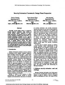
CPU. The ISS model without timing information can provide acceptable simulation speed, but the system accelerator hardware requires having certain acceptable timing information for performance evaluation. Figure 1 depicts the system with an ISS CPU model and cycle accurate hardware IPs. However, such an architecture that is built within an ESL development environment may suffer from poor simulation performance when application and operating system are also simulated. For this reason, a new simulation system that replaces the host CPU is necessary, and using a virtual machine is a preferable choice. In the development of a system accelerator, a full system environment is preferred, such as Simics [6], M5 [7], or QEMU [8]. Figure 1. Different simulation models in one platform
A full system simulation platform (including processor cores, peripheral devices, memories, interconnection buses, and network connections) is able to boot and run an unmodified commercial operating system. It can also run realistic workload under a reasonable simulation time. Nevertheless, current support on developing virtual hardware for full system simulation platforms is not as rich as that found in commercial ESL integrated development environment. In this paper, we integrate a virtual machine with an ESL integrated development environment, to provide a fine-grained system-level development and verification framework for highperformance system accelerators. This paper is organized as follows. Section 2 and Section 3 describe the system architecture and framework respectively. Section 4 discusses the implementation issues. Section 5 describes two examples to demonstrate our system. Finally, Section 6 concludes this paper.
2. SYSTEM ARCHITECTURE Figure 2 shows the system architecture of the simulation framework that consists of a virtual machine platform and the intended subsystem accelerator. The host system is modeled with the
165
virtual machine whereas the system accelerator can be developed using the related tools provided by the ESL design kits [4], [5].
3.2 Performance Evaluation
2.1 Host System Virtual Machine - QEMU
A good simulation is a trade-off between its accuracy and its performance, i.e. simulation time. By simulating only the necessary details, we can simulate effectively while still reaching a certain acceptable accuracy. Our main target is to build a system accelerator development environment, so what is required for the host, is an open-source operating system, and a tool-chain to develop the device drivers. Due to this need, we have used an un-timed virtual machine model to provide full system capability and at the same time to accelerate the simulation speed for the host system. To achieve this, we have chosen QEMU as our virtual machine. QEMU is an open source virtual machine, and is used in many projects, such as Google Android [9]. We modify the QEMU source code and build the required hardware as un-timed models. If a timed model is required, a project, called QEMU-SystemC [10][11] can provide us for such a design environment.
Host Applications Operating System Device Driver HOST-SA Interface
HOST-SA Interface
Power I/O Port
I/O PHY
System Accelerator (SA)
ESL Tools (SystemC, C/C++, HDL)
2.2 System Accelerator Hardware Environment
Figure 2. System architecture
Current commercial ESL integrated development environment can be used as a system accelerator development environment. For example, CoWare Platform Architect, SoC Designer, or other ESL development platforms. These ESL development platforms support SystemC and C/C++ modeling tool, and some even support cosimulation between SystemC and Hardware Description Language (HDL). Designers can use all kinds of microprocessor, on-chip-bus, peripherals, and other built-in libraries to build the SoC components in the system accelerator. The behavior model of I/O devices and DRAM can also be developed using SystemC or C/C++. In simulations, the power system is not necessary, but it is possible to include power estimation techniques into ESL models for evaluation. The details of the interactions between a host and a system accelerator will be discussed in the later section of implementation.
Physical Host QEMU 1 Applications
Virtual Host ( OS , Drivers Ξ ) Host-SA Interface
System Accelerator Hardware Design ( Behavior or Cycle Accurate )
3
ESL Tool
To demonstrate full system simulation capability of the proposed framework, we use a practical and simple example to describe the system framework and procedures of execution flow.
According to the top-down concept in ESL design flow, high level model is adopted to implement the entire system in the preliminary stage. Then Golden Test bench is set up for use in the following development and verification stages. As shown in Figure 3, we can build a Virtual Host by QEMU in Physical Host, which runs on the real computer, and a system accelerator hardware development environment in ESL platform, that is connected to the Virtual Host. As the communication mechanism is ready for use, application programs and hardware designs can be developed at the same time as shown in Figure 3 for the execution flow. First, on QEMU the specified application is run to prepare data for the hardware device and then transmit to the hardware device by Virtual Host supports, which include system calls and the driver to access Host-SA Interface device. Behind the hardware process, the response data will be replied to Virtual Host via the HOST-SA Interface and this completes the procedure of an execution flow. By this method, we can develop hardware devices in the ESL platform using a high level model and application on the host, which allows the device drivers and related test bench to be designed and tested at an early stage.
4
2 Host-SA Interface
3. SYSTEM FRAMEWORK
3.1 Procedure of execution flow
DRAM
Hardware Process
Figure 3. Procedure of execution flow With the Golden Test bench, we can use a more accurate model to implement the system accelerator and continue with the top-down design flow on the ESL platform. Specifically, the cycle accurate register transfer level (RTL) design can be used for the accelerator, so we can evaluate the performance of the system accelerator. The only limitation in our platform is that there is no timing information in the host, so it is hard to precisely model the latency taken by the host CPU to run a program. A Host-SA bridge, however, has been implemented in the ESL platform, which can be used to model the bandwidth of the communication channel between the system accelerator and the host. Hence we are still able to estimate the performance of the system accelerator. A possible solution can address to this limitation. We can profile the events between system accelerator and the host, such as an interrupt service routine, in functional verification stage. Then the timestamp is measured by executing these events in real computer or counting its dynamic instruction count. Finally, we can evaluate the performance of the whole system by embedding the timing information into Host-SA bridge module to create appropriate latency.
166
4. IMPLEMENTATION ISSUES 4(08 �&��&��
Figure 4 shows the detailed structure for our implementation that uses CoWare Platform Architect for ESL and/or RTL development.
1
[���&RPSXWHU�6\VWHP�(PXODWRU RU� $50�6\VWHP�(PXODWRU��$50�9HUVDWLOH�EDVHERDUG� 9LUWXDO�+DUGZDUH
4.1 Operating System and Device Driver
4(08�6\VWHP&�:UDSSHU 6RFNHW�,QWHUIDFH
Linux is chosen as our operating system. Since Linux is an open source environment, it has the flexibility for use to make changes on the host operating system environment. For different operating systems and different system accelerators, specific device drivers are required. Common device drivers use either I/O register access or memory access to communicate with the hardware. We have used the specific APIs to provide these accesses, which provide easy modification that can be ported to different system accelerators. We have also provided a standard interrupt service routine, which provides a response to the hardware suitable for our designated interrupt handler.
2
Data
Interrupt Signal 6RFNHW�,QWHUIDFH
4(08�6\VWHP&�:UDSSHU +267�6$ %ULGJH 0
&R:DUH�3$ �&�&���� 6\VWHP&�� +'/
4.2 The Interface between Host and System Accelerator
,QWHUUXSW� &RQWUROOHU
'5$0 6\VWHP&�0RGXOH
6
6
6
2Q�&KLS�%XV���$+%��$;,��3/%��2&3�%XVಹ�
0
6
9LUWXDO�,�2� ,QWHUIDFH
3
To make our system a general environment, that suits most needs, we have upgraded the interface in QEMU-SystemC, including a PCI bus adapter, which can be used in an x86 environment, for studies of desktop systems, and an AHB bridge, which is used in AMBA environment, for studies of embedded systems. The QEMU-SystemC project has provided QEMU a data transfer interface to access data from the SystemC module. However, it has not yet provided a complete communication mechanism for software and hardware. Typical communication mechanisms for software and hardware are polling, interrupt, or a combination of both, and require both software and hardware support. The Linux device driver model has provided software support, like polling APIs and interrupt service routine, and the system accelerator in the ESL environment requires hardware support. Since polling in implementation is just reading the memory, it requires no extra hardware support. For interrupt, an interrupt controller is required. Therefore, an interrupt controller is implemented along with the system accelerator, and an interrupt line is connected from the system accelerator to the internal interrupt handler in QEMU. In this way, the system accelerator is able to send interrupts to the host QEMU, and ask the interrupt service routine in device driver to respond to this event. In certain applications, such as network offload engine, which needs to transfer a large amount of data to the host system, interrupt is a barrier to high speed transfer. Therefore, an interface that accesses host memory from the system accelerator is used to improve speed. Due to this reason, we have designed a local master interface in HOST-SA Bridge module, to satisfy such needs. In a system accelerator, many kinds of interfaces can be adopted to connect the HOST-SA Bridge module and Interrupt Controller module with different on-chip-bus. In order to set up an AMBAbased system, we use the API of CoWare AHB TLM to attach these modules to the AHB bus. In addition, Open Core Protocol (OCP) [12] can also be used to carry out a more flexible interface that is compatible with other types of ESL platforms.
4.3 Communication Mechanism The communication mechanism between QEMU and SystemC can be classified as either working in a distributed system or in a single computer. For a distributed system, network sockets can be used to communicate between processes in different computers. In this way, the system can be expanded easily, but requires higher overheads for each communication. For a single computer, kernel process communication mechanisms, such as shared memory, can be
167
0
6
3$&
�'63
...
9LUWXDO�,�2�%HKDYLRUDO�0RGXOH �&�&����6\VWHP&
3K\VLFDO�,�2�,QWHUIDFH
Figure 4. Detailed implementation used. In this way, the system has lower communication overheads, but is less scalable. Both of the versions have been developed, and can be applied to different use of environments.
4.4 Virtual Input/Output Interface The virtual I/O interface function provides us a verification interface to connect to either a virtual behavior module, or a physical I/O module. For network issues, it allows designers to connect to the real world computer through network, or a virtual network test bench. For graphic issues, it allows designers to connect to a virtual or physical monitor. To connect to the physical environment on the network, we have used Raw Socket [13], a library, to send a self made MAC frame or IP datagram to the real world network interface card and bypass the normal TCP/IP flow in the operating system. The network offload engine can also receive the MAC frames directly from the network interface card. This provides a channel for the HBA to communicate with a real computer using MAC frames and interact with the outside world. The advantage of the virtual network is that we can simulate a 10Gbps or even 100Gbps network, and measure the system performance without acquiring a real network interface card.
5. PLATFORM DEMONSTRATION We have made one example platform to verify our framework design as shown in Figure 5. First, we implemented a simulation platform with a PAC DSP [14] instruction set simulator model to verify the accuracy of the interface between the host and system accelerator in our framework, including data transfer and interrupt mechanism. We developed two multimedia applications, including Fast Fourier Transform (FFT) and H.264 Decoder, and utilized the PAC DSP to assist the computation. We use the H.264 decoder application as an example, and the detailed steps are as follows: (1) H.264 decoder application is executed to process precalculated data and to prepare routines for PAC DSP.
Physical Host QEMU
FFT
H.264 Virtual Host ( Debian Linux ) Socket Interface
Socket Interface
PAC DSP Platform ( Instruction Set Simulator Model )
CoWare PA
Figure 5. Framework demonstration for PAC DSP (2) When the driver of PAC DSP is invoked, the data and routines are transferred from QEMU to the internal memory of PAC DSP platform through QEMU-SystemC interface. (3) The driver of the upper layer commands the PAC DSP hardware module in CoWare PA to decode the data basing on the decoding routine. (4) The PAC DSP hardware module informs the upper-layer QEMU of the completion of the H.264 decoder routine through interrupt. (5) At last, QEMU retrieves the interrupt signal from PAC DSP and then dumps result images.
performance system accelerator designs. We also showed a case study in order to demonstrate the usage of this framework. Designers can rapidly develop the subsystem hardware or IPs in the ESL environment and related software, including device drivers in the virtual machine for full-system hardware-software co-simulation. This paper focuses on DSP co-simulation; however, our framework can also be used for other specific system accelerators or IPs in embedded systems.
ACKNOWLEDGMENT This work was supported in part by the Industrial Technology Research Institute (ITRI) and the National Science Council, Taiwan, under Grant NSC 96-2221-E-006-192-MY3.
Our design framework focuses on full system simulation, including an OS, so using a fast virtual machine instead of a processor core in CoWare PA is a more suitable method. Table 1 shows the simulation time between a CoWare PA only platform, which has no OS, and a QEMU-based CoWare PA platform, which runs an OS.
REFERENCES [1]
Table 1. Simulation time of various ESL platforms CoWare PA only
CoWare PA + QEMU
[2] [3]
FFT
7.7 sec
6.3 sec
[4]
H.264
60 sec/frame
121 sec/frame
[5] [6]
In Table 1, the simulation time of the FFT application is almost the same for the two systems while for the H.264 application, the QEMU-based system takes much longer time. This is due to the significant host and DSP communication of the H.264 program. Since our communication mechanism uses network sockets, it is flexible but may incur high simulation overheads should heavy host and DSP communication occur. The H.264 application has much more data passing than FFT and this causes the obvious difference in simulation time. To overcome this disadvantage, other low overhead but less flexible inter-process communication method, like shared memory, can be explored to improve this framework.
[7]
[8] [9] [10] [11]
6. CONCLUSIONS
[12] [13]
In this paper, we have enhanced the work of QEMU-SystemC, including an enhancement between host and system accelerator communications, a fast transfer support, and a connection to physical world. Through this work, we have developed a framework that provides a full system simulation ESL environment for high-
[14]
168
B. Bailey, G. Martin, and A. Piziali, “ESL Design and Verification: A Prescription for Electronic System Level Methodology,” Morgan Kaufmann/Elsevier, 2007. Open SystemC Initiative (OSCI), http://www.systemc.org/. D. Gajski and L. Cai, “Transaction Level Modeling: An Overview,” HW/SW Co-Design Conference (CODES), 2003. CoWare Platform Architect, http://www.coware.com/products/platformarchitect.php. SoC Designer, http://carbondesignsystems.com/. P. S. Magnusson, M. Christensson, J. Eskilson, D. Forsgren, G. Hallberg, J. Hogberg, F. Larsson, A. Moestedt, and B. Werner, “Simics: A Full System Simulation Platform,” IEEE Computer, vol. 35, Iss. 2, pp. 50-58, Feb. 2002. N. L. Binkert, R. G. Dreslinski, L. R. Hsu, K. T. Lim, A. G. Saidi, and S. K. Reinhardt, “The M5 Simulator: Modeling Networked Systems,” IEEE Micro, vol. 26, Iss. 4, pp. 52-60, Jul.-Aug. 2006. QEMU, http://www.nongnu.org/qemu. Android - An Open Handset Alliance Project, http://code.google.com/android/. QEMU-SystemC, GreenSocs, http://www.greensocs.com/en/projects/QEMUSystemC. M. Marius, P. Antoni, M. Marc, M. Borja, and C. Jordi, “Mixed SW/SystemC SoC Emulation Framework,” IEEE Int’l Symp. on Industrial Electronics, 2007. OCP International Partnership, http://www.ocpip.org/. A brief programming tutorial in C for raw sockets, http://mixter.void.ru/rawip.html. PAC DSP, http://www.itri.org.tw/