58
J. LETTL, S. FLÍGL, ELECTROMAGNETIC COMPATIBILITY OF MATRIX CONVERTER SYSTEM
Electromagnetic Compatibility of Matrix Converter System Jiří LETTL, Stanislav FLÍGL Dept. of Electric Drives and Traction, Czech Technical University, Technická 2, 166 27 Prague 6, Czech Republic
[email protected],
[email protected] Abstract. The presented paper deals with matrix converters pulse width modulation strategies design with emphasis on the electromagnetic compatibility. Matrix converters provide an all-silicon solution to the problem of converting AC power from one frequency to another, offering almost all the features required of an ideal static frequency changer. They possess many advantages compared to the conventional voltage or current source inverters. A matrix converter does not require energy storage components as a bulky capacitor or an inductance in the DC-link, and enables the bi-directional power flow between the power supply and load. The most of the contemporary modulation strategies are able to provide practically sinusoidal waveforms of the input and output currents with negligible low order harmonics, and to control the input displacement factor. The perspective
source
filter
of matrix converters regarding EMC in comparison with other types of converters is brightly evident because it is no need to use any equipment for power factor correction and current and voltage harmonics reduction. Such converter with proper control is properly compatible both with the supply mains and with the supplied load. A special digital control system was developed for the realized experimental test bed which makes it possible to achieve greater throughput of the digital control system and its variability.
Keywords Matrix converter, electromagnetic compatibility, pulse width modulation strategy, control system.
bidirectional switch matrix uR
load
SAR
SAS
SAT
iA
SBR
SBS
SBT
iB
mains
LF
CF
uS
uT
IM SCR
SCS
SCT
iC
VPK00071
clamp circuit
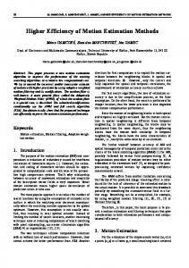
Fig. 1. Basic power circuit of the realized three-phase to three-phase matrix converter system.
RADIOENGINEERING, VOL. 15, NO. 4, DECEMBER 2006
59
1. Introduction
P
Until now the topic of matrix converters has attracted mainly academic attention, with investigation in this field begun in the seventies. The very first attempts to establish the matrix converter technology was presented by Gyugyi and Pelly [1]. A significant contribution was given in the late seventies by Venturini who published a paper presenting the topology and some functional control algorithms. At the time of Venturini’s first publication, the proposed control algorithms allowed a voltage transfer ratio of 50 % only. The input current quality was better than for traditional drives, but still the input power factor was low. In the eighties an improved control strategy was proposed [2]. The voltage transfer ratio was now raised to 87 %, which was proven to be the theoretical maximum without overmodulation. The input current quality was also improved. In the late eighties space vector modulation schemes were introduced by different authors [3], [4]. Especially Hubert and Borojevic were very active in this field. The space vector modulation of the matrix converter offers the full theoretical voltage transfer ratio and sinusoidal input current with an adjustable phase angle. Most papers about matrix converters deal with modulation strategies and control algorithms. Only a few treat the hardware required for the matrix converter. However a technological background is necessary for test bed implementation and in a much larger amount to become mature for industry production. Especially the design of the input filter is a rarely seen topic. A novel enterprise was the introduction of experimental integrated IGBT module by Eupec some years ago [5].
SR
R
SA
A
SS
S
B ST
T
SB
C SC
N
Fig. 3. Indirect frequency convertersimplified instantaneous switch state schema.
derived from the given switch states sequence of the twelve switchers of the indirect frequency converter (see Fig. 2. and Fig. 3.). The matrix converter instantaneous switch state matrix S can be afterwards determined by means of the instantaneous switch state vectors sABC and sRST as follows
S=s
T ABC RST
s
⎛ SA ⎞ ⎜ ⎟ = ⎜ S B ⎟(S R ⎜S ⎟ ⎝ C⎠
SS
⎛ S AR ⎜ ST ) = ⎜ S BR ⎜S ⎝ CR
S AS S BS SCS
S AT ⎞ ⎟ S BT ⎟ SCT ⎟⎠
3. Realized Matrix Converter System In order to prove the matrix converter theory and to prepare a working matrix converter system for experiments [6], [7], a development of the following components has been undertaken: • simulation program • virtual Target PC simulation • control hardware
2. Matrix Converter Control Design
• system software
Great number of sophisticated strategies of pulse width modulation methods, and control algorithms for induction motor control in terms of various optimization criteria are known in case of indirect frequency converters, whereas both the inverter and the rectifier can be operated with pulse width modulation. The instantaneous state of both the output and the input converter waveforms depend at any time on the switch state of the converter power switches S. Suitable switch states sequence of the nine matrix converter switches can be indirectly
• monitoring software
P SPR
SPS
SPT
SAP
SBP
SCP
R
A
S
B
T
C SNR
SNS
SNT
SAN
SBN
Fig. 2. Indirect frequency converter instantaneous switch state.
power
SCN
N
switches
• power parts • modulation and control algorithms From a practical point of view this was done by programming in MatLab / Simulink / Plecs, C, C++, Java, Assembler and VHDL as well, followed by the design of printed circuit boards, soldering and wiring. Together it can be evaluated as about 10,000 lines of source code accompanied with the design of PCBs. In Fig. 4 the relations among realized software and hardware components are depicted in the form of a workflow diagram. First, the algorithms can be tested in a simplified way, defined in graphical form usually as in Simulink. In this step no special commutation patterns are realized, and an infinitely quick switching is assumed. In the second step, the algorithms are rewritten in the programming language C and compiled in MatLab. For this purpose, a model of the real switching unit is implemented in MatLab as well. At this point the algo-
60
J. LETTL, S. FLÍGL, ELECTROMAGNETIC COMPATIBILITY OF MATRIX CONVERTER SYSTEM
rithm should already include a commutation method (see Fig. 5.). Then, in the third step, the algorithm can be recompiled with libraries written for the target system and copied there. In the fourth step, the program is already running in the target system. Monitoring software has been developed for its control by a host computer.
G+S
C+S
(Host PC) is equipped with any multitasking operating system as is usual nowadays. It serves for compilation of the target real-time applications and for monitoring purposes only. The latter PC is equipped with a multi I/O PCI card Meilhaus ME-2600i containing 16 A/D and 4 D/A converters and a 32 bit bidirectional digital I/O port. This card is connected with an external rack that deals first of all with signal adjusting, pulse generation, and error signal management.
Host PC
Host
LPT
COM
(monitor program)
Target PC
Target
(RT OS, ADC & DAC)
VPK00120
Control rack
Fig. 4. Work flow proposal for realized software and hardware.
(interface cards)
3.1 Basic Simulation of the System
Virtual Target PC
Plecs
control_algorithm.c
Simulink Matlab Operational System VPK00121
Fig. 5. Virtual Target PC software structure.
3.2 Control Hardware The employed control system is based on two common personal computers (see Fig. 6.). The first one
generator (energy spliter)
~ ~
A combination of MatLab, Simulink and the toolbox Plecs has been chosen for the realization of basic models of the matrix converter system. PLECS (Piecewise Linear Electrical Circuit Simulation) is a toolbox for the fast simulation of electrical circuits within the Simulink environment. It is specially designed for power electronics systems. The model of the whole power part, including mains, input filter, switch matrix, and the load circuit, has been assembled in the Plecs environment from its library components. The control circuit and the modulator unit generating switching pulses have been implemented directly in Simulink. All the algorithms are defined in a graphical form. Tables of switching combinations are described in m-files.
traction motor
Fig. 6. Realized configuration of matrix converter control system.
A special unit has been developed for the generation of switching pulses. It is connected to the digital output from the I/O card. A kind of 24 bit parallel bus is implemented, which enables the connection of two switching units. Some of the signals are used for control and synchronization purposes, 12 signals define desired states of the output bits (switch word bus) and 12 the relative times corresponding to particular switching words. It is possible to define up to 16 switch events on average for every period. The switching unit has to be able to generate exact switching patterns and to be programmed for the next regulation cycle simultaneously. This is done with a help of the dual port memory which is implemented in the FPGA which is employed in the switching unit (see Fig. 7.). The controller of the switching unit assures that programmed switching events are saved one after the next to the correct positions in the dual port RAM. In this way a FIFO structure with flexible length is actually created. The value of the last not yet used time part of the programmed event is continuously compared with
RADIOENGINEERING, VOL. 15, NO. 4, DECEMBER 2006
the value of the internal timer which is reset at the beginning of every regulation period and when they match, the switching words are applied to drivers of the optical outputs of the switching unit. Two pieces of these switching units are employed in the matrix converter version of the control system. E-TIM-STANv5 20MHz
FPGA
The power part of the realized matrix converter includes the input filter, the semiconductor devices on the heat sink, the switching logic, the protection, the circuit breakers, and the current and voltage sensors. The proposed rated power is about 12 kW.
controller
32 x 24 bit dual port RAM
ters in the target system even while the target system is running in real time operational mode. It is also possible to download the saved waveforms. The main disadvantage of this implementation is the limitation of data transfer speed caused by communication between the monitoring program and MatLab. Thus, a version running outside of MatLab was also successfully tested.
3.5 Power Part
12 bit counter
12
61
digital bus
Fig. 7. Switching unit.
3.3 System Software The realized system software serves to shield the user from the PC and I/O card hardware. This is done by exact determination of the place where the user should write his algorithms and by defining variables that serve as gates between application and system software. The kernel of the system software serves for synchronization of the control loop with an externally generated synchronizing signal, which is connected with one of the special purpose inputs of the I/O card. The frequency of the synchronization signal can be adjusted in the control rack. According to this signal the kernel repeatedly starts particular system processes (data conversion, communication with the monitoring software, keyboard service routine, etc.) as well as the actual control algorithm. According to the results of the measurement, the user application can undertake any necessary counting and fills to the table of switching events for the regulation period. These tables are then again used by the system software as input data for routines programming the switching units. The remaining time is used for communication with the host system.
3.4 Monitoring Software The monitoring program consists of the set of mutually communicating programs programmed in the MatLab, JAVA, and C languages. However, from the user’s perspective it seems to be only one application. The monitoring software enables changing the parame-
The input filter consists of three coils and star-connected capacitors. The cut-off frequency can be adjusted by selecting of the number of capacitors used and / or by selecting a branch outlet of the inductor in the range from about 1 up to 4 kHz. The bidirectional switches are constructed from two anti-serial connected IGBTs in the common collector configuration. The transistors are split into six groups according to their emitter potential and into two groups according to whether they are connected to the input or output side of the converter. The first three of the row of transistors connected to the output are connected with their emitters to the output phase A, the second group to the output phase B, etc. In the middle of the heat sink six diode modules (each made up of two diodes) have been placed in order to assemble the capacitor based clamp circuit.
Fig. 8. The driver unit for three transistors at the same collector voltage potential.
For each group of three transistors one driver unit is used. It has an optical interface (three inputs for switching pulses, one input for an enabling signal and finally one output for an error signal). The error signals are collected in the control rack and in the case of any error pulses are disabled on all units. The most recent version of the driver unit can be seen in Fig. 8.
62
J. LETTL, S. FLÍGL, ELECTROMAGNETIC COMPATIBILITY OF MATRIX CONVERTER SYSTEM
3.6 Control Method Implementation The realized converter is connected with an induction motor, which is one part of a machine set. The set consists of the 0.75 kW / 380 V induction motor, the 5 kW / 220 V DC machine and the small DC machine excited by permanent magnets, which is used for speed measurements. In order to be able to test the implemented modulation methods a simple control loop for the asynchronous as well as the DC machine has been implemented. The output frequency of the matrix converter is regulated during transient processes on the basis of measured speed so that the rotor slip frequency remains constant. Since the employed motor is of very small rated power, the control based on this modest slip adjustment is completely sufficient for modulation algorithm testing. The limitation of the slip frequency, as well as other parameters can be changed during operation with the help of realized monitoring software. The employed modulation approach is based on indirect space vector modulation, since it guarantees according to the modulations carried out the lowest harmonic distortion of the input current. It is obvious that in the implemented system special current-polarity or voltage-polarity sensing circuits are not employed. However, for assembling correct switching patterns this information is necessary. But, the volt-
age waveforms are measured by the system, since information about size and position of input voltage space vectors are fundamental for modulation routines. The rotation of the input voltage vector is observed and its value is predicted for the next step. This is then used for estimation of line-voltage polarities and i.e. for the fourstep commutation method. As far as the DC machine is concerned a simple current regulator has been implemented. The employed chopper also has an optical interface and thus it can be easily controlled from the same switching units as those used for the matrix converter. After counting all switching events for both converters, the switch events are sorted according to their time components.
4. Obtained Results The proper function of the matrix converter control system is illustrated by the matrix converter input and output voltage and current waveforms and their harmonics shown in Figures 9, 10, 11, 12. In this case the matrix converter is fed from the symmetrical three phase source of 50 Hz, linked to the symmetrical load (the power circuit is connected in accordance with Fig. 1), and controlled by means of the above mentioned indirect pulse width modulation method at the matrix converter IGBT´s switching frequency of 2 kHz.
Fig. 9. Typical output voltage and current waveforms harmonic analysis for indirect space vector modulation at 20Hz.
RADIOENGINEERING, VOL. 15, NO. 4, DECEMBER 2006
Fig. 10. Matrix converter input voltage and current waveforms.
Fig. 11. Matrix converter output voltage and current waveforms for 20 Hz.
Fig. 12. Matrix converter output voltage and current waveforms for 80 Hz.
63
64
J. LETTL, S. FLÍGL, ELECTROMAGNETIC COMPATIBILITY OF MATRIX CONVERTER SYSTEM
5. Conclusions
Acknowledgements
The developed matrix converter control hardware and software system makes it possible to achieve greater throughput of the digital control system and its variability. The results obtained on the built-up experimental test bed have proved proper function of the designed conception of the matrix converter control system and high level of the matrix converter energy conversion electromagnetic compatibility as concerns both the currents and voltages harmonic content (see Fig. 9, 10, 11, and 12) and the input phase displacement (see Fig. 10). It is evident that the developed special digital control system ensures the proper compatibility of the matrix converters both with the supply mains and with the supplied load. In comparison with other types of power converters the high-level EMC of the realized matrix converter control system is brightly evident because it is no need to use any complex equipment for power factor correction and current and voltage harmonics reduction.
The research described in the paper was financially supported by the research program MSM 6840770017.
References [1] GYUGYI, L., PELLY, B. R. Static Power Frequency Changers. New York: Wiley, 1976. [2] ALESINA, A., VENTURINI, M. Analysis and design of optimum amplitude nine-switch AC-AC converters. IEEE Transactions on Power Electronics, 1989, vol. 4, no. 1, pp. 101-112. [3] WEICHMANN, E. P., ESPINOZA, J. R., SALAZAR, L. D., RODRIGUEZ, J. R. A direct frequency converter controlled by space vectors. In Proceedings of PESC. 1993, pp. 314-320. [4] HUBER, L., BOROJEVIC, D. Space vector modulation for forced commutated cycloconverters. In Proceedings of PESC. 1989, pp. 871-876. [5] HORNKAMP, M., LODDENKOETTER, M., MÜNZER, M., SIMON, O., BRUCKMAN, M. First IGBT module for matrix converter. Power Electronics Europe, 2001, issue 4. [6] LETTL, J., FLÍGL, S. Matrix converter in hybrid drives. In Proceedings of Problems of Present-day Electrotechnics Conference. Kyiv (Ukraine), 2004, vol. 3, pp. 77-80. [7] LETTL, J., FLÍGL, S. Matrix converter control system. In Proceedings of Progress in Electromagnetics Research Symposium. Hangzhou, 2005, pp. 395-398.
About Authors… Jiří LETTL was born in Beroun, Czech Republic, 1952. He received his Ph.D. degree from the Czech Technical University in Prague in 1980 and became assistant professor in 1993. He was employed by the Czechoslovak Academy of Sciences in Prague, by DANFOSS Vienna, and by many other industrial companies as a manager. Since 2002 he works at the Czech Technical University in Prague as the head of the Department of Electric Drives and Traction. His research covers optimalization of electromechanical conversion of energy parameters in electric drives and power electronics systems, design and realization of advanced control algorithms of AC drives and sophisticated PWM strategies of various semiconductor power converters (such as rectifiers, frequency converters, matrix converters, etc.), electromagnetic compatibility of semiconductor power electronics systems. Stanislav FLÍGL was born in Prague, Czech Republic, 1974. He received his Ph.D. degree from the Czech Technical University in Prague in 2005. In 1999 he spent as a trainee six months on “Institut für elektrische Maschinen und Antriebe” of the University Hannover. In 2001 he obtained the “DAAD” scholarschip and spent two years on “Lehrstuhl für Erzeugung und Anwendung elektrische Energie” of the University Bochum. Since 2004 he is employed as a research worker by the company ŠKODA ELECTRIC Ltd. He deals with the control hardware and software development for electric drives and traction vehicles. He is interested in the direct frequency control, signal processors, systems based on PC for power converters control, and JAVA language.