for all blocks of a Matlab/Simulink simulation, which .... blocks within the Matlab/Simulink environment. ... that executes the loop body of a block multiple times.
Fully Automatic Worst-Case Execution Time Analysis for Matlab/Simulink Models ∗† Raimund Kirner‡, Roland Lang§, Gerald Freiberger§, and Peter Puschner‡ {raimund,peter}@vmars.tuwien.ac.at Abstract In today’s technical world (e.g., in the automotive industry), more and more purely mechanical components get replaced by electro-mechanical ones. Thus the size and complexity of embedded systems steadily increases. To cope with this development, comfortable software engineering tools are being developed that allow a more functionality-oriented development of applications. This paper demonstrates how worst-case execution time (WCET) analysis is integrated into such a high-level application design and simulation tool – Matlab/Simulink – thus providing a higher-level interface to WCET analysis. The Matlab/Simulink extensions compute and display worst-case timing data for all blocks of a Matlab/Simulink simulation, which gives the developer of an application valuable feedback about the correct timing of the application being developed. The solution facilitates a fully-automated WCET analysis, i.e., in contrast to existing approaches the programmer does not have to provide path information.
1
Introduction
As a consequence of technological advances, more and more mechanical systems are getting replaced by electro-mechanical ones (see, e.g., the growing number of embedded-system components in today’s automobiles, aircraft and trains). To deal with the demands of the future design and development of embedded realtime software, functional modeling of applications and automatic code-generation will be used instead of tradi∗ This work has been supported by the IST research project “Systems Engineering for Time-Triggered Architectures (SETTA)” under contract IST-10043. † Matlab and Simulink are registered trademarks of the Mathworks, Inc. ‡ Vienna University of Technology, Austria § Dependable Computer Systems OEG, Vienna, Austria
tional hand coding. To deal with high safety demands, time triggered operating systems (OS) and communication systems are used. The latter require pre-runtime information about scheduling and communication patterns, and task execution times. Matlab/Simulink is a widely used software tool for designing and simulating models of control applications. To build up and simulate real-time applications it is required to know the timing behaviour of the system. Having tight WCET values of code components is mandatory to enable a timely correct system simulation. Various research and development work has come up with solutions for representing entire realtime systems with Matlab/Simulink models. Using Matlab/Simulink has the advantage that it generates so-called executable specifications for the analysis of applications at a high level of abstraction and provides automatic code generation to reduce development costs and coding errors. In order to evaluate the timing of Matlab/Simulink models and to make sure that models meet their timing requirements, we have developed an approach for the WCET analysis of Matlab/Simulink models [5]. This approach has been implemented in a prototype WCET tool. The contribution of this method is that it works fully automated, i.e., the user does not have to bother with annotations for path information. Instead, the required control-flow information is automatically derived by the code generator from the Matlab/Simulink model. As a consequence, modeling and simulating an application within Matlab/Simulink can be done “as usual”; the user gets WCET analysis “for free”. It is the purpose of this paper to describe this solution to the WCET analysis of Matlab/Simulink models. Although the actual WCET analysis of programs is typically performed on the assembly or object-code representation of these programs, high-level programming languages are the more adequate and preferred interface of WCET analysis to the user [10]. A number of languages have been extended with WCET anno-
of annotated C code by the “Model Management and Simulation” module. The “WCET Analysis” module is self-contained and operates autonomously. For reasons of transparency towards the user, however, the user interaction with the “WCET Analysis” module is performed via the “Model Management and Simulation” module. The results of the WCET analysis are propagated back to Model Management in the form of WCET back-annotation data. The WCET analysis process is directly coupled with code generation.
tations (Euclid [8], Modula2 [13], ADA [1], C [4, 9], etc.). An example for WCET analysis of programs at a more abstract level than “standard” programming languages can be found in [2] for the Statemate Statechart system [3]. This paper presents our WCET analysis approach that has been integrated into the Matlab/Simulink environment. The paper is structured as follows: Section 2 gives an overview of the main components of the WCET analysis tool chain. The possible paradigms used to model tasks are given in Section 3. Section 4 describes the code generation from a simulation model. The concept of the WCET analysis tool is given in Section 5. Section 6 describes how the results from WCET analysis are integrated into Matlab/Simulink. The multiple insights into WCET analysis results are listed in Section 7. Finally, Section 8 presents conclusions.
2
one-time by Engineer: WCET Analysis Handling
by Matlab/Simulink user: Matlab/Simulink Model
wcetC Target Files
WCET Analysis Framework
As described in [6], the main components of the WCET analysis framework shown in Figure 1 are:
Target Language Compiler Matlab/Simulink
Executeable WCET Analysis Results
Figure 2. Engineering Process To integrate WCET analysis into Matlab/Simulink we modified the tool chain of Matlab/Simulink. The engineering process is shown in Figure 2. All modifications of the Matlab/Simulink block-set that are necessary to generate WCET analysable code are done only once by the developer of the framework. This includes the software extensions that integrate the WCET analysis into the Matlab/Simulink tool chain. The user of this framework can therefore model applications inside Matlab/Simulink as usual and calculate the WCET with no extra effort.
Figure 1. Main Modules of Framework
Model Management and Simulation: contains the modeling of tasks, providing a user interface for WCET information and code generation. It is responsible for obtaining all data relevant for the simulation model from the user and maintains this data for further processing. In addition, this module provides model simulation to allow, for example, designing controllers for open or closed-loop control. The module further provides code generation, to produce executable algorithms of the designed and analyzed controllers. The simulation environment used is Matlab/Simulink with several extensions as described in this paper.
Figure 3. Model Management and Simulation
WCET Analysis: calculates the WCET of an executable algorithm that is provided in the form
The simulation of applications in Matlab/Simulink is not necessarily done in real time. The WCET anal2
ysis itself is performed for the target hardware chosen by the user. The subcomponents of the “Model Management and Simulation” module are shown in Figure 3. The subcomponents “Target Code Generation”, “Matlab/Simulink Model” and “Back Transformation Tool” are described in more detail in Sections 3, 4 and 6 respectively. The module “WCET Analysis” is described in Section 5.
3
3.2 The Sample-Time/Offset Approach This approach is based on Simulink’s simulation paradigm where each block has a sample-time and an offset where both are multiples of the base sample rate of the entire model. During code generation, all blocks in the model that are on the same sample-time and offset are placed into one task function in the source code. The task table of the OS is derived from the so-formed tasks.
Modeling in Matlab/Simulink
4
One of the major issues in creating a functional model of a time-triggered real-time system is to represent OS primitives like tasks and inter-process communication in the functional model. For the simulation of the components of a time-triggered OS, its functional model requires information about the worst-case execution time of each task. With this information, e.g., statements about the occurrence of preemption of time-triggered tasks can be made at simulation time. Figure 4 shows the principle components for modeling tasks. For modeling of time-triggered tasks there are in general two different possible approaches.
Generating Code
It is in general not possible to derive WCET bounds for task models in Simulink without knowledge of the stages hidden behind the user interface, e.g., model code generation and compiler stages. To assess execution times, we must also take optimization techniques in all these stages into consideration. It is therefore necessary that source code in a high-level programming language is generated from the Simulink model. This code generation depends on the task-modeling paradigm used, as described above. On the other hand, the generated source code must comply with the syntax and semantics of the WCET-analysis compliant source code, that is wcetC in our implementation. The code generation for our simulation tool chain uses the Target Language Compiler (TLC) of the Real-Time Workshop (RTW), which is an extension to Matlab/Simulink for rapid prototyping, realtime simulation or stand-alone simulation. The Matlab/Simulink environment was extended to provide and manipulate custom WCET annotations for the blocks of an application. In addition, the blocks have been extended to store the results of the WCET analysis. For the target code generation stage, the TLC was adapted to generate annotated C code (written in wcetC, see Section 5.1). The modifications and extensions of the Matlab/Simulink environment that are required to integrate WCET analysis can be summarised as follows:
3.1 The Triggered-Subsystems Approach In this approach Simulink subsystems with a trigger input are used to model tasks. All Simulink blocks that are contained in these triggered subsystems and in subordinate subsystems are part of the task’s functional model. An OS-block that is placed outside the task blocks is used to generate signals that trigger the task activations. These trigger signals are generated according to a task table that describes the activation intervals and offsets of tasks. During code generation, each of the triggered subsystems becomes a task function in the source code. The task table of the OS is derived from the OS-block’s configuration data.
• Provision of custom WCET annotations for all blocks within the Matlab/Simulink environment. • Design of a verification tool to verify the custom WCET block annotations prior to the code generation stage. Figure 4. Modeling Tasks in Matlab/Simulink
• Modification of the configuration files for the TLC to account for the block annotations and to produce correctly annotated C code. 3
• Design of an appropriate back-transformation tool to reintegrate the WCET results into the Matlab/Simulink model and display WCET information to the user.
%function Outputs(block, system) Output WCET_BLOCK_START(”BlockPathName”,-1);
[...statements..]
4.1 Reproduction of WCET at Block Level
WCET_BLOCK_STOP(”BlockPathName”);
%endfunction Figure 5. Sample adapted Output Function
For model optimization by the user it may be necessary to know the WCET of the source code that each particular block and subsystem in the Simulink model produces. If this information is needed, the source code generator of our tool set produces block start and stop markers that mark the source code that is produced from each block. In order to generate code, each block has its own code generation functions that are called by the code generator. In general, a Matlab/Simulink block translates into static and dynamic code. The static part initialises variables and data structures whereas the dynamic part represents the block’s algorithm. Depending on the complexity of the block’s algorithm, the block has one or more functions for code generation (e.g., the Integrator block uses one code generation function for the code that calculates the derivatives, one code generation function that updates its state, and one code generation function that updates the output). Each of these functions must be provided with dedicated start and stop markers to be emitted together with the generated code. The start marker is added at the beginning of a code generation function, the stop marker at its end. The start and stop markers of a block are parameterised with a unique identifier that allows to identify all code that has been generated from a particular block. This makes it possible to assign the correct WCET for each Matlab/Simulink block once the WCET has been computed. This identifier is constructed from the name and the full path of each block inside the model in order to guarantee uniqueness. The assembling of the full block file path name is done automatically by the code generator. The above described adaption of the code generation was applied on each Matlab/Simulink block. The skeleton of an adjusted code generation function is depicted in Figure 5. The start and stop markers are shown in bold style. Optimization features of the code generator that produce overlapping blocks or block ranges could lead to unexpected WCET results for each block since fractions of the code are shared between them. We have chosen the approach to assign in this case to each overlapping block the whole execution time of its code.
4.2 Source Code Annotation To facilitate a high-quality WCET analysis, the code generator annotates the generated code with path information, e.g., loop bounds, (i.e., upper bounds on the number of iterations for each loop). Note that this path information is derived automatically from the model blocks. The software developer is thus completely freed from the burden of analyzing the behaviour of the code and coding path annotations. 4.2.1
Adding Upper Loop Bounds
When loop control code is generated, the statements of the loop body are said to be rolled, i.e., a loop body is said to be rolled when it is placed within loop control statements (in contrast to expanding it by duplicating the code). The TLC code generator uses two types of loop rolling mechanisms to produce loop constructs. They are realized either by the %for directive or by the %roll directive. Both directives contain conditional statements that define whether the loop should be rolled or the code of the loop body should be duplicated instead. The %roll directive can be used in a more flexible way than the %for directive and is the preferred construct of the RTW. The following subsections address how these constructs are adjusted to add the WCET path annotations in the loop header of the produced loop. Extension to the %for Directive The %for directive is used by the TLC to generate code that executes the loop body of a block multiple times. Multiple execution can be achieved by duplicating the code of the body or by generating loop control code around the code. The body is rolled (code for a loop is generated) only when the second argument of the %for directive evaluates to true during code generation. The third argument of this directive is an assignment, that is only performed when the loop is rolled. Otherwise the left side gets assigned the null-string. This mechanism 4
is used to generate different code inside the body depending on whether the loop has to be rolled or not. The first parameter of the %for directive is an assignment with the constant loop execution number. This number is used for the loop exit test. After extending this directive by editing the code template files of the corresponding blocks to support WCET analysis, this number is also used to annotate the loop bound. Figure 6 shows an example usage of the %for directive (code template for a certain block, used by the TLC). The additional annotation for WCET analysis is shown in bold style. %for {
ident1 = exp1,
exp2,
In contrast to the %for directive, the definition of the output code fragment for the %roll directive is given by four template functions: 1. RollHeader: This function is called once on the first usage of the vector that will actually roll. 2. LoopHeader: This function is called once for each section that will roll prior to the body of the %roll statement. It is used for the %roll directive to output the loop header. The value for parameterising the WCET annotation is given by its parameter %. The adapted version of this function is shown in Figure 8. The added WCET loop annotation is depicted in bold style.
ident2 = exp3
3. LoopTrailer: This function is called once for each section that will roll after the body of the %roll statement.
int i; for (i=0; i < %; i++) WCET_LOOP_BOUND( % )
{ %body Output[i] = Input[i]; %endbody }
4. RollTrailer: This function is called once at the end of the %roll statement if any of the ranges has caused loop rolling. Whenever the TLC code generator determines that a given block will roll, it performs calls to the above functions to output the specific pieces of the loop control statements.
} %endfor Figure 6. Annotated %for Directive As a result of this extension, every loop code produced by the %for directive can be bounded to the given maximum iteration count.
%function LoopHeader(block, StartIdx, Niterations, Nrolled) Output %assign lcv = "i"
Extension to the %roll Directive
for ( % = %; % < %; % ++ )
%roll is the directive that is most often used for performing loop rolling. The general usage of this directive is shown in Figure 7. %roll allows to specify whether a statement should be rolled into a loop or not. This can be specified in a more flexible way than by the %for directive. roll-vector-exp is a vector of intervals for the loop index. Whenever one of these intervals is greater than the threshold given by the second argument threshold-exp, code for a loop is generated (the execution for this interval has been rolled). Otherwise the statements in the body are duplicated multiple times.
WCET_LOOP_BOUND( % )
{ %endfunction Figure 8. Annotated LoopHeader Function
4.3 Code Generation Example This subsection presents a loop rolling example using the %roll directive and the Constant standard Matlab/Simulink block. The Constant block generates a specified value independent of time. The value is given by the Constant value block parameter. The output can be scalar or a vector, depending on the size of the given Constant value parameter. In the current example the Constant value parameter is set to [int16(1), int16(2), int16(3)]. This means that
%roll ident1 = roll-vector-exp, ident2 = threshold-exp, block-exp [...statements...] %endroll Figure 7. %roll Directive 5
the block produces a 3-dimensional integer vector signal consisting of the elements 1, 2, and 3. The task of the Constant block is to provide the specified parameter values as a signal on its output. At the generated code level this means that the block has to copy the appropriate values from its parameter structure area to its output structure area while a simulation step is performed. To copy the parameter values from one structure to the other structure, the Constant block uses a C for loop instruction. The required C statements of the for loop are produced using the %roll loop rolling mechanism. Values for loop iteration bounds are automatically computed during the code generation. The roll regions vector roll-vecotr-exp in the example Constant block is [0:2] since there are exactly three parameter elements (1, 2, and 3).
block. This technique is useful for using already (by calculation or measurement) analyzed libraries.
5
WCET Analysis Tool
The task of the “WCET Analysis” module is to derive the WCET of the annotated C code and to provide a correlating assembly output that can be executed on the target hardware. In order to derive safe upper bounds, the WCET analysis method is based on “Static Execution Time Analysis”. The theoretical concepts of this approach are described in [11, 12]. The WCET analysis is performed by gathering timing information at a high representation level of the application (simulation model) and performing WCET analysis at assembly-language level. This allows the generation of the timing information automatically by the TLC of the model management module (see Section 4 for further details) when emitting the program code for the model. The annotated C code acting as a high-level programming interface is derived from ANSI C. Besides the standard C statements it has several extensions to express information about the control flow inside the source file. This language is called wcetC (see Section 5.1).
WCET_BLOCK_START(”/Constant”, -1);
{ int_T i; for (i=0; i < 3; i++) WCET_LOOP_BOUND ( 3 )
{ y0[i] = p_Constant_Value[i]; } } WCET_BLOCK_STOP(”/Constant”);
&(')'+*+,.-/,10�24365736*�2)0
8:9@?)A+BDC1EGF�FIH/J.?+JLK H�F4MN?+J1?
�������� �
� ������������� �����"��!#��!%� $ �
Figure 9. Produced Code of the Adapted Constant Block
The produced code of the Constant block has the appearance as depicted in Figure 9. The produced loop passes the values from the parameter structures referenced by p_Constant_Value[i] to the outputs structure referenced by y0[i]. The produced loop is bound by a corresponding WCET annotation. In addition the start and stop markers denoting the block’s code are shown.
O6PQPQR�S�T)U VXW6Y�Z)R
Figure 10. WCET Analysis Tools The WCET analysis tools process the annotated C code and produce a result file containing the calculated WCET values and an assembly file that can be processed by an assembler to generate a corresponding executable. As depicted in Figure 10, the schematic structure of the WCET analysis tools consists of two main components:
4.4 Block Library Analysis To be able to integrate blocks that generate library calls that have already been analyzed into the source code, the tool reuses the information it has already calculated; the tool avoids any attempts to re-calculate the WCET for such a call. Therefore the source code of each block is annotated with a “preliminary WCET value”. A value of ’−1’ forces the WCET analysis tool to calculate the WCET for the block. A non-negative integer value causes the block not to be evaluated. Instead the given value is returned as the WCET for the
Compiler: The compiler is derived from the GNU GCC1 . It uses a modified front-end to parse and translate ANSI C code with WCET annotations. Low-level WCET tool: This tool computes the WCET bounds. The computed WCET information is propagated back to the “Model Management and Simulation” module. 1 GCC
6
. . . GNU Compiler Collection
In the following the functionality provided by the compiler and the low-level WCET tool are described in more detail.
5.2 Transformation of Program Code A program written in wcetC is parsed by the modified compiler. This compiler not only transforms the code, but also translates the control-flow information that is required to perform precise WCET analysis at assembly/object level [7] during its operation. The compiler is based on the GNU C-compiler GCC. The grammar of the compiler has been extended to accept the WCET annotations for the programming language and to transform them correctly down to the assembly code generation phase. This transformation is also able to deal with compiler optimisations.
5.1 Annotated Source Language The interface between the Simulink environment and the WCET analysis is defined by wcetC [4], which is derived from ANSI C. As a central feature, wcetC has extensions to specify control flow information inside the source code. The following constructs [11] have been added to the syntax of ANSI C to support static WCET analysis: Loop Bound: Loop bounds describe the maximum iteration count of a loop construct.
5.3 Analyzing the Assembly Code Besides the object modules for rapid prototyping the compiler generates assembly-code annotated for WCET analysis. The WCET analysis tool is directly called by the compiler. It processes the assembly-code files that have been produced by the compiler. The output format of the WCET analysis tool supports backannotation to assembly and wcetC code. It also provides a special format for Matlab/Simulink. A more detailed description of the back-annotation formats is given in Section 7. Well-known techniques can be used to calculate the WCET. We use integer linear programming (ILP) to simplify the method required for searching the program flow path through the structure tree of a program. The WCET calculation is performed directly on the solution of the ILP problem [12]. The tool currently supports the C167 and MC68k processors from Infineon and Motorola respectively. These processors are used by our industrial project partners. The C167 contains features like a 4stage pipeline and a jump-cache. These features are modeled in the WCET analysis tool by extending the generated ILP problem, to guarantee safe results with low overestimation.
Scope: A scope is a local environment for expressing possible program execution paths. Marker: Markers are used to label a certain position of a program. Restriction: Restrictions in the form of equations and inequalities are placed at the end of a scope to describe the control flow of the code inside the scope. These equations and inequalities are used to build the restrictions for a linear programming problem [12], on which this WCET analysis method is based. Triangular loops (as for example in FFT2 ) are typical applications of restrictions. Beside the integrated annotations for describing (in)feasible program execution paths there are additional annotations to identify the Matlab/Simulink blocks from which the code has been generated: Block Info: These annotations provide a reference from code fractions to the corresponding Simulink blocks. This enables the identification of execution times at single block level in the simulation model.
6
Build Info: This information is used for code revision tracking. It is generated by the simulation tool and passed through the whole analysis environment. It is not required for the WCET analysis itself.
The WCET analysis tool processes the Matlabgenerated source code and produces several files with WCET back annotations. The most important files for this design process are the block wcet files and the task wcet files. The block wcet files contain a list of entries, where each entry consists of the block name and the corresponding WCET value. The task wcet files contain overall WCET values for their task functions.
A comprehensive description of wcetC is given in [4]. 2 FFT. . . Fast
Back-Annotation
Fourier Transformation
7
WCET information. The block interface displays a list of all tasks with their related WCET information. This information consists of the sum of the subordinate block WCET on the one hand, and the total task WCET on the other hand.
6.1 Concept of the Back Annotation Process In order to visualize the computed WCET information, the WCET information located in the block wcet files and task wcet files is mapped back to the Matlab/Simulink model. This is done by a socalled S-Function in Simulink. The S-Function reads the information from the WCET result files and annotates the model by resolving the block-name-to-WCET relationship. A recursive process calculates the WCET of each subsystem by adding the WCET values of its subordinate blocks and subsystems. The resulting WCET values are then displayed both for each block and each subsystem (see Figure 11).
6.2.2
Back-Annotation for the Triggered- Subsystems Approach
The “triggered-subsystems task modeling approach” allows for displaying the WCET information in the same way as described for the “sample-time/offset approach” in Section 6.2.1. In addition, it provides the information needed to represent the WCET value for each task function inside the task subsystem of the Simulink model. A custom Simulink block inside each task subsystem is used to display task-related WCETs. We call these blocks “WCET Info” blocks, see Figure 11.
6.3 Back-Annotation of OS Information Based on the knowledge of the task activation times on a time-triggered operating system and the calculated WCET bounds the framework can detect and handle the occurrence of task overlappings. Figure 11. Back-annotated Subsystem
7 6.2 Back-Annotation of Tasks
Representation of WCET results
The technical process for the back-annotation of WCET results into the Matlab/Simulink simulation model is described in Section 6. For a better insight into the calculated WCET results that relate to the code, the framework also allows to view the back-annotated results at different representation levels. An overview of the different representation levels of the WCET is given in Figure 12. It is possible to view the WCET results for single lines of the generated source code or each instruction of the underlying assembly code. The format of these backannotations is described in the following.
The approach of adding up WCETs of all subordinate blocks is not applicable for tasks. The code generator generates a different wcetC-function in the source code for each task. This function contains not only the block code that lies between block start and stop markers, it also contains local variable declarations and initializations for the block code. Besides the block WCETs these local variable declarations and initializations also have to be considered when calculating a WCET bound for the whole task function. Therefore the WCET analysis tool produces a WCET value for the entire task function.
7.1 WCET results in Matlab/Simulink 6.2.1
Back-Annotation for the Sample-Time/ Offset Approach
The natural way to view the WCET results is presented inside the window of the simulation model. The WCET is shown for the whole model as well as for each block of the system, subsystem, etc. The WCET value of each block is displayed below the name of the block, see Figure 13.
Using the “sample-time/offset task modeling approach”, the WCET values for each task function in the Simulink model is represented using a custom Simulink block in the main system model. This block, called “Task WCET Info Block”, stores all the necessary 8
Figure 13. WCET results in Matlab/Simulink
3. The resulting WCET for this source line. It is the sum of the WCETs of the assembly statements that have been generated from this line.
Matlab/Simulink Model
Target Language Compiler
Experiments have shown that more detailed backannotations of the source do not help to improve the intuitive understanding of the instruction timing.
wcetC Program
wcetC Compiler
WCET
7.3 WCET Results in Assembly Code
Machine Pode + Path Info
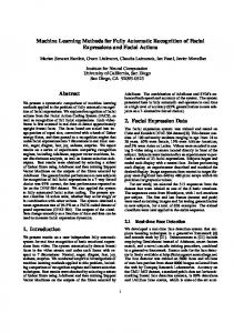
If it is required to explain the WCET at a rather small granularity, it is also possible to view the backannotation at assembly code level. A fragment of the assembly code generated from the above Matlab/Simulink simulation model is shown in Figure 14. The first lines show information about the target hardware of the WCET analysis. In this case it is the Siemens C167 where all the settings for memory locations and external bus timings are summarised. The line called “Build Information:” is used to keep track of version management. The following lines contain the code which is separated into individual basic blocks. For each instruction the execution count and the instruction cycle time is shown for sequential and, if appropriate, also for branching control flow.
WCET Analyzer
Processors Timing Model
Figure 12. Back-Annotation of WCET Results
7.2 WCET Results in wcetC The code generator TLC is well suited for rapid prototyping. The generated C code can also be used as a base for further optimisations or adaptations at source code level. Therefore the WCET analysis framework also supports back-annotation for the wcetC code. The first line of the back-annotation contains the WCET result for the whole function. For each original line containing a source statement, three text columns are added on the left side of the result file. Their meaning is as follows:
8
Summary and Conclusion
This work describes a concept for the integration of WCET analysis into Matlab/Simulink. This is relevant since the usage of Matlab/Simulink is gaining increasing importance in the embedded computing domain. A description about task modelling in Matlab/Simulink has been given. For this modeling, two different approaches were presented – the
1. The line number in the original source code 2. The count of the assembly statements that are generated by the C compiler for the current source line. Obviously this information depends on the compiler optimisations used during compilation. 9
References
/* /* /* /* /* /* /* /* /* /* /* /*
cpu-type: c167 (Format: none) */ Current Configuration: */ EXEC_LOCATION = EXT */ READ_LOCATION = EXT */ WRITE_LOCATION = EXT */ BTYP = 1 */ MCTC = 0 */ MTTC = 0 */ ALECTL = 1 */ MODEL_JUMP_CACHE = true */ USE_DELTA_JUMP_CACHE = false */ Build Information: "Implementation of integer: compiled on: Tue Sep 25 19:04:19 2001" */ /* BLOCK[3,T_ZERO] */ _integer_step: /* NOTE_WCET_TIME(10480) */ /* BLOCK Summary: 1/X [0/0] (0 0/0 0) */ /* BLOCK[26,T_COND] */ movb rl5,#0x0 /* 40(1) [integer.c:68]OTHER */ movb rl4,[r1+#-9] /* 140(1) [integer.c:68]MOV_1 */ cmpb rl4,#0 /* 40(1) [integer.c:68]OTHER */ jmpr cc_EQ,L11 /* 40(1)/60(0) [integer.c:68]CACHEABLE */ /* BLOCK Summary: 1/0 [260/280] (0 0/0 0) */
[1] G. Bernat, A. Burns, and A. Wellings. Portable WorstCase Execution Time Analysis using Java Byte Code. In Proceedings of the 6th International EUROMICRO conference on Real-Time Systems, Stockholm, June 2000. [2] E. Erpenbach and P. Altenbernd. Worst-Case Execution Times and Schedulability Analysis of Statecharts Models. In Proceedings of the 11th Euromicro Conference on Real Time Systems, York, June 1999. [3] D. Harel and A. Naamad. The STATEMATE Semantics of Statecharts. ACM Transactions on Software Engineering and Methodology (TOSEM), 5(4), October 1996. [4] R. Kirner. The programming language wcetc. Research Report 2/2002, Technische Universit¨ at Wien, Institut f¨ ur Technische Informatik, Treitlstr. 1-3/1821, 1040 Vienna, Austria, 2002. [5] R. Kirner, R. Lang, and P. Puschner. Wcet analysis for systems modelled in matlab/simulink. In Proceedings of the 22nd IEEE Real-Time Systems Symposium, Work in Progress Session, pages 33–36. University of York, Department of Computer Science, Report YCS 337 (2001), December 2001. [6] R. Kirner, R. Lang, P. Puschner, and C. Temple. Integrating WCET Analysis into a Matlab/Simulink Simulation Model. In Proceedings of the 16th IFAC Workshop on Distributed Computer Control Systems, Sydney, Australia, November 2000. School of Computer Science and Engineering, UNSW. [7] R. Kirner and P. Puschner. Transformation of path information for wcet analysis during compilation. In Proceedings of the 13th Euromicro Conference on RealTime Systems, pages 29–36, Delft, The Netherlands, June 2001. Technical University of Delft, IEEE. [8] E. Klingerman and A. Stoyenko. Real-Time Euclid: A Language for Reliable Real-Time Systems. IEEE Transactions on Software Engineering, 12(9):941–989, September 1986. [9] C. Y. Park. Predicting Program Execution Times by Analyzing Static and Dynamic Program Paths. RealTime Systems, 5(1):31–62, 1993. [10] P. Puschner and A. Burns. A Review of Worst-Case Execution-Time Analysis. Journal of Real-Time Systems, 18(2/3):115–128, May 2000. [11] P. Puschner and C. Koza. Calculating the Maximum Execution Time of Real-Time Programs. The Journal of Real-Time Systems, 1:159–176, 1989. [12] P. Puschner and A. V. Schedl. Computing Maximum Task Execution Times – A Graph-Based Approach. The Journal of Real-Time Systems, 13:67–91, 1997. [13] A. Vrchoticky. Compilation Support for Fine-Grained Execution Time Analysis. In Proceedings of the ACM SIGPLAN Workshop on Language, Compiler and Tool Support for Real-Time Systems, Orlando FL, June 1994.
Figure 14. WCET Results in Assembly Code “triggered-subsystems” and the “sample-time/offset” approach. The automatic code generation process has been adapted to support WCET analysis. The novelty of this approach is that it facilitates fully automatic WCET analysis. This takes the burden from programmer to write control flow information manually to the code. The required control flow information is directly generated from the Matlab/Simulink model. The WCET analysis is done by transforming the program and its control flow information (which is generated automatically from within Matlab/Simulink) to several representation levels down to the assembly/object code, where the WCET calculation itself is done. Applying a fully automatic WCET analysis in the simulation environment avoids the potential errorprone task of specifying the control flow information manually for generated program code. The user models and simulates applications within Matlab/Simulink as usual and gets, beside the prototype implementation, the calculated WCET values for single components and the whole applications “for free”.
10