AbstractâThe Function-Behavior-Structure model (FBS) of design conceptualizes .... signals and triggers the ringer of the telephone to create (3) the sounds that ...
(IJACSA) International Journal of Advanced Computer Science and Applications, Vol. 7, No. 7, 2016
Function-Behavior-Structure Model of Design: An Alternative Approach Sabah Al-Fedaghi Computer Engineering Department Kuwait University Kuwait
Abstract—The Function-Behavior-Structure model (FBS) of design conceptualizes objects in terms of function, behavior, and structure. It has been widely utilized as a foundation for modelling the design process that transforms posited functions to a description of behaviors. Nevertheless, the FBS model is still regarded as a subjective and experience-based process and it provides no theory about how a function is transformed into behavior. Research has shown that the critical concepts of function and behavior have many different definitions. This paper suggests a viable alternative and contrasts it with the FBS framework of design using published study cases. The results point to several benefits gained by adopting the proposed method. Keywords—conceptual design; FBS framework; flow-based model; function; behaviour; structure
I.
INTRODUCTION
To develop a science of designing, design research aims at a better understanding of design, the development of tools to aid designers, and the potential automation of some design tasks. “Design exists because the world around us does not suit us, and the goal of designers is to change the world through the creation of artifacts” [1]. In engineering design, the product development process starts with the problem definition and requirements. This is followed by the phase of conceptual design, which focuses on what a design must do to realize the requirements. Conceptual design involves the creation of a design description, which is represented graphically, numerically, or textually [2-3]. “The conceptual design phase is acknowledged as particularly critical. It offers the greatest scope for significant enhancements and decisions made in this phase impact all subsequent design phases” [4]. This phase can be based on the framework called the Function-Behavior-Structure model (FBS). The FBS-based design conceptualizes objects in terms of function, behavior, and structure. It has been widely utilized as a foundation for modelling the design process [1][5-6]. This process refers to transforming posited functions to a description of behaviors [1]. Many studies on function, behavior, and structure concepts have been conducted, resulting in several variants and extensions of the model. The model is still regarded as a problematic approach. It is looked at as “a subjective and experienced-based process” [7] and it provides no theory about how function is transformed
into behavior [1]. Research has shown that the critical concepts of function and behavior have many different definitions [8]. “There are debates on the suitability of these notions to the design model, which have left much confusion” [9]. [Such notions as function, behavior, and structure] have created some confusion about and debates on which one should be the most appropriate one. Naturally, a question one may ask is whether they are actually the same thing but with different names or whether they have different scopes of applications for different design problems. [9] This paper suggests a viable alternative to the FBS model of design in terms of a diagrammatic language that is akin to specifications in software engineering. It then applies this alternative to the concepts of function, behavior, and structure. The two approaches are contrasted using published study cases. The results point to several benefits gained by adopting the proposed diagram representation. For the sake of a self-contained paper, the next section briefly reviews the diagrammatic language that forms the foundation of the theoretical development in this paper. The model has been adapted to several applications [10--15]; however, the example given here is a new contribution. II.
FLOWTHING MODEL
The Flowthing Model (FM) is a language for representing “things that flow,” called flowthings. Flow in FM refers to the exclusive (i.e., being in one and only one) transformation among five states (also called stages): transfer, process, creation, release, and receive, as shown in Fig. 1. A flowthing may be called, simply, a thing. Create
Output
Release
Process
Accept
Input
Arrive
Transfer
Receive
Fig. 1. Flow system
The fundamental elements of FM are as follows: Flowthing: A thing that has the capability of being created, released, transferred, arrived, accepted, and processed while flowing within and between flow systems. In the FBS literature, an object is a thing which is observable by its properties. For example, “a power plant is an object which is observable by its
133 | P a g e www.ijacsa.thesai.org
(IJACSA) International Journal of Advanced Computer Science and Applications, Vol. 7, No. 7, 2016
properties, e.g., generating power.” [9]. In FM, power is a flowthing, as shown in Fig. 2. Suppose that we are interested also in representing the power plant as an existing physical thing that is being inspected. Fig. 3 shows the resulting diagram. Power plant
Power
Create
Release
Transfer
not as a mere relationship between inputs and outputs but rather, in general: it is stream(s) of flows and triggering from source(s) to destination(s) through spheres and sub-spheres. A stream here is analogous to, say, the Nile river as a system that includes countries, districts, cities, dams, delta, etc., through which its water flows as spheres and sub-spheres (counting flow systems). The basin of flows and triggering, including interrelated sub-spheres, is the structure of the system.
Fig. 2. Power is a flowthing in the plant sphere
Physical plant itself
Create
Process: inspect
Power plant Power
Create
Release
Θ2
Crank
Coupler
Slider
Θ1
Transfer
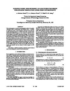
Distance Fig. 4. A crank–slider linkage system (Modified – Re-drawn from [9]
Fig. 3. The plant as an existing thing that is being inspected
A flow system is a system with five stages and connections between them. In FM, flows can be controlled by the progress (sequence) of a stream of events (create, release, transfer, transfer to another sphere, receive, …) or by triggering that initiates a new flow. Spheres and subspheres: These are the environments of the flowthing that reflect structure, e.g., in Fig. 3, the power plant is a sphere with the two sub-spheres (flow systems) power and physical plant itself. Triggering: Triggering in FM is the activation of a flow, denoted by a dashed arrow. It is a dependency among flows and parts of flows. A flow is said to be triggered if it is activated by another flow (e.g., a flow of electricity triggers a flow of heat) or activated by another point in the flow. Triggering can also be used to initiate events, such as starting up a machine (e.g., remote signal to turn on). Example: According to Zhang Lin and Sinha [9], a system is a set of entities connected in a meaningful way. The entities are perceived in the form of their states, which change with respect to time. Fig. 4 shows a crank–slider linkage system where a powered motion is given to the crank and this motion is transferred to the coupler, which, in turn, is transferred to the slider. The angles are state variables. The movement of the slider is called behavior. The behavior of a system is about the response of the system when it receives stimuli. Since the system (structure) is represented by its state, the stimuli and the response are further represented by the state variable. Therefore, the behavior is the relationship between the independent state variable and the dependent state variable… The above definition does imply that the behavior is about the relation between inputs and outputs. [9](Italic added.) Fig. 5 shows the corresponding FM representation. The generation (creation) of a new Θ2 (circle 1) trigger (2) and the creation of a new Θ1 (3), which triggers (4) the creation of a new distance (5). Process in the diagram indicates a possible change in a current value, e.g., rotated angle. Such a diagram provides new meaning for the concept of behavior and structure. We can define the behavior of a system
1
Stimuli
Create
Process: Change
Θ2
2 Coupler Create 3
Crank
Slider
Θ1 Process:
Distance
Change 4
Process: Change
Create 5
Fig. 5. FM representation of the crank–slider linkage system
III.
APPLYING FM TO THE DESIGN PROCESS
This section applies the FM representation to some concepts that are utilized in the context of FBS-based design. A. Functional structuring According to Keuneke [16], functional structuring is useful because, to understand the functioning of a complex system, we often must decompose the system’s function into its components’ functions and decompose each component’s functioning into the functions of subcomponents, and so on. Eventually, this decomposition terminates in behaviors by which these functions are achieved, which point to the functional components used. For example, Fig. 6 shows the functional structuring of a telephone [16]. Transmitter
Condenser microphone Repeating coil
Telephone Receiver Notify
Speaker Ringer
Fig. 6. Functional structural representation of a telephone (re-drawn from [16])
Fig. 7 shows a corresponding FM representation. As seen in the figure, the description is built around flows instead of functions. Due to the importance of identifying these flows in the process of design, we will start by describing these flows shown in the simplified diagram Fig. 8 before explaining Fig. 7.
134 | P a g e www.ijacsa.thesai.org
(IJACSA) International Journal of Advanced Computer Science and Applications, Vol. 7, No. 7, 2016
Fig. 8 reflects the fact that receiving, sending (transmitting in Keuneke’s terminology), and notifying (ringing) are processes (functions) that interweave, and it is difficult to separate them. Both sides of the communication process involved in receiving, sending, and ringing form three steams of flows. Accordingly, the sources and destination of the communication process involves: - The outside caller, named sender (outsider), calls the user of the telephone, named receiver (user), Receiver (outsider) 17
- The telephone user takes the role of dialer, named sender (user), who dials the outsider, named receiver (outsider) In Fig. 7, the communication process starts at circle (1) when the caller, named sender (outsider), send signals by dialing his/her telephone. The telephone receives (2) these signals and triggers the ringer of the telephone to create (3) the sounds that notify the person being called (4), named receiver (user).
9 Sender (outsider) 8
Transfer
Receiver (outsider) 20 7
Transfer
Voice signal Release
Receive Transfer
Transfer
Receive
Transfer
Release
Create
16 Release Transfer
Chassis
Transfer
Release
Create 15
Transfer
14 Transfer
Receive
Transfer
Create 19
1 Sender (outsider)
Receiver 4 (user)
Receive
Handset
Process
Receiver (user) or Sender (user) 13
Release
Dialing signal
Notify Ringer
Receiver (user) 12
10
3
Receive 2
11 Create Voice Create Release
Transfer 18 Lifting up
Create
Receiver (user) 5
Sender (user)
Create
6
Fig. 7. FM representation of the telephone
Accordingly, the receiver (user) (5 – repeated mentioned in several places for simplification of the diagram) performs the lifting up (6) of the handset. These two states together, (a) the ringing (3), and (b) the lifting up (6) of the handset, trigger (7) the transferring (8) of the voice signals coming from the sender (outsider) (9), which flow to the handset (10) where they are converted into a sound (11) that flows to the receiver (user) (12). Now the telephone used plays the role of sender (user) (13) that creates the sound (14) that is converted into signals (15) that flows (16) to the caller in the role of receiver (outsider) (17).
Receiver (outsider) Sender (outsider)
Receiver (outsider)
Voice signal (code)
Chassis Receiver (user) or Sender (user)
Receiver (user) Create
Dialing signal
Notify Ringer Receiver (user) Voice
Sender (outsider)
Handset
As we can see, the conversation now has two sides: - The sender (user) to the receiver (outsider) (circles 13, 14, 15, 16, and 17) - The sender (outsider) to the receiver (user) (circles 8, 9, 10, 11, and 12). It is assumed that the transfer (8) will continue in the permission state after lifting the handset (7). The case of ending the call is not included in this scenario because it is not mentioned in Keuneke’s [16] specification.
Fig. 8. Initial identified flows in the design of the telephone
When the telephone user initiates the call, the process starts at circle 18 where he/she plays the role of sender (user) by lifting up the handset (6) that triggers the dialing signals (19) and a number, which flows to the other telephone of the receiver (outsider) (20). Additionally, the transfer module (8) is set ON in anticipation of signals from the other end, i.e., the sender (outsider) (9). In this case, the same two ways of communicating (circles 8, 9, 10, 11, and 12) and (circles 13, 14, 15, 16, and 17) are open to exchanging the data.
135 | P a g e www.ijacsa.thesai.org
(IJACSA) International Journal of Advanced Computer Science and Applications, Vol. 7, No. 7, 2016
It is clear that if there is any misunderstanding of the telephone functioning process because of the author’s lack of knowledge in telephony, the diagram can easily be corrected. The point is that the diagramming language can express such functionality.
component motivated by cost considerations. In the initial conceptual design, cost is not taken into consideration, thus, it is possible to implement the design of the telephone as four transmission pieces, as in the case of cheap hardware or for the sake of simplicity in production.
Now, we can ask about the functions of Keuneke’s [16] Fig. 6 that are used as the base for building the design of the telephone. The FM representation shows that the functions Transmitter, Receiver, and Notify are interweaved with each other and that it is almost impossible to remove such entanglement. For example, Fig. 9 shows four diverse positions in the FM representation that involve the function of sending. Accordingly, this sharp division of functions seems to be needed at a later stage when our objective is to optimize the four portions of receiving in the FM diagram as one physical
We note that Flows is an alternative phenomenon that provides a base for a pure conceptual design (e.g., optimization of physical implementation is not involved). Over the steams of flows (i.e., flows trigger each other), it is possible to identify the basic structure of the design as shown in Fig. 10. Still, further details can be specified, as given in Fig. 11, where the Transfer module (stage) (circle 8 in Fig. 7) receives signals from Sender (outsider) (9) according to triggering 7 and 20. Fig. 11 also shows a possible pseudo-language level of details for this transfer stage.
Receiver (outsider) 17
Receiver (outsider) 20
9 Sender (outsider) 8
Transfer
7
Transfer
Voice signal Release
Receive Transfer
Transfer
Receive
Transfer
Release
Create
16 Release
Transfer
Release
Create 15
Notify Ringer Receiver 4 (user)
Receiver (user) 12
Transfer
14 Transfer
Receive
Transfer
Create
Dialing signal
19
1 Sender (outsider)
Receive
Handset
Process
Receiver (user) or Sender (user) 13
Release
Transfer
Chassis 10
3
Receive 2
11 Create Voice Create Release
Transfer 18 Lifting up
Create
Receiver (user) 5
Sender (user)
Create
6
Fig. 9. Portions of the FM representation of the telephone that are related to Receive Receiver (outsider) Sender (outsider) Voice signal Receiving Sending Receiving
Notifying Sending
Sending Receiver (user)
Sending Receiving
Sending Dialing signal Sending
Ringer
Chassis Receiver (user) or Sender (user)
Receiver (outsider)
Receiver (user) Receiving Sending
Sender (outsider)
Handset
Sender (outsider) 9 Voice signal (code) 8 Transfer 1- Initially: The module is asleep; 2- If triggering 7 or 20: 2.1 activate flow from 9 2.2- keep active while handset is lifted up (this action is not shown in the diagram)
Receiver 20 (outsider) 7
Chassis
Voice
Fig. 10. Further decomposition of structure of the telephone
Fig. 11. Sample of the possible details of Transfer
136 | P a g e www.ijacsa.thesai.org
(IJACSA) International Journal of Advanced Computer Science and Applications, Vol. 7, No. 7, 2016
of both functions and structures. The abstract embodiment of a structure contains only the relevant information about the structure that is of interest to the designer. The abstract embodiment for the purpose can be expressed in terms of linguistic variables. [17]
B. Behavior and structure According to Khanal [17], referring to his sources, a system can be described using two kinds of abstractions: structural abstraction and behavioral abstraction. In physical models, the structure denotes the arrangement and relationship of components of the physical organization (the visible topology). Alternatively, the structure refers to a structural organization based on functional components [16].
Such sharp distension between structure and behaviors disturbs the Gestaltic depiction where behavior and structure express a holistic representation of the system. In FM, the structure is reflected in terms of spheres while the behavior is represented by the streams of flows. Fig. 13 shows the FM diagram of this cart transmission system. The cart (circle 1) has three spheres: Handle Bar (2), Gearbox (3), and Disc brake (4). However, these sub-systems receive instruction signals from the controller (e.g., driver - 5) who generates three types of signals (6, 7, and 8). Each of the sub-systems; Handle Bar (2), Gearbox (3), and Disc brake (4) embody two flow spheres: instruction signals and the execution of the instruction. For example, the controller generates a braking signal (8) that flows to the disc brake (9) where the signal is received and processed (10) in its flow system (for simplicity’s sake, this has not been drawn in a box). The processing of the braking signal triggers (11) the generation of the brake action (12).
In the structural view, the system consists of sub-systems that interact with each other to achieve functions that can be captured from the behavior view. To avoid complexity, systems are partitioned into minimally interacting sub-systems. Fig. 12 (taken from Eggert [18]) shows the synthesis of a cart transmission system and its functions from a behavioral view (left diagram) and a structural view (right diagram). Transmit engine power (verb)
Steer (verb)
Gearbox (noun)
Handle Bar (noun)
Disc brake (noun)
Brake (verb)
It is clear that flows are important factors in determining the structure of the system. Fig. 14 is an incomplete representation of the structure of the cart transmission system, which can be extracted from the FM representation, as shown in Fig. 13.
Fig. 12. Description by functions (left) and by structure (right) (Re-drawn from [18])
The designer is interested only in dealing with abstractions Controller 5 Steering 7 Create Release
1
Transmitting 6 Transfer
Cart Transfer
Release
Steer Process
Create
HandleBar 2
Transmit Process
Transfer
Create
Process: 10
Release Transfer Breaking 8
Create
Process:
3
Gearbox
Create
Transfer Receive
Transfer
Receive
Receive
11
Process
12
Process
Create
Brake
9 4
Disc brake
Fig. 13. The FM representation of the cart transmission system
Controller
Cart
Transmitting Steer Steering
Signal
HandleBar
Transmit
Signal
Breaking
Signal
Gearbox
Brake
Disc brake
C. Complex systems and purpose According to Hmelo, Holton, and Kolodner [19], understanding complex systems is often difficult because of their multiple perspectives and the fact that their analysis may create conflict beyond the range of everyday experience. Design activities can be an excellent way to help students achieve a more systemic understanding of systems. Hmelo Holton, and Kolodner [19] give a simplified StructureBehavior-Function Model of respiratory systems, which is shown in Fig. 15.
Fig. 14. The structure of the cart transmission system
137 | P a g e www.ijacsa.thesai.org
(IJACSA) International Journal of Advanced Computer Science and Applications, Vol. 7, No. 7, 2016 Structure Lungs Diaphragm
Brain
Behavior Gas passes from high concentration to low across semipermeable membrane. Lower pressure in chest by increasing volume. Send signals to respiratory system. Receive and process signals regarding body status.
intended behavior [20] or purpose [16]. What a function intends to accomplish is achieved by how the behavior is implemented. In general, Kitamura and Mizoguchi [21] define the function of an entity as “a kind of abstraction of changes in objects associated with the entity.”
Function Bring in oxygen for cells, remove waste from cells. Move lungs so they can take in fresh air. Control or regulate movement of lungs in response to changing metabolic needs
In the FM diagram, the purpose can be specified according to corresponding sub-diagrams. Fig. 17 shows the purpose of the lungs in terms of two sub-diagrams: Inhalation of air to extract oxygen that is sent to cells
Fig. 15. A simplified Structure-Behavior-Function Model of the respiratory system (From [19])
Exhalation to remove carbon dioxide from cells
Fig. 16 shows the corresponding FM diagram. First, the body sends signals regarding its status to the brain (circle 1), which are processed (2) to trigger the creation of an instructing signal (3) to the respiratory system (4). The diaphragm receives and processes (5) the brain instruction to either contract or expand (6 and 7, respectively). This causes the physical movements of the inhalation (8) or exhalation (9) of the lungs. The inhalation triggers (10) the pulling in of fresh air, which is processed (11) to generate (12) oxygen that can then flow to the cells (13). On the other hand, an exhalation causes the release (14) of carbon dioxide from the body’s cells.
It should be noted that purpose is a flowthing that can be created, processed, released, transferred, and received. Fig. 18 illustrates purpose as one of the flow systems of the lung. The point of these examples is to show that the notions of function, behavior, and structure can be discussed as features of the FM diagrammatic representation. All are obtained uniformly as global characteristics of the FM diagram in terms of spheres and sub-spheres, flow systems, flows, and triggering. This is in contrast to the FBS model in which doubts are raised about the meaning and suitability of these notions to the design process.
Over the years, there has been a great deal of functional representation research. A function of a system refers to its Brain
4 Respiratory system
Status
Signal
Process
Create
Receive
Receive
Receive
Transfer
Transfer
Transfer
2
6 Create Contract
Process 3
5
8
Inhalation
7 Create Expand
10
Receive
Exhalation 9
Transfer Carbon dioxide
Release
11 Process
Diaphragm 1
12 Oxygen Create
Transfer
Create
Transfer
Fresh Air
Release 14
Create
Lung
Body
13
Cell
Fig. 16. FM representation of the simplified respiratory system
Lung Create
Function: Bring in oxygen for cells, remove waste from cells.
Inhalation of air to Inhalation Receive extract Oxygen thatRelease is Process sent to cells Transfer Fresh Air Transfer
Oxygen Create
Exhalation to Transfer Carbon remove carbon dioxide Exhalation dioxide from Release Create
cells
Cell Fig. 17. The function as a sub-diagram
138 | P a g e www.ijacsa.thesai.org
(IJACSA) International Journal of Advanced Computer Science and Applications, Vol. 7, No. 7, 2016
Create
Purpose
Inhalation of air to extract Oxygen that is sent to cells, and Exhalation to remove carbon dioxide from cells
Create
Transfer
Inhalation
Receive
Lung
Process Fresh Air
Transfer
Oxygen Create Exhalation
Release
Create
Transfer
Carbon dioxide Release
Cell Fig. 18. Purpose is a flowthing that can be created, processed, released, transferred, and received
IV.
[8]
CONCLUSION
The Function-Behavior-Structure model (FBS) of design provides no theory about how a function is transformed into behavior, and research has shown that its critical concepts have many different definitions. This paper suggests an alternative approach in which behavior is associated with streams of the flow of things in the system. Structure emerges as the “territories” of these flows, and function is associated with subdiagrams of the total diagrammatic description. Behavior, structure, and function are all developed around the representation. The proposed conceptualization of design in terms of FM is still exploratory and needs more precise analysis; nevertheless, the approach seems to be promising as a unifying framework for the science of designing. [1] [2] [3] [4] [5] [6]
[7]
REFERENCES J.S. Gero, “Design Prototype: A knowledge representation schema for design,” AI Magazine, vol. 11, no. 4, pp. 26-36, 1990. M.J. French, Conceptual Design for Engineers, 3rd ed., London, United Kingdom: Springer, 1999. W.E. Eder and S. Hosnedl, Design Engineering: A Manual for Enhanced Creativity. Boca Raton: CRC Press, 2008. B. Helms, Object-Oriented Graph Grammars for Computational Design Synthesis, Ph.D. thesis, Technische Universität Müchen, March 2013. J.S. Gero and U. Kannengiesser, “The situated function behaviour structure framework,” Design Studies, vol. 25, no. 4, 373e391, 2004. G. Cascini, G. Fantoni, and F. Montagna, “Situating needs and requirements in the FBS framework,” Design Studies, vol. 34, no. 5, pp. 636-662, 2013. S. Borgo, M. Carrara, P.E. Vermaas, and P. Garbacz, “Behavior of a Technical Artifact: An Ontological Perspective in Engineering, Proceedings of the 2006 conference on Formal Ontology in Information Systems,” Proceedings of the Fourth International Conference (FOIS 2006), pp. 214-225.
[9]
[10]
[11]
[12]
[13]
[14]
[15]
[16] [17]
[18] [19]
[20] [21]
Y. Chen, Z.Q. Lin, P.E. Feng, and Y.B. Xie, “Understanding and representing functions for conceptual design,” Proc. International Conference on Engineering Design, ICED'07/223, Paris, August 2007. W.J. Zhang, Y. Lin, and N. Sinha. “On the function-behavior-structure model for design,’ in Canadian Design Engineering Network Conference 2005, Kananaskis, July 2005. S. Al-Fedaghi, “Awareness of context of privacy,” 7th International Conference on Knowledge Management, Pittsburgh, Pennsylvania, 2223 October 2010. S. Al-Fedaghi and A. Alrashed, “Threat risk modeling,” 2010 International Conference on Communication Software and Networks, Singapore, 26-28 February, 2010. S. Al-Fedaghi, “Privacy as a base for confidentiality,” Fourth Workshop on the Economics of Information Security, Harvard University, Cambridge, MA, 2005. S. Al-Fedaghi, “Scrutinizing the rule: Privacy realization in HIPAA,” International Journal of Healthcare Information Systems and Informatics, vol. 3, No. 2, pp. 32-47, 2008. S. Al-Fedaghi, “Scrutinizing UML activity diagrams,” 17th International Conference on Information Systems Development, Paphos, Cyprus, 2527 August, 2008. S. Al-Fedaghi, “Toward flow-based semantics of activities,” International Journal of Software Engineering and Its Applications, vol. 7, no. 2, pp. 171-182, 2013. A.M. Keuneke, “A device representation: The significance of functional knowledge,” IEEE Expert, vol. 24, pp. 22-25, 1991. Y.P. Khanal, “Object-oriented design methods for humancentered engineering design,” Ph.D. thesis, Mechanical and Materials Engineering, University of Western Ontario, Ontario, Canada, 2010. R.J. Eggert, Engineering Design, Pearson: Prentice Hall, 2005. C.E. Hmelo, D.L. Holton, and J.L. Kolodner. “Designing to learn about complex systems,” Journal of the Learning Sciences, vol. 9, no. 3, pp.247-298, 2000, DOI: 10.1207/S15327809JLS0903_2. M. Lind, “Modeling goals and functions of complex industrial plants,” Applied Artificial Intelligence, vol. 8, pp. 259-283, 1994. Y. Kitamura and R. Mizoguchi, “Meta-functions of artifacts,” Thirteenth International Workshop on Qualitative Reasoning, pp. 136-145, Loch Awe, Scotland, 1999.
139 | P a g e www.ijacsa.thesai.org