so that development costs for variant handling can be kept down. ... Particularly,
the configuration of a .... Door H an dle. Trig ge r R ear. Pa sse nge rs. Door. Inte
rio r. An ten na. Pa ..... order to propagate the variant configuration information to.
Functional Variant Modeling for Adaptable Functional Networks Cem Mengi and Ibrahim Armac¸ Department of Computer Science 3 Software Engineering RWTH Aachen University, 52074 Aachen, Germany {mengi|armac}@i3.informatik.rwth-aachen.de
Abstract The application of functional networks in the automotive industry is still very slowly adopted into their development processes. Reasons for this are manifold. A functional network gets very quickly complex, even for small subsystems. Furthermore, concepts for variability handling are not sufficient for future standards such as AUTOSAR. In this paper we will provide an approach to reduce the size of functional networks by applying abstraction and partitioning. The achieved improvements will be described. In addition we will provide an alternative concept to handle variants in functional networks. The approach is based on extracting variation points from the functional network and modeling them separately. Open problems and future work are discussed at the end.
1
Introduction
Today the automotive industry provides customers a lot of possibilities to individualize their products. They can select from a huge set of optional fittings, e.g., parking assistant, rain sensor, intelligent light system, and/or comfort access system. The possibility to configure individual vehicles leads to the situation that both OEMs (Original Equipment Manufacturers) and suppliers have to capture explicitly potential variation points in their artifacts so that a software product line can be established to overcome the development complexity [6]. For requirements specification this is often done with so called feature models [4], where customer visible variants of the vehicle are captured. After requirements specification, a functional network is established, which consists primarily of interacting functions. Ideally, it should be used as a first concretion of the features and should help the engineer to understand the problem domain in a better way. Variation points in functional networks are captured implicitly by modeling a so called maximal functional network.
The idea is to capture every function of the vehicle, e.g., a sensor, an actuator, a control algorithm etc., and to generate variants by removing specific parts of the functional network. This way of variant handling is possible since the automotive software development process is hardwaredependent. A functional network is designed with detailed technical knowledge, such as the used communication infrastructure and deployment information of the functions. Therefore, deleting parts of a functional network can be regarded equally to deleting ECUs (Electronic Control Units) from the vehicle topology. We will call this kind of functional networks in this paper as technical functional networks. The advantage of such an approach is that it is simple, so that development costs for variant handling can be kept down. Furthermore, virtual prototyping, i.e., behavior simulation on a PC, and rapid prototyping, i.e., real-time simulation on a controller of a rapid prototyping system or on an ECU could be almost directly adopted. This is possible because the functional network specifies the interfaces of the functions along with their communication. By implementing the behavior which is compliant to the defined interfaces a prototyping system can be set up. Nevertheless, there are also some disadvantages. Even a technical functional network brings advantages such as simplicity and prototyping possibilities, its size gets very quickly vast so that it rather complicates the tasks of an engineer instead of supporting him. Furthermore, the automotive industry is currently performing a paradigm-shift from a hardware-driven development process to a function-driven development process, to counteract the ever increasing software complexity. The results of this efforts were specified by the AUTOSAR consortium [1]. Basically, AUTOSAR decouples the infrastructure from application software by introducing an abstraction layer between them. This implies that application software can now be developed independently from the hardware. Therefore, the methodology to capture and generate variants in a maximal functional net-
[MA09] C. Mengi, I. Armac Functional Variant Modeling for Adaptable Functional Networks. In: Proceedings of the third International Workshop on Variability Modelling of Software-Intensive Systems (VaMoS 2009), Seville, Spain, Februar 2009. www.se-rwth.de/publications
work will not be the solution for the near future. The mentioned two problems, i.e., complexity of a technical functional network and insufficient concepts for handling variants, involve that the application of functional networks in the automotive industry is still very slowly adopted into their development processes. In this paper we will introduce an approach to facilitate the extensive use of functional networks by reducing their complexity and providing an alternative concept for variability handling without losing the advantages such as simplicity and prototyping possibilities. The complexity reduction is primarily achieved by applying abstraction and partitioning. Abstraction is applied by identifying functions with similar semantic. This is also done for connections between functions. They are grouped to abstract functions and connections. For partitioning we identify parts of the functional network, i.e., functions and their connections which are used to model a specific characteristic of the system. For variability handling we will use a restricted form of feature models which are tailored for automotive functional networks. We will call them functional variant models. In this way we can extract variants from functional networks and model them separately with functional variant models. The result will be a functional network which is modeled on a logical level (in the following called logical functional network). Particularly, the configuration of a technical functional network from a logical functional network will be possible for utilizing the advantages of virtual and rapid prototyping. This paper is structured as follows. In Section 2 we will describe the problems that we are dealing with in this paper. For this purposes we will introduce an example that is used for the whole paper. With the example we will describe the covered problems, i.e., the size of functional networks and variability handling. In Section 3 we will present our approaches to solve the mentioned problems. In Section 4 we will describe related work and in Section 5 we will discuss open problems and future work. Finally, in Section 6 we will summarize the paper.
2
Problem Description and Challenges
In this section we will describe the covered problems in detail. Therefore we will introduce an example, which will be used for the whole paper. Our department has gained experience on automotive software development processes by collaboration with an OEM in Germany. The example is constructed with that knowledge.
2.1
Example: Vehicle Access System
In our example we consider a vehicle access system for three car models. A vehicle access system is primarily a
Table 1. Three car models and their supported features.
Active Access Passive Access Automatic Door Close Selective Unlock Anti-Theft System Immobilizer Crash Unlock Drive Lock
Model 1 x x
Model 2 x
x x
x
x x
x x
Model 3 x x x x x x x
central locking system with additional features that extends a classical central locking with security and comfort features. In Table 1 we listed the features and marked those that will be supported by the appropriate model. For example, an active access denotes a feature that supports the entry into the car by using the mechanical key or the remote control. In contrast to this, in a passive access a user can enter the vehicle without actively using a key. He only needs to carry the remote control with him which is extended by an identification transmitter so that the vehicle can identify the authorized user. While model 1 and 3 support both features, model 2 only supports the active access. The automatic door close is a feature that closes the door automatically. The user needs only to push the door smoothly into the lock. Then the door will be completely closed by a motor that is installed inside the door. If selective unlock is supported, it is possible to unlock the doors sequentially. For example, if the unlock button of the remote control is pressed once, only the driver’s door will be opened. By pressing the button a second time all other doors will be opened. The anti-theft system and the immobilizer are security features which prevent the unauthorized use of the car. While the anti-theft system blocks the steering wheel, the immobilizer additionally controls the engine and gearbox. Since the immobilizer includes in our example also the blocking of the steering wheel, these two features can only be selected alternatively. Finally, the crash unlock feature unlocks the doors in crash situations, while the drive lock feature locks the doors after achieving a predefined speed. If an OEM specifies the requirements for its vehicle models, commonalities and variability in the sense of the software product line paradigm are determined [6]. This has the advantage that common aspects of an artifact can be used for all models, while only variable aspects, which differentiate the products, have to be treated. Commonalities and variability for requirements specification are typically
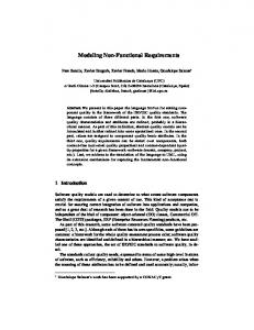
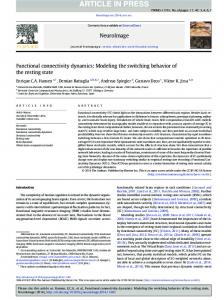
work gets very quickly very complicated, even for such a small example. We did not further modeled the anti-theft system and immobilizer in detail in order to avoid further complexity. It is obvious that a functional network for the whole vehicle is unusable. Reasons for this complexity are multisided. First, the functional network for the vehicle access system presents a maximal model. Therefore, an engineer has to model for example both the anti-theft system and the immobilizer, even they have exclusive characteristics. Second, a system engineer models such a network on a technical level. For example, he has the knowledge about the ECU deployment of the software-based functions with the incoming and outgoing signals. Finally, the network includes redundant functions such as the five drive units with the five lock/unlock signals. For a model with two doors and a tailgate, there is no need for five drive units but rather for three. Further examples are the antennas and sensors. Figure 1. An example for a feature model of the vehicle access system.
captured with feature models. In Figure 1 we designed a feature model for our example. It has mandatory-, optionaland alternative-features, while or-features are not existent. As mentioned before, OEMs currently try to cover the variability problem in functional networks by modeling a maximal technical functional network. This is an approach, which has advantages when it is applied to hardware-driven development processes. If the paradigm shift to a functiondriven approach should be successfully achieved, the modeled functions must be considered on a logical level. Beside of this, it is not always straightforward to build maximal models, since there exist complex dependencies between functions. For example, there are functions with exclusive properties. In Figure 1 this is the case for the anti-theft system and the immobilizer. Furthermore, a function could require another function, so that by building a variant this constraint must be considered. In Figure 2 we have build a maximal functional network for the vehicle access system by using the component diagram of UML (Unified Modeling Language) [2]. Functions are modeled as components and signals are modeled as connectors between ports. Incoming ports are marked white, while outgoing ports are marked black.
2.2
Size of Functional Networks
Figure 2 illustrates a functional network for the vehicle access system. We had defined 8 features, which are concretized in the functional network with about 45 functions and 113 connections. As one can see, the functional net-
2.3
Capturing Variants in Functional Networks
A further important aspect which inhibits the extensive use of functional networks for an automotive system is, that there exist only weak concepts for capturing variants. As described above, OEMs try to build a maximal functional network which is used then to derive the different variants. This results in an enormous size of the modeled functional network (see Figure 2) and therefore inhibits the use by an engineer, because it would take more effort to understand the functional network, instead of helping the engineer in understanding the problem domain. Considering a hardware-driven approach, building maximal functional networks are well applicable. Variants are built mainly by adding or deleting ECUs. Through the ever increasing software complexity OEMs and suppliers were forced to design an alternative approach, which allows decoupling the software from the hardware, so that a more logical view can be established in to the development process. The result of this efforts were specified in the AUTOSAR consortium [1]. Basically, AUTOSAR decouples the infrastructure from application software by introducing an abstraction layer between them. This implies that application software can be developed independently from the hardware. This in turn allows a more logical view on functional networks. Therefore we need an alternative approach to capture variation points, where the technical view on the functional network is completely ignored. Adopting logical functional networks will bring surely a lot of advantages. Nevertheless, a technical functional network such as the one in Figure 2 has also some advantages. Particularly, the functions with their signals can be nearly directly used for virtual and rapid prototyping. To utilize
requestAuthData
id Vehicle Access System
Remote Control
Identification Transmitter
selectiveUnlock
authData
openTailgate
unlock
lock
authData
Exterior Antenna Rear Drivers Side
Mechanical Key
selectiveUnlock
openTailgate
unlock
lock
authData
selectiveUnlock
openTailgate
unlock
lock
authData
Door Handle Trigger Rear Drivers Door
unlock
lock
Door Handle Trigger Drivers Door
Rear Drivers Door Drive Unit
Drivers Door Lock Barrel
Automatic Door Close Drivers Door
Automatic Door Close Rear Drivers Door
doorInLock
Rear Drivers Door Contact
closeDoor
doorInLock
closeDoor
Drivers Door Contact
Drivers Door Drive Unit
Vehicle Speed Sensor
Crash Sensor
Anti-Theft System
unlock
lock
Key Slot
Steering Wheel
requestAuthData
Interior Antenna Luggage Compartment Left
selectiveUnlock
vehicleSpeed
crash
unlocked
locked
doorClosed
doorOpen
unblock
block
blocked
openTailgate
unlock
lock
authData
Exterior Antenna Tailgate
Tailgate Drive Unit
selectiveUnlock
openTailgate
unlock
lock
authData
Interior Antenna Luggage Compartment Center
unlock
unlock
lock
Door Handle Trigger Tailgate
Interior Antenna Luggage Compartment Right
Execute Central Locking
Authentication
disable
lock
Interior Antenna Passenger Compartment Front
Center Lock Button
enable
selectiveUnlock
Evaluate Central Locking
Interior Antenna Passenger Compartment Center
doorInLock
closeDoor
doorInLock
closeDoor
enable
Fuel Filler Flap Drive Unit
Automatic Door Close Rear Passengers Door
Rear Passengers Door Contact
Rear Passenger Door Drive Unit
Automatic Door Close Passengers Door
Passengers Door Contact
Passenger Door Drive Unit
Immobilzer
Door Handle Trigger Rear Passengers Door
Door Handle Trigger Passengers Door
selectiveUnlock
openTailgate
unlock
lock
authData
openTailgate
selectiveUnlock
unlock
lock
authData
Gearbox
Engine
Figure 2. An example for a maximal technical functional network of the vehicle access system.
requestAuthData
requestAuthData
Exterior Antenna Drivers Side
locked
requestAuthData
requestAuthData
Exterior Antenna Rear Passenger Side
Exterior Antenna Passenger Side
this advantage on logical functional networks we must provide an approach to configure logical functional networks to technical functional networks.
3
Functional Variant Modeling for Adaptable Functional Networks
In Section 2 we have described the problems and challenges that we are dealing with. There are mainly two core points that we have analyzed to improve the usability of functional networks in an automotive software development process. First, we have to reduce the size of functional networks to ease the work of a system engineer. He will then be able to use this artifact to understand and describe the problem domain in a better way. Second, variability handling in functional networks requires a new approach to be usable also for new standards such as AUTOSAR. Our approach to reduce the size of a functional network is based primarily on abstraction and partitioning. With abstraction we want to achieve a more logical view on the functional network. This of course will affect the size of the functional network. With partitioning we want to divide the network into parts which belong semantically together. Examples would be an immobilizer, a central locking unit, or, if it would not be too big, even a vehicle access system. With that we want to achieve further reduction of the size. For variability handling we will present an alternative concept for capturing variation points in functional networks. We want to extract variation points from the functional network and model them separately with so called functional variant models. Functional variant models represent a restricted form of feature models and are tailored for automotive functional networks. This approach provides also the possibility to configure technical functional networks for prototyping issues.
3.1
Size of Functional Networks
In Section 2.2 we have analyzed mainly three problems, which influence the size of a functional network. These are the building of a maximal model, modeling with knowledge about technical details, and finally modeling of redundant functions. To overcome these problems we propose to apply abstraction techniques for the last two aspects, and partitioning for the first one. Considering our example in Figure 2 there are some points, where we could apply abstraction. For example, there are four functions to lock or unlock the doors, these are the remote control, identification transmitter, mechanical key, and center lock button. These four functions have all the same tasks, i.e., to control the access into the vehicle. We could replace the four functions by one function which describe exactly the task of the previous functions.
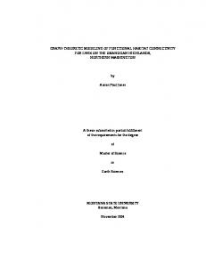
For example, we could add a function called vehicle access controller. Another example is given by the ten functions for the antennas which perform the task of receiving data of the remote control and identification transmitter and to transmit them to an appropriate function. The function for the driver’s door lock barrel performs the same task for the mechanical key. We could replace these functions with one function to model the same task. For example, we could add a function called data transceiver. The five functions for the door handle trigger in Figure 2 could be replaced by one function called door handle trigger. The same technique could be applied to the drive units for the four doors, the tailgate, and the fuel filler flap. This would mean, that we could replace six functions with one function, for example called lock/unlock drive unit. The functions for the door contacts could be reduced in the same manner, i.e., we replace the four functions with one function called for example door contact. Finally, we do not need four functions for the automatic door close, but instead only one function called for example automatic door close. Summarizing the achievements, we see that we can replace 34 functions with 6 functions, which of course reduce the size of the functional network enormously. Note that by reducing the number of functions, we also reduce the number of redundant connections. Another approach to reduce the size of the functional network is to divide the network into semantically equal parts, which we call partitions. For our example in Figure 2 this could be the active/passive access, automatic door close, anti-theft system, and the immobilizer. Note that there must not be necessarily a one-to-one mapping between the features defined in Figure 1 and the partitions. Figure 3 illustrates the result after applying abstraction and partitioning to the vehicle access system in Figure 2. Obviously, the four partitions are now more readable. We have achieved this by modeling semantically equal partitions instead of the maximal functional network for the vehicle access system. Furthermore, we use abstraction as described above, so that the size gets more reduced. Compared to the maximal functional network, which consists of 45 functions and 113 connections, the four partitions totally has 15 functions and 27 connections. Obviously, this is an improvement. In an automotive development process which is adapted to AUTOSAR it would be ideal that such abstraction and partitioning techniques are done when the functional network is designed the first time. In that case the system engineer who has the specialized knowledge should regard such techniques. For the case that a functional network is reused the adaptation must be done by reengineering the network.
Vehicle Access Controller
Lock/Unlock Drive Unit
unblock
locked
id VAS Anti-Theft System
disable
enable
id VAS Active/Passive Access
doorClosed
vehicleSpeed
crash
lock unlock
doorOpen
unlock
lock
authData
block Steering Wheel
lock
unlock
Authentication
Execute Central Locking
Evaluate Central Locking
id VAS Immobilizer
Door Conta ct
disable
Automatic Door Close
closeDoor
(d) Immobilizer
enable
block
(b) Automatic Door Close
Immobilzer
doorInLock
id VAS Automa tic Door Close
Figure 3. Application of abstraction and partitioning to the vehicle access system.
(c) Anti-Theft System
unblock
blocked
Evaluate Central Locking
Authentication
(a) Active/Passive Access
Vehicle Speed Sensor
Crash Sensor
Door Contact
Lock/Unlock Drive Unit
Data Transceiver
Anti-Theft System
unlock
lock
unlock
lock
authData
Gearbox
Engine
Steering Wheel
Lock/Unlock Drive Unit
Figure 4. The structure of a functional variant model.
3.2
Capturing Variants in Functional Networks
In Section 2.3 we have analyzed, that the automotive industry currently performs a paradigm-shift from a hardware-driven approach to a function-driven approach, to overcome the ever increasing software complexity. Particularly, the standardization of AUTOSAR is an important step towards this goal. The standard implies that vehicle functionality can be developed independently from the given infrastructure, which allows a more logical view. Therefore, the approach of modeling a maximal technical functional network to capture variation points will not be the solution for future development methodologies because it has the disadvantage that it becomes very complex and is hardly coupled to the hardware. However, it has the advantage that a technical functional network could be used in a simple way for virtual and rapid prototyping. Adopting a logical functional network involves new requirements for modeling of variants. For example, by abstracting functions we lose information about existing variants. Therefore, we need a concept where we can gain the information back again. Furthermore, it should be possible to generate a technical functional network to utilize prototyping. We propose an approach that is based on the concept of feature models, but is restricted and tailored for variants in logical functional networks. Variants are captured separately with functional variant models. In Figure 4 we have illustrate the structure. Variation points and their variants are modeled in a tree-based structure. The root consists of the modeled partition type and its name. We have defined
Figure 5. An example for a functional variant model for the vehicle access controller function.
four types, namely mandatory, optional, or, and alternative. In this way we can express the characteristic of a partition. For example, in Figure 3(b) the automatic door close partition is an optional partition. On the next level we have defined the variation point that is extracted from the technical functional network. A variation point can be a function or a signal. The next level contains the variant type and its name. Similar to partitions, we also have defined four variant types, namely mandatory, optional, or, and alternative. And finally, on the last level the incoming and outgoing signals are listed. Incoming signals must be denoted with its source and signal name, while outgoing signals must be denoted with its signal name and sink. The source, signal name, and sink can all be variation points. In this way, we can build a hierarchy in our models. Note that a functional variant model never exceed the described four levels and therefore enhances the visibility of variability information. In Figure 5 we have built a functional variant model for the vehicle access controller from Figure 3(a). A vehicle access controller has mandatory functions such as the mechanical key, remote control, and center lock button. These functions are related to the active access feature from Figure 1. Furthermore, the vehicle access controller exhibits an optional function, identification transmitter, which allows the passive access into the vehicle (see Figure 1). Particularly, we have build the premises to generate a technical functional network from the logical functional network from Figure 3(a) together with the functional variant model from Figure 5. By capturing the function and signal information it would be possible, if an configuration framework is established, to regenerate a functional network that
Figure 6. An example for constraints expression between functional variant models. is ready for virtual and rapid prototyping. If we would not model the information in this way, we were not able to distinguish for example between the function mechanical key and the functions remote control, identification transmitter, and center lock button, which all are disabled in a crash situation (see the incoming signals of these functions in Figure 2). Since not all configurations will be valid, we have to introduce a method which allows expressing constraints between functional variant models. An example for this is shown in Figure 6. Only if the identification transmitter is selected, we also have to select all exterior and interior antennas (for the remote control we only need the exterior antenna tailgate). We do not propose a specific constraint language in this paper but rather give a remark that this will also be investigated in future work. The proposed approach allows that the variability information that was loosed when we have applied abstraction and partitioning to reduce the size of a functional network can be gained back again. Particularly, we have the premises to introduce a configuration framework that allows generating a technical functional network for prototyping purposes.
4
Related Work
There exist different techniques to model variability in a software development process. Sinnema and Deelstra give a classification about existing techniques [7]. We have adopted our approach for functional variant models mainly on feature models. In this way it will be easy to synchronize functional variant models with feature models. However, to avoid unnecessary complexity we have adopted our approach to the automotive domain. Von der Beeck describes in his paper [8] an approach
for modeling functional network with UML-RT. In our approach we did not focus on a specific architecture description language, but rather propose a way to reduce complexity and to handle variability. Particularly, we consider thereby the application to new standards such as AUTOSAR [1]. Gr¨onniger et al. propose an approach to model functional networks with SysML to overcome the size and to capture variants [3]. Therefore, they introduce views. A view consists of a specific part of the functional network, such as partitions in our approach. However, in [3] a bottom-up approach is considered, i.e., it is assumed that a complete functional network exists to apply a view on it, while we propose a top-down approach to overcome the complexity in functional networks, i.e., there is no need for a maximal functional network. Furthermore, in [3] variants are also modeled with views. We propose an approach that captures variants separately with functional variant models that allow generating a technical functional network to utilize prototyping. Kaske et al. propose a new approach to use virtual prototyping to validate functional networks [5]. While they focus on how to setup and test functional networks, we deal with the generation of technical functional networks by considering existing variants.
5
Discussion and Future Work
In this section we want to discuss open problems which have to be tackled in future work. The first question that arises is how to integrate feature models from requirements specification with functional variant models. Obviously, there is a strong relationship between these two artifacts. For example, an active access feature from Figure 1 is related to the mechanical key, remote control, and center lock
button functions of the vehicle access controller. One task thereby is to ensure the modification consistency between these two artifacts. Furthermore, a variant configuration must be properly forwarded to the appropriate artifacts and checked if it is correct. For this purposes a framework is needed that controls the consistency and the configuration between these artifacts. In Section 3 we have seen that a functional network is divided into multiple partitions and therefore multiple functional variant models will be necessary to capture the existing variation points. An example is illustrated in Figure 6, where we have the variation points vehicle access controller and data transceiver. Note that these two variation points are included in the same partition, but they could also be modeled in the way, so that they belong to different partitions. The problem still remains the same. The decision about selecting the identification transmitter is related to the decision of selecting the optional exterior and interior antennas. Therefore there is a need to handle the consistency between all functional variant models. A constraint language would be appropriate to specify the constraints. Since we want to generate technical functional networks from logical ones, we also have to give the possibility to relate functional variant models with functional networks in order to propagate the variant configuration information to the functional network. For example, if the functional variant model for the vehicle access controller in Figure 5 could be related to the logical functional network in Figure 3(a), we would have enough information to generate a technical functional network. An obvious question that immediately arises is how this generation would be provided. Particularly, we have to ensure that incoming and outgoing signals are mapped correctly. For example, the mechanical key has no incoming signals compared to the remote control, identification transmitter, and center lock button. If the vehicle access controller is generated to a technical functional network, the signal information must be considered. Furthermore, functions such as the door handle trigger which have no explicit variation point in the logical functional network (compare the Figures 2 and 3(a)), must be completely inserted into the functional network. Another important point which has to be handled is the integration of partitions. If an engineer wants to consider the functional network of two partitions that are related, we must provide a method to join them together. For example, if the active/passive access partition (Figure 3(a)) and the immobilizer partition (Figure 3(d)) should be integrated, the evaluate central locking functions from both partitions must be unified, and that the disable signals must be sent from one port. Finally, tool support for the explained concepts must be provided. Currently, we are considering the problems
on a conceptual level in order to analyze existing problems. Particularly, we believe that there is a need for tools that are tailored for the automotive domain. For example, a graphical functional network editor which only includes necessary concepts enhancing usability would help to support the application of functional networks in the development process. The same is valid for the functional variant model. Nevertheless, we must also consider the concepts on a higher level of abstract to investigate their generalization and compare them with alternatives. In this way we can make statements about the benefits of the proposed approach.
6
Summary
In this paper we have dealt with two problems, namely the complexity and insufficient concepts for variability handling in functional networks. To understand the problems in a better way we have analyzed the current development methodology. It is primarily based on modeling a maximal functional network and building variants by removing specific parts of the network. This process has the disadvantage that it is hardly coupled to the hardware infrastructure and becomes very quickly unclear. To overcome this we have presented an approach to reduce the size of functional networks in order to support the extensive use in automotive software development. For this purpose we have applied abstraction and partitioning. The size reduction provides an improved visibility. Furthermore, the design of a functional network for a system engineer will become more simple, since technical details can be neglected. However, if a technical functional network is reused appropriate adaptations have to be done in order to build a logical functional network. For a completely new designed functional network, the adaptations should be directly regarded. If the mentioned two techniques are applied to reduce the size of the functional network, we lose the implicit variability information. To get the information back, we have proposed the approach of functional variant models. It provides the possibility to extract variation points from the functional network and model them separately in a tree-based structure that is tailored to the automotive domain. Thus, the functional network gets more clear. Moreover, variation points are now explicitly identifiable. In addition, the functional variant model has at most four levels but allows to build hierarchies between functional variant models. It is therefore manageable and allows to integrate a structure into the models. Nevertheless, we have to consider the open problems, such as the integration with feature models, the dependencies between functional variant models, and the generation of a technical functional network from a logical one.
References [1] AUTOSAR Website. http://www.autosar.org. [2] Unified Modeling Language Website. www.uml.org. [3] H. Gr¨onniger, J. Hartmann, H. Krahn, S. Kriebel, L. Rothhardt, and B. Rumpe. Modelling Automotive Function Nets with Views for Features, Variants, and Modes. In 4th European Congress ERTS - Embedded Real Time Software, 2008. [4] K. C. Kang, S. G. Cohen, J. A. Hess, W. E. Novak, and A. S. Peterson. Feature-Oriented Domain Analysis (FODA) Feasibility Study. Technical report, Carnegie-Mellon University Software Engineering Institute, November 1990. [5] A. Kaske, G. Franc¸ois, and M. Maier. Virtual prototyping for validation of functional architectures. In 3rd European Congress ERTS - Embedded Real Time Software, Soci´et´e des Ing´enieurs de l’Automobile (SIA), Toulouse, France, 2006. [6] K. Pohl, G. B¨ockle, and F. J. van der Linden. Software Product Line Engineering : Foundations, Principles and Techniques. Springer, September 2005. [7] M. Sinnema and S. Deelstra. Classifying variability modeling techniques. Information and Software Technology, 49(7):717–739, July 2007. [8] M. von der Beeck. Function Net Modeling with UML-RT: Experiences from an Automotive Project at BMW Group. In N. J. Nunes, B. Selic, A. R. da Silva, and J. A. T. lvarez, editors, UML Satellite Activities, volume 3297 of Lecture Notes in Computer Science, pages 94–104. Springer, 2004.