DESIGN OF A GRIPPING SYSTEM FOR THE AUTOMATED ASSEMBLY OF LARGE BUILDING MODULES Thomas Bock1, Jens Herbst1, Carlos Balaguer2, Mohamed Abderrahim2 1
Lehrstuhl fuer Baurealisierung und Bauinformatik, TU Muenchen, Germany,
[email protected] 2
Departamento de Ingeniería Eléctrica, Electrónica y Automática Universidad Carlos III de Madrid, Spain,
[email protected]
Abstract: A substantial part of automated material handling and assembly is the interface between machine and work piece. These end-effectors may be gripping devices which actually hold the object for moving or placing it within the working range of the machine. But the mere holding of an object while transfering it from one point to another is in most cases not the only function of a gripper. It may also be equipped with sensing capabilities and other features. This paper describes a gripping system for large building components, such as twodimensional panels or slabs and three-dimensional modules. The system comprises the gripping mechanism itself as well as its supporting environment. At first the different functions and the performance of the projected system are investigated and analysed. The second part deals with the design of the gripping system itself. Keywords: gripper, end-effector, prefabricated building elements, sensors, material handling, assembly
1
INTRODUCTION
2
A substantial part of automated material handling is the interface between material handling machine and work piece. The interface (end-effector) is where the machine’s capabilities are utilized. In general end-effectors fall into two different categories: grippers and tools. Grippers are those devices that actually grip an object for moving or placing it within the working range. Using a gripper as end-effector, the path through the machine’s working range is basically a point-to-point process. If the end-effector is not suited to the task, the task cannot be carried out satisfactorily. As construction work consists of various occupational categories it might by necessary to exchange the endeffector by the machine itself in order to execute a different operation. Other end-effector tools are spray guns, hammers, similar to tools used for industrial robots and for prefabrication of building components. End-effectors are usually specifically designed for their task. Because the highest workload of on-site construction consists of handling and assembly operations, the gripper-type end-effector is most interesting in this area.
BASIC GRIPPER MECHANISMS
Grippers can grasp work pieces, center and orientated them, and they include sensors to indicate, if a part is present or not. On the whole a gripper should be as lightweight as possible, for the maximum payload of a machine includes the weight of a work piece. Heavy loads should be held as close to the axis of grip as possible, so as to avoid high moments on the gripper and robot. For costeffectiveness, the gripper should be simple designed and manufactured, easy to maintain, and reliable. Essential gripper action is opening or closing its gripper, both the design of action and the structure of the gripper are very task specific, because products are not always specific. They have got many actions: -
Parallel motion Scissors-like motion One jaw may be fixed, the other moving They can be sprung open or closed
2.1 Classification of grippers For use in the construction sector there are four classes of grippers in use:
104_WA2.doc- 1 –
-
Mechanical clamping Magnetic clamping Vacuum clamping Piercing grippers
Mechanical clamping is the most common mechanism, whereby pneumatic or hydraulic operated devices apply a surface pressure to the component. These grippers are available in different styles: parallel jaws, finger grippers, expansion/contraction grippers, and anthropomorphic hands. Parallel jaws hold a component between flat and/or veered surfaces. These devices can have one or two moving jaws. Finger grippers (parrot beak) either enclose the component, or hold it at the very tip of the jaws. Anthropomorphic hands usually contain three fingers that pick up and maneuver items. This hand could execute work similar to a human hand but it is still in the research phase and probably not suited for on-site application. However this technique can be applied for robot working in the maintenance of buildings and facilities which were designed human-orientated.
forces can lead to damage of materials, so the design of the component and gripper must be checked against this eventuality. Grippers should be fitted with part present sensors which can be mounted on the gripper itself. In the conception phase the gripper, all parts, and tools that the gripper manipulates must be considered. In many cases, whole families of parts must be manipulated by one gripper, so the gripperworkpiece-interface has to be designed accordingly with only slight modifications. The geometry of the component is used to define the operational area which is related to the maximum component dimensions that can be accommodated without affecting the desired performance of the system. -
-
Magnetic clamping uses electromagnetism to hold the component. One particular advantage is that it is component independent. This technique might be used for reinforcement works. The most common style of vacuum grippers is the use of suction cups arranged in a pattern to suit the component, with the vacuum being generated by an ejector or vacuum pump. This technique can be used for ceiling assembly, light interior and exterior wall element assembly, door and window assembly. The piercing gripper punctures the component to lift it. The technique can be used for walls mostly in prefabrication or for insulating roofs on-site and other insulation works. 2.2 Considerations for the design For assembly it is important to consider tolerances by providing the gripper with compliance which will allow inaccuracies in the shape and dimensions of components. Passive compliance means, that the part that is handled moves according to ease the assembly. Active compliance requires a sensor to detect the presence of a constraint. Multiple sensors may be used to detect the forces and torques on the part. This sensory information can be used by the machine controller to determine the best path to follow. During assembly operations a gripper is used to move a component in a three dimensional space. This movement generates dynamic forces at the component-gripper-interface as the gripper accelerates and decelerates during its task. Inertial
The component dimensions are such that the gripper can satisfactorily hold it. The component’s dimensions are such that the component causes no tilting moment, neither on the gripper nor on the components within it. The component dimensions are such that the component can be manoeuvred without collision.
The mounting of the gripper to the machine is an important design factor. In many cases a compliant type gripper is required where the gripper adjusts to tolerances of the parts. Conventional construction cranes have an inherent compliance due to high repeatability. This allows the gripper little freedom and avoids heavy torque loads on the machine. Compliance can be in one, two or all three axis depending upon the requirements of the particular application. Compliance can be accomplished through the use of strings, rubber washers or remote compliant center devices (RCC). The latter are mostly utilized in assembly applications where slight offsets and misalignments are common place. Provided that the object is gripped with sufficient compliance then small lateral misalignment can be corrected by allowing a chamfer to ‘guide’ two objects together. But if tolerances exceed the limits of passive compliance such as a chamfer then the robot systems use active compliance, where sensory feedback is used to reduce lateral and angular errors by physically driving the gripper to produce compensatory motions. The force sensors for such active compliance are usually located in the gripper itself, although some robot designs incorporate them into the joints of the robot, however the speed with which all systems can react is depending on how high a contact force is permissible. Passive compliance using purely mechanical solutions to the problem seems to be practicable for on-site construction since it is more cost effective
and faster if tolerances are within a certain range. Construction robots will not be as stiff as industrial robots, due to the need of lightweight robots for operations in the building on-site. The inherent compliance of a soft construction robot arm might some time solve the problem but such forms of structural compliance are not always suitable. If a building element, e.g. a column, is held ‘loosely’, it will hit the chamfer as it descends, developing a moment which brings the column off angular alignment. As it enters the hole of foundation this will cause jamming (which is retrievable locking by changing the direction of the applied force and moment) or wedging (which is irretrievable locking requiring that the column be pulled out an reinserted). The form of compliance which is in fact required would correct the lateral error. Some designs cannot cope with horizontal angular and simultaneously lateral inaccuracies. For these cases involving purely RCC devices, mechanical multi-axis compliance can be attached to the end of any robot wrist as a platform for the gripper itself. Any angular error sets up a moment which forces one part of the device to rotate without any lateral movement. A separate section of the RCC allows the first section to move laterally independently, without any rotation of the work piece. Practical designs of RCC come in many forms, ranging from devices using sprung levers to those using pneumatic tubing to provide the correct response. Especially useful in assembly, all designs allow the use of minimal forces to achieve close tolerance fits and permit greater variability of parts’ tolerances and cut down machine stoppages due to jamming and wedging. Higher tolerance insertions can be accomplished than a given robot could achieve alone, because lateral errors can be as large as the chamfer used, and even press-fit operations can be managed in which the (deformable) bolt used is actually slightly larger than the hole into which it is forced such as metal bolting of wooden joints. The design of a gripper is crucial for the success of robotic systems. As for industrial robots the gripper costs are between 10 and 20% of the total robot costs. Therefore the following points should be considered before the gripper is designed. -
-
Characteristics of the lightweight arm and the maximum transportable load (i.e. the mass of the gripper plus that of the object to be handled) Characteristics of the object which include: - Weight - Rigidity (e.g. whether - Nature of material
solid or flexible) (e.g. fragility, magnetic properties, finish roughness)
- Geometry,
-
dimensions and structure (e.g. solid or hollow) - Condition (e.g. loading, cutting) - Initial position, orientation, and final position - Contact surfaces (e.g. gripping surfaces, positional stability) - Forces acting on object (e.g. inertia, gravity, pressure) - Environmental conditions (e.g. temperature, humidity, accessibility) Gripper technology Flexibility
The size and function of a gripper is directly related to size, material and weight of the components to be handled. The first parameter that defines the gripper design is static load, which defines the operational capacity in: -
-
-
The component’s weight determines the gripper’s ability to accommodate the component. This reflects the technical limits that have been designed into machine and gripper. The gripper’s ability to restrain the component’s weight by frictional and shear forces determines the weight that can be held without slippage. The orientation of the gripper jaws during a particular manoeuver controls the weight that can be moved. If the jaws are always at right angles to the gravitational force, then the component’s weight is withstood by frictional and/or shear forces; the frictional forces being those that act directly between gripper jaws and the component’s surface.
During automatic assembly the process of joining is very important. First it is to decide whether the joint is movable or fixed. Movable joints allow motion for at least one degree of freedom. Fixed joints do not allow any motion. In construction mostly fixed joints are applied. They have the following functions: -
Move parts in final positions for joining Create forces of joining Block from motions Secure against loosening
One of the most important tasks for grippers on-site is assembling or joining components. Basic functions of joining systems are: Force and moment transmitting, force and moment transferring in and between elements. The following sections describe a gripping system for large building components, such as two dimensional panels or slabs and three dimensional modules. The system comprises the gripping mechanism itself as well as its supporting environment.
Factor
Consideration
object to be handled
weight and size geometrical and physical changes of handled components during construction operation tolerances on the part size surface condition, protection of delicate surfaces actuation method mechanical grasping vacuum cup magnet power and signal pneumatic transmission electrical hydraulic mechanical gripper force weight of the object (mechanical gripper) method of holding (physical construction or friction) coefficient of friction between fingers and object speed and acceleration during motion cycle positioning problems length of fingers inherent accuracy and repeatability of material handling machine tolerances on the part size service conditions number of actuation during lifetime of gripper replaceability of wear components (fingers) Maintenance and serviceability operating environment heat, temperature, dust, ultraviolet light, rays, humidity, moisture, dirt, chemicals water protection plastic shields, use of water-resistant materials air ventilation by fans fabrication materials strength, rigidity, durability fatigue strength, lightweight cost and ease of fabrication compatibility with operating environment interfaces mounting connections and interfacing with machine risk of product design changes and their effect on the gripper design lead time for design and fabrication spare parts, maintenance, service and testing of the gripper on-site during bad weather other considerations use of interchangeable grippers design standards Table 1. Check-list for selection and design of grippers [1]
3
FUNCTIONS OF THE PROJECTED GRIPPING SYSTEM
3.1 Analysis of functions In this section the different functions of the gripping system are analysed. The gripping system is mounted on the material handling machine (e.g. Gantry or tower crane). Its functions include the conversion of mechanical energy into the object’s linear and rotating movement and into gripping forces. In addition different sensors are implemented: -
sensors measuring gripping forces and the existence of the object
-
a system for auto-identification of the building module safety sensors for avoiding obstacles while moving the object
Further features of the system are: an anti-swing unit if the handling machine is cable based a mechanism ensuring safe gripping also in case of loss of power an integrated quality check system including the transmission of information from the building module to the control of the handling machine. This may be information on the integrity of
-
-
connection when the module is assembled at its final position in the building a mechanism to adjust to different shapes of the object (2D / 3D), to different size and weight of the object and to different allocations of connectors mounted on the object a system for the bilateral forwarding of the complex control and sensor data mentioned before
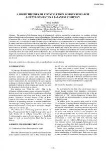
The projected gripping system is designed to lift and move building modules to their final position in the building and to connect them to the foundation or to already assembled modules. As it is to be an (at least semi-) automatic controlled system the basic mechanical properties are extended by sensors and
data transmission. The main components of the complete system (see Figure 1) are the platform, a certain number of grippers mounted on it, the crane control unit and the building component to be handled. The gripping element uses mechanical force for translation and rotation and is equipped with the sensors mentioned above. The sensor information is transmitted to the crane control unit. The control unit collects the information from the sensors, processes them and converts them into control instructions for the gripping system including gripping motion, translation, rotation and − if necessary − also for the purpose of active compliance.
Figure 1. Functions of the gripping system
3.2 Assembly process The on-site assembly process is performed the following way: A prefabricated building element (two-dimensional panel/slab or three-dimensional module) is delivered to the construction site by a truck. It is equipped with connectors for two purposes: On the one hand the connectors ensure automatical placing and fixing of the building element at the final position in the building. On the other hand they serve as fixtures for the material handling machine while transferring the building element on-site. The material handling machine is equipped with a platform like crane supplement which contains several grippers correlatively to the connectors of the module. Using a human-machine-interface the platform is lowered above the module to let the grippers take contact of the connectors. An auto-identification label such as a barcode tag or a transponder ensures the identification by the corresponding identification device mounted on the platform. The identification information is transmitted to the crane control unit, as well as additional information provided by other sensors (position, collision...). Then the building module is lifted and moved towards its final position. The crane control unit controls translation and rotation of the platform. When placing the module at its final position, the status of the connectors is read again by the sensors of the platform and transmitted to the control unit for evaluation against the database entry. If the position is properly reached and the connection status is correct, the crane control unit sends a detach instruction to the gripper. Now the gripping unit is detached and moved to the next building module to be installed.
delivered, if the connector status is error free etc. Such pre-assemble checks minimizes errors that may cause expensive turn downs of the system. The gripping system can be implemented for the most sizes of components. 2D panels and 3D modules are provided with a certain number of connectors, which provide connection between the prefabricated modules as well as between the gripper and the modules while lifting, positioning and assembling.
4
DESIGN OF THE GRIPPING SYSTEM
This section deals with the design of the gripping system itself. It consists of several grippers mounted on a platform. Such a platform is a mechanism working as a suspension and positioning tool in the pre-assembly plant as well as on the construction site. The grippers correspond to the connectors mounted on the building module to be handled and they have to adjust to shape, size and weight of different modules. A part of the functions which have been investigated above will be implemented in the system. 4.1 Platform The platform is a highly variable tool which can be hooked to a wide range of cranes, where there is a stiff base from which to suspend a multitude of workcells or objects to position. Figure 2 shows the basic idea of the concept.
The degree of automation of the material handling machines will have to be examined. In the future the crane control unit could process the data of the onsite database and generate all data needed to place the gripper for lifting the building component (fully automated material handling). Since the implementation of an active compliance system is cost intensive and subject to errors, a passive compliance system consisting of adapted gripper claws and centering arms was developed (see description below). In order to ensure error free on-site assembly additional quality control routines can be implemented. The building components are checked before unloading, e.g. if the correct modules are
Figure 2. Gripping platform (above) equipped with grippers holding a 3D module Additionally the platform is equipped with grippers in its middle for the handling of two-dimensional elements such as floor slabs or wall elements. At the moment the platform is designed for solely vertical movement of the building element. Only
tension forces, no bending moments can be transmitted by the gripper. The connections of all building elements are designed for vertical assembly direction.
the grippers and the platform can be lifted. Moving down the shank in the centre of the gripper the claws are pushed back into their initial position (Figure 6).
4.2 Gripper A platform as described above is used as a basis for the grippers which are mounted on its lower side.
Fig. 5. Grasp sequence
Fig. 6. Release sequence Figure 3. 3D view of gripper and conic connector The gripper (Figures 3 and 4) consists of a basic body, in which three claws are arranged at an angle of 120° to each other. They can be pivoted for taking hold of the connector the following way: When the gripper is lowered in direction of the connector the claws are pushed open by the conic shape of the connector against the force of the springs. The claws are pressed into the circular groove of the connector by the springs when the final gripping position is reached. Then the building module can be lifted (Figure 5).
This means that the claws are permanently closed under the effect of springs and a potential loss of power does not influence the gripping performance. Between the claws three centering elements are attached to the basic body of the gripper at an angle of 120° to each other. They are connected by a ring and adapt to fabrication and positioning tolerances of the connector and of the building module. This way passive compliance is provided.
Acknowledgements The gripper technology described in this paper is being developed as part of the 'FutureHome' project, which is supported by an EU Brite-Euram award (Contract BRPR-CT98-9004). Information on the FutureHome project may be found at www.cv.ic.ac.uk/futurehome.
REFERENCES [1] Bock, Th., Robot-oriented design. Shokokusha. Tokio, May 1988. Figure 4. Cross-section of gripper and conic connector After handling the module the cone-shaped shank in the centre of the gripper is actuated electromagnetically. It moves upwards and pushes the claws apart. Thus the building module is disconnected from
[2] Lewis, F.L., Abdallah, C.T., Dawson, D.M. Control of Robot Manipulators. Macmillan. New York, 1993 [3] Bulgakowa, I., Adaptive Lastaufnahmemittel. Schriftenreihe des Instituts fuer Baubetriebs-
wesen der TU Dresden, Renningen-Malmsheim, 1997
Expert
Verlag