A basic understanding of electronic circuits is important even if the designer does
..... In fact, all electronic circuits can be equivalently represented by circuits of ...
DIGITAL DESIGN. Page: 2. Edited by Chu Yu. ❒ Boolean Algebra. ○
Commutative law of addition and multiplier: A+B = B+A. AB = BA. ○ Associative
law of ...
Verilog. Hardware Description Language. ... Reference: Advanced Digital Design
with the Verilog HDL, by M. D. Ciletti, 2nd Edition, Prentice–Hall, 2011.
Design and Simulation of Sequential Circuits using Verilog HDL . ... Xilinx Tools
is a suite of software tools used for the design of digital circuits implemented.
Parallelism through Digital Circuit Design. John T. O'Donnell1. University of Glasgow, Department of Computing Science. Glasgow G12 8QQ, United Kingdom.
Today, it sometimes seems difficult to buy any product without themâeven greeting cards ..... the best PLL and DLL architectures, interconnect topologies, and termination ..... wood, âAn 84-mW 4-Gb/s clock and data recovery circuit for serial.
tivated by de Garris's idea [10] back in 1993, Higuchi et al., [19] obtained an evolved circuit to solve the ...... [10] Hugo de Garis. Evolvable Hardware: Genetic ...
Circuit Theory is an Approximation to Maxwell's Electromagnetic. Equations: ... o
Electric and magnetic fields are confined within each element: 1) Internal of an ...
This paper presents a tutorial treatment of the fundamentals of noise in solid-state
analog electronic circuits. It is written for upper division students andpracticing ...
ELECTRIC CIRCUITS FUNDAMENTALS ... Written by an enthusiastic circuits
practitioner who draws upon his wide academic and ... AC Power and Three-
Phase Systems. 13. ... PSPICE MANUAL FOR ELECTRIC CIRCUITS
FUNDAMENTALS.
system design flow is described; common difficulties, problems and choices .... In
the late 1970s there were many chips aimed at digital signal processing; ...
Instruction Word (VLIW) and Single Instruction Multiple Data (SIMD) emerged.
Design process of digital hardware. 2. ... Optimized implementation of logic
fuctions ... Brown and Vranesic,”Fundamentals of Digital Logic with VHDL Design
”.
THOMAS L. FLOYD. PEARSON ... 2-5 l's and 2's Complements of Binary
Numbers 58. 2-6 Signed ... 4-1 Basic Combinational Logic Circuits 174. 4-2
Boolean ...
•Analyze counter circuits. •Explain how ... are shown in green. 3. Thomas L. Floyd
.... Figure 9--23 A basic 3-bit up/down synchronous counter. Open file F09-23 ...
web site: http://sensor.phys.dal.ca/Digital Electronics/. Australia 03 9879 5166,
Austria 0662 45 79 90 0, Belgium 02 757 00 20, Brazil 011 288 3336, Canada ...
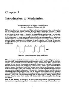
introductory digital communication texts, but we emphasize some specific points
in ... tool both for understanding and implementation of modern communication.
fulfillment of the requirements for the degree of. MASTER OF SCIENCE IN COMPUTER ENGINEERING. Thesis Committee. Prof. Sadiq M. Sait (Chairman). Prof.
The complexity of the manufac- turing process delayed the full exploitation of these devices for two more decades. Inste
[Allen99] D. Allen, et al., âA 0.2 µm 1.8 V SOI 550 MHz PowerPC Microprocessor with Copper. Interconnects,â Proceed
Jul 10, 2002 - I. Vranesic, Zvonko G. II. ... Brown, Vranesic: Fundamentals of Digital Logic with VHDL Design ..... The reviewers, William Barnes, New Jersey Institute ... Mellon University; Charles Silio, Jr., University of Maryland; Scott Smith, ..
1. Fundamentals of Digital System Design. ECE/CS 3700. Practice Exam for the
final. Spring 2009. Note: Time yourself for 2 hours. 30 total points. Closed book ...
Feb 25, 2008 - 0077221435 - (2008) Fundamentals of Digital Logic with VHDL Design - Ed. 3.pdf. 0077221435 - (2008) Funda
ECE 3700. Practise ... Closed book, closed notes, open minds, Do not panic.
Good luck. ... (2 points) Given the Pull-down network of a CMOS gate shown in
Fig.
Jul 10, 2002 - classical manual digital design and (2) illustrate clearly the way in which ... The electronic aspects of digital circuits are presented in Chapter 3. ...... J. Bhasker, Verilog HDL SynthesisâA Practical Primer, (Star Galaxy Publishi
Fundamentals of Digital Circuit Design. Cezary Zieliński. Publisher:
Wydawnictwo Naukowe PWN, Warsaw, 2003. (Published in Polish; contains 450
pages).
Fundamentals of Digital Circuit Design Cezary Zieliński Publisher: Wydawnictwo Naukowe PWN, Warsaw, 2003 (Published in Polish; contains 450 pages)
Objectives of the book: The course is targeted at all computer science, electrical, electronics, telecommunications and mechanical engineers who require the understanding of the functioning and the design of logic circuits at different levels of their complexity. The motif for this lecture is to show what are the major components and how to design digital logic for real time systems (e.g. mechatronics, robotics, computer systems). The lecture starts with combinational logic and ends with the design of large digital systems. The circuits integrated to a higher extent or more complex systems are designed using the already introduced components. For instance, a D-type flip-flop is designed using gates, then in turn functional blocks, such as counters or registers, are designed using those flip-flops, and finally functional blocks are used to construct data processing and control systems. In this way no phase of integration is left out giving the reader a full understanding of the field. As a result the readers should be able to design circuits and systems using elements of any scale of integration according to the needs of a project. Moreover, different approaches to designing the same circuits or systems are explained. All the concepts are explained explicitly showing the design process by simple yet real engineering examples. The mathematical background is kept to the minimum necessary level (rudimentary Boolean algebra is utilised). The examples are chosen in such a way that the inner workings of computers are explained, starting at the gate level, traversing ever more complex modules, and ending with microprogrammed machines. Table of contents: Foreword Notation 1. Introduction 1.1. Digital circuits 1.2. A short esej on designing 2. Combinational circuits 2.1. Basics of combinational circuit design 2.1.1. 2.1.2. 2.1.3. 2.1.4. 2.1.5. 2.1.6. 2.1.7. 2.1.8. 2.1.9.
Natural language description Formalization of the description Basic gates Creation of the circuit diagram Algebraic minimisation of logical expressions Cost evaluation Reduction of the number of gate types used NAND and NOR gates Functionally complete systems 1
Specification of logical functions Fundamentals of mnemonic methods of minimising logical functions Grays code Karnaugh maps Minimisation of logical functions using Karnaugh maps Dont care values Sum of Products normal form Factorization Prohibition Factorization and prohibition combined Product of Sums normal form Quine and McCluskeys method of minimisation Static hazard Dynamic hazard XOR gates
Iterative circuits with one-way flow of information between blocks Iterative circuits with two-way flow of information between blocks Cascade circuits Combinational circuits utilising multiplexers Combinational circuits utilising decoders Demultiplexers Read only memory Application Specific Integrated Circuits
Problem formulation Automaton state Graphs State transition and output table Coding D type flip-flop Flip-flop excitation tables Synchronous automaton realisation
Synchronous automaton structures Automaton Equivalence of complete (fully specified) automaton states Compatibility of incomplete (partially specified) automaton states Formalisation of the minimisation algorithms Realisation of a minimal automaton using D type flip-flops 2
3.2.7. 3.2.8. 3.2.9. 3.2.10.
JK flip-flop Realisation of a synchronous automaton using JK type flip-flops Partial equivalence of Moore and Mealy automatons Automatons without inputs
Problem formulation State graph and state transition and output table Coded state transition and output table Circuit realization
4.2. Basic definitions 4.2.1. Moore and Mealy automatons 4.2.2. Stable and unstable states 4.2.3. Design assumptions 4.3. Fundamentals of asynchronous circuit design 4.3.1. 4.3.2. 4.3.3. 4.3.4. 4.3.5. 4.3.6. 4.3.7. 4.3.8. 4.3.9. 4.3.10.
Time plots Assigning of states Primary state transition and output table Adding the missing information Minimisation of the number of states Incorrect coding Races Cyclic transitions State coding using hypercubes Coded state transition and output table and the realisation of the automaton
4.4. Alternative method of minimising asynchronous automatons 4.4.1. Phase one search for pseudoequivalent states 4.4.2. Phase two search for pseudocompatible states 4.4.3. An example of the utilization of the alternative method of minimising asynchronous automatons 4.5. Selected problems of asynchronous circuit design 4.5.1. 4.5.2. 4.5.3. 4.5.4. 4.5.5.
Assigning of states to sections of the time plots Elaboration of state transition and output functions Static RS type flip-flop Utilisation of static RS type flip-flops in the design of asynchronous automatons Asynchronous Mealy automatons
4.6. Asynchronous circuit design using state graphs 4.6.1. Problem formulation 4.6.2. Creation of the state graph 4.6.3. Minimization of the number of states and coding 3
4.6.4. Realization of an automaton Design exercises 5. Number representation 5.1. Historical notes 5.2. Positional representation of natural numbers 5.3. Positional representation of positive rational numbers 5.4. Radix transformation 5.5. Addition of numbers 5.6. Multiplication of numbers 5.7. Multiplication by radix 5.8. Division by radix 5.9. Representation of negative numbers 5.9.1. 5.9.2. 5.9.3. 5.9.4.
Signed magnitude representation of negative numbers Fixed point representation Diminished radix complement systems Radix complement systems
Exercises 6. Functional blocks 6.1. Internal structure of a functional block 6.1.1. 6.1.2. 6.1.3. 6.1.4. 6.1.5. 6.1.6.
Problem formulation Design phases Design of the synchronous part Design of the asynchronous (static) part Design of the combinational part Circuit diagram of the resulting functional block
6.2. Types of functional block inputs 6.2.1. Synchronic operations 6.2.2. Asynchronic static operations 6.2.3. Asynchronic dynamic operations 6.3. General survey of functional blocks 6.3.1. Combinational functional blocks 6.3.2. Sequential functional blocks Design exercises 7. Control and data processing digital systems 7.1. General introduction and formulation of the problem 7.2. System and its environment 7.3. Algorithm 7.3.1. Communication algorithm of the designed system with the external system 4
7.3.2. Multiplication algorithm 7.4. Data path subsystem 7.5. An improved multiplication algorithm and the resulting data path subsystem 7.6. Structure of a digital system 7.7. Signals controlling a data path subsystem 7.8. Methods of transforming flow charts into state graphs 7.9. Moore control automaton 7.9.1. Transformation of the flow chart into a state graph 7.9.2. Realization of a minimal control automaton 7.9.3. Problems with a Moore automaton 7.10. Mealy control automaton 7.10.1. Transformation of the flow chart into a state graph 7.10.2. Realization of a minimal control automaton 7.10.3. Problems with a Mealy automaton 7.11. Realization of the control subsystem as a sequencer 7.11.1. Transformation of the flow chart into a sequencer 7.11.2. Realization of a Moore control sequencer 7.11.3. Realization of a Mealy control sequencer 7.12. Initialization of the control subsystem 7.13. Microprogrammed control subsystems 7.13.1. Microprogrammed Moore control automaton 7.13.2. Microprogrammed Mealy control automaton 7.13.3. Microprogrammed machines 7.14. An outline of yet another project 7.14.1. 7.14.2. 7.14.3. 7.14.4.
Problem formulation Data path subsystem and the flow chart Priority selector Throughput analysis of the pulse generator
Design exercises 8. Concurrent digital systems 8.1. Problem formulation 8.2. Petri nets 8.2.1. 8.2.2. 8.2.3. 8.2.4. 8.2.5. 8.2.6. 8.2.7.
Petri net definition Marked Petri net Functioning of a marked Petri net A few useful terms Example of Petri net utilization Reachibility tree Enhanced Petri net
8.3. Concurrent system controller 5
8.3.1. 8.3.2. 8.3.3. 8.3.4. 8.3.5.
Creation of a Petri net Analysis of a Petri net Control automaton state transition graph Control automaton Company development
Design exercise 9. Quo vadis? (Where from here?) Appendix A. Boolean algebras Appendix B. Automata and languages Exercises Appendix C. Historical notes References Index