Abstractâ Because of its low maintenance and robustness, induction motors have many applications in the industries. Most of these applications need fast and ...
Fuzzy Controller for Three Phases Induction Motor Drives Ali M. Eltamaly, A. I. Alolah, and Basem M. Badr EE Dept., College of Engineering, King Saud University, Riyadh, Saudi Arabia. Abstract— Because of its low maintenance and robustness, induction motors have many applications in the industries. Most of these applications need fast and smart speed control system. This paper introduces a smart speed control system for induction motor using fuzzy logic controller. Induction motor is modeled in synchronous reference frame in terms of dq form. The speed control of induction motor is the main issue achieves maximum torque and efficiency. Two speed control techniques, Scalar Control and Indirect Field Oriented Control are used to compare the performance of the control system with fuzzy logic controller. Indirect field oriented control technique with fuzzy logic controller provides better speed control of induction motor especially with high dynamic disturbances. The model is carried out by using Matlab/Simulink computer package. The simulation results show the superiority of the fuzzy logic controller in controlling three-phase induction motor with indirect field oriented control technique. Keywords— Vector control, Fuzzy logic, Induction motor drive.
I.
INTRODUCTION
The variable speed systems took a great importance in the industry and in the research and require multidisciplinary knowledge in the field of the electric genius [1]. The induction motor is considered since its discovery as actuator privileged in the applications of constant speed, and it has many advantages, such as low cost, high efficiency, good self starting, its simplicity of design, the absence of the collector brooms system, and a small inertia [1-3]. However, induction motor has disadvantages, such as complex, nonlinear, and multivariable of mathematical model of induction motor, and the induction motor is not inherently capable of providing variable speed operation [3-4]. These limitations can be solved through the use of smart motor controllers and adjustable speed controllers, such as scalar and vector control drive [1, 5]. Control (FOC) or vector control was invented in the late 1960 [1]. As the induction motors were controlled using scalar control methods like the volt-hertz control, the magnitude and frequency of the stator voltages are determined from steadystate properties of the motor, which leads to poor dynamic performance. In FOC the magnitude, frequency and instantaneous position of voltage, current and flux linkage vector are controlled and valid for steady state as well as transient conditions. FOC is a technique that provides a method of decoupling the two components (d and q) of stator current: one producing the air gap flux and the other producing the torque. Therefore, it provides independent control of torque and flux, which is similar to a separately excited DC machine. The FOC schemes are classified into two groups: the
978-1-4244-7107-2/10/$26.00 ©2010 IEEE
direct method of field orientation proposed by Blaschke [6] and the indirect method of field orientation proposed by Hasse [7]. The direct method requires flux acquisition, which is mostly obtained by computation techniques using machine terminal quantities, where as indirect method avoids the requirement of flux acquisition by using known motor parameters to compute the appropriate motor slip speed (Zsl) to obtain the desired flux position. The scheme of indirect is simpler to implement than the direct method of FOC hence, indirect method has become more popular [8-12]. Conventional control of an induction motor is difficult due to strong nonlinear magnetic saturation effects and temperature dependency of the motor’s electrical parameters. As the conventional control approaches require a complex mathematical model of the motor to develop controllers for quantities such as speed, torque, and position. Recently, to avoid the inherent undesirable characteristics of conventional control approaches, Fuzzy Logic Controller (FLC) is being developed. FLC offers a linguistic approach to develop control algorithms for any system. It maps the input-output relationship based on human expertise and hence, does not require an accurate mathematical model of the system and can handle the nonlinearities that are generally difficult to model. This consequently makes the FLC tolerant to parameter variation and more accurate and robust [13-15]. This paper will demonstrate the improvement in the motor drive performance using FLC to implement scalar and Indirect Field Oriented Control (IFOC). This paper shows the space phasor model of three-phase induction motor in section II. In section III, various control techniques are used to control speed and improve performance of induction motor drive using fuzzy control. The implementation of scalar and vector control using FLC in Matlab/Simulink environment and their simulation results are given to demonstrate and compare between scalar and vector control in section IV. Conclusion and reference are mentioned in the last section. II.
INDUCTION MOTOR MODEL
The dynamic model of the induction motor is derived by transforming the three-phase quantities into two phase direct and quadrature axes quantities. The equivalence between the three-phase and two-phase machine models is derived from the concept of power invariance [16]. Induction motor model in the synchronous reference frame is shown in (1) and subscript e denotes this reference frame, the model is discussed in more details in [8]:
ªveqs º « e» «vds » «veqr » « e» ¬«vdr ¼»
Ȧs Ls LmP Ȧs Lm º ªieqs º ª Rs � Ls P « » « �Ȧ L Rs � Ls P LmP »» «ieds » � Ȧs Lm s s « e (1) « LmP (Ȧs � Ȧr )Lm Rr � Lr P (Ȧs � Ȧr )Lr » «iqr » » « » « LmP � (Ȧs � Ȧr )Lr Rr � Lr P ¼ ¬«iedr ¼» ¬� (Ȧs � Ȧr )Lm
The electromagnetic torque is:
ª «¬Te
3P º Lm(i eqsi edr � i edsi eqr )» 22 ¼
(2)
Where Zs: Synchronous speed, Zr : Electrical speed (rotor speed), P: Number poles of IM, Te: Electromagnetic torque, Lm: Mutual inductance, Ls: Stator leakage inductance, Lr: Rotor leakage inductance, Rs: Stator resistance, Rr : Rotor resistance, i eqs : Stator current in synchronous frame on q-axis,
i eds : Stator current in synchronous frame on d-axis, i edr : Rotor current in synchronous frame on d-axis, i eqr : Rotor current in synchronous frame on q-axis, v eqs : Stator voltage in synchronous frame on q-axis,
v eds : Stator voltage in synchronous frame on d-axis,
Odr: Rotor flux on d-axis, Oqs: Stator flux on q-axis, Oqr : Rotor flux on q-axis. The stator and rotor flux-linkage phasors are the resultant stator and rotor flux linkages and are found by taking the vector sum of the respective d and q components of the flux linkages. Note that the flux-linkage phasor describes its spatial distribution. Instead of using two axes such as the d and q for a balanced polyphase machine, the flux-linkage phasors can be thought of as being produced by equivalent single-phase stator and rotor windings, as space phasor model that has many advantages: x The system equations could be compact and be reduced from four to two; x The system reduces to a two-windings system like the dc machine, hence the apparent similarity of them in control to obtain a decoupled independent flux and torque control as in the dc machine; x Easier analytical solution of dynamic transients of the key machine variables, involving only the solution of two differential equations with complex coefficients. Such an analytical solution improves the understanding of the machine behavior in terms of machine parameters, leading to the formulation of the machine design requirements for variable-speed applications. The space phasor model of the induction motors can be presented in state space equations from previous equation, so it can be expressed in the synchronously rotating d-q reference frame as follows [17-18]:
v eqr : Rotor voltage in synchronous frame on q-axis,
ܺሶ ൌ ܺܣ ݑܤ
e dr
v : Rotor voltage in synchronous frame on d-axis.
Where
The dynamic equations of the induction motor in synchronous reference frames can be represented by using flux linkages as variables. This involves the reduction of number of variables in dynamic equations, which greatly facilitates their solution. The flux-linkages representation is used in motor drives to highlight the process of the decoupling of the flux and torque channels in the induction machine. The stator and rotor flux linkages in the synchronous reference frames are defined as in [8, 12, 16]: (3) Ȝ e Lsi e � Lmi e
ܺ ൌ ቂ i ds
qs
qs
qr
e Ȝ ds
Lsi eds � Lmi edr
(4)
Ȝ eqr
Lri eqr � Lmi eqs
(5)
Ȝ edr
Lri edr � Lmi eds
(7)
e qm
Lm(i � i )
(8)
Lm(ieds � i edr )
(9)
Ȝ
Ȝ edm
e qs
Where Odm: Mutual flux on d-axis, Oqm: Mutual flux on q-axis, Ods: Stator flux on d-axis,
e qr
e
ଵ ఙ�ೞ
ܤൌ� Ͳ Ͳ Ͳ ܽଵ െݓ
ܣൌ �ோೝ ೝ �
Ͳ Where;
Ȝ edr
i eqs
Ͳ ଵ ఙ�ೞ
Ͳ Ͳ ݓ
ܽଶ
ܽଵ
െ
Ͳ �ோೝ ೝ �
�௪ೝ ఙ�ೞ �ೝ ି�ோೝ ೝ �
െݓ � ݓ
ሺͳ െ ߪሻܴ ܴ௦ െ� � ߪܮ௦ ߪ�ܮ ܮ �ܴ ܽଶ ൌ � � ߪ�ܮ௦ �ܮ ଶ
ܽଵ ൌ � െ
ߪ = ͳ െ�
்
Ȝ eqr ቃ and ݑൌ � ሾ v eds
మ
ೞ �ೝ
.
�௪ೝ ఙ�ೞ �ೝ
ܽଶ ݓ െ � ݓ ି�ோೝ ೝ �
(9)
v eqs ሿ்
III.
THE PROPOSED CONTROL SYSTEM
Due to poor dynamic performance in open-loop of induction motor, various control technique have been widely used in many applications to achieve high dynamic performance, get tracking speed, and generate maximum torque of induction motor, namely scalar control and FOC.
inherent low speed problems and is thus preferred in most systems which must operate near zero speed [19-21].
A.
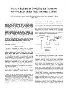
Scalar Control Scalar control as the name indicates, is due to magnitude variation of the control variables only, and disregards the coupling effect in the machine. Scalar control has been widely used in industry, the fact that they are easy to implement. The scalar control strategy is based on simplified volts/Hertz control scheme with stator frequency regulation as shown in Fig.1. As the controller generates the slip speed Zsl signal that is added with electrical speed that yields synchronous speed Zsl that is used in induction motor model with synchronous reference frame and generate the voltage command through Volts/HZ function to keep flux constant [19-20]. B. Vector control Vector control of an induction motor is analogous to the control of a separately excited DC motor. In a DC motor the field flux Mf produced by the field current If is perpendicular to the armature flux Ma produced by the armature current Ia. These fields are decoupled and stationary with respect to each other. Therefore, torque is controlled by armature current the field flux remains unaffected enabling a fast transient response. As scalar control technique is relatively simple to implement but gives a sluggish response because of the inherent coupling effect due to torque and flux being functions of current and frequency. The vector approach overcomes the sluggish transient response associated with scalar control of induction motors [18-20].
Figure 2. Phasor diagram of the vector controller.
C.
Indirect Field Oriented Control
The rotor voltage equations of the induction motor in the synchronous reference frame equal zero because of squirrel cage of induction motor and can be written as: (10) ܴ i e + p Ȝ e + ݓȜ e =0
qr
௦
qr
dr
(11) ܴ i + p Ȝ ݓ௦ Ȝ eqr =0 As the rotor flux ߣ lays on d-axis of the synchronous e dr
e dr
frame, so the flux equation can be written as:
ߣ ൌ � Ȝ edr
(12)
Ȝ eqr = 0
(13)
Rotor currents can be derived from the flux linkage equations as following: (14) i e = െ � i e qr
e dr
i ൌ
Figure 1. Block diagram of scalar controller for IM.
In vector control, the current phasor is produces the rotor flux Ȝr and the torque Te. The component of current producing the rotor flux phasor should be in phase with Ȝr. Therefore, resolving the stator current phasor along Ȝr reveals that the component if is the field-producing component. The perpendicular component iT is hence the torque-producing component, as shown in Fig. 2. Vector control schemes are classified according to how the field angle is acquired. If the field angle is calculated by using terminal voltages and currents or Hall sensors or flux-sensing windings, then it is known as direct vector control. The field angle can be obtained by using rotor position measurements but not any other variables, such as voltages or currents; using this field angle leads to a class of control schemes known as indirect vector control. Indirect field orientation does not have
ೝ qs ܮ e െ ݉ � qs ೝ ݎܮ
ఒೝ
(15)
i
From previous equations, so stator currents can be derived from the flux linkage equations and slip speed that can be written: �ఒ (16) i eqs = ݓ௦ ೞ ೝ ൌ � ݅ ் � e ds
i ൌ
ଵ
ோೝ ೝ ௗ�ఒೝ
ሾ ߣ
ݓ௦ ൌ
�
ோೝ ௗ௧ �ோೝ �
�ሿ ൌ � ݅
(17) (18)
ೝ �ఒೝ
Since the current component responsible for generating field must be in phase with the rotor flux, the d-axis stator current is established as ݅ . Hence the perpendicular
component ݅௦ must be the torque-producing factor and is ݅ ் ,
the Phase of the current signal is the sum of ș (field angle) and ș ் where:
ș ் ൌ � ି݊ܽݐଵ �
݅ܶ � ݂݅ �
(19)
The electromagnetic torque is written as:
ܶ ൌ �
ଷ�� ସ�ೝ
�ߣ �݅ ்
(20)
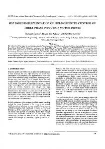
Fig. 3 shows the implementation block of indirect vector control. As FOC block contains the previous equations that yield the stator current and the field angle. The field angle is the sum of slip angle ș௦ and rotor angle ș that are obtained by the integration of slip speed and rotor speed respectively. The stator currents are calculated and are sent to the inverter that generates pulses to drive the induction motor [22-23].
Figure 3. Indirect Field Oriented Control of IM.
D.
Fuzzy Logic Controller FLC is a technique to embody human-like thinking into a control system. FLC can be designed to emulate human deductive thinking, that is, the process people use to infer conclusions from what they know. FLC has been primarily applied to the control of processes through fuzzy linguistic descriptions [15, 18]. FLC is utilized to design controllers for plants with complex dynamics and high nonlinearity model. In a motor control system, the function of FLC is to convert linguistic control rules into control strategy based on heuristic information or expert knowledge. FLC approach is very useful for induction motor speed drives since no exact mathematical model of the induction motor or the closed-loop system is required [25]. FLC has a fixed set of control rules, usually derived from expert’s knowledge. The membership function (MF) of the associated input and output linguistic variables is generally predefined on a common universe of discourse. For the successful design of FLC’s proper selection of input and output scaling factors (gains) or tuning of the other controller parameters are crucial jobs, which in many cases are done through trial and error to achieve the best possible control performance [19, 25]. The structure of FLC is shown in Fig.4. The structure shows four functions, each one materialized by block [1, 26].
x A fuzzification interface, the fuzzy control initially converts the crisp error and its rate of change in displacement into fuzzy variables; then they are mapped into linguistic labels. Membership functions are defined within the normalized range (-1, 1), and associated with each label: NB (Negative Big), NM (Negative Medium), NS (Negative Small), NVS (Negative Very Small), ZE (Zero), NPS (Positive Very Small), PS (Positive Small), PM (Positive Medium), and PB (Positive Big). Seven MFs are chosen for e(pu) and ce(pu) signals and nine for output. All the MFs are symmetrical for positive and negative values of the variables. Thus, maximum 7ɯ7 = 49 rules can be formed as tabulated in Table 1. The surface error and membership functions for the inputs (error and change of error) and output of fuzzy control for scalar and vector control are shown in Fig. 5. x A knowledge base (a set of If-Then rules), which contains the definition of the fuzzy subsets, their membership functions, their universe discourse and the whole of the rules of inference to achieve good control. x An inference mechanism (also called an “inference engine” or “fuzzy inference” module), which is heart of a fuzzy control, posses the capacity of feign the human decisions and emulates the expert’s decision making in interpreting and applying knowledge about how best to control the plant. x A defuzzification interface, which converts the conclusions of the inference mechanism into actual inputs for the process. In this work; Center Of Area (COA) is used as a deffuzification method, which can be presented as;
ܺ ௦ ൌ �
σ సభ ௫ ఓಲ ሺ௫ ሻ�
(21)
σ సభ ఓಲ ሺ௫ ሻ�
Where n : Number of the discrete elements. ݔ : The value of the discrete element ߤ ሺݔ ሻ : The corresponding MF value at the point ݔ Ǥ The gains G1, G2, and G3 are scaling factors to adapt the variables to the normalized scale. However, the inference strategy is the mamdani algorithm, so the if-then rules for fuzzy scalar control and fuzzy vector control for torque control will be forty nine rules. Tabel 1. Rules FOR FUZZT CONTROLLER
ce
e NB NM NS Z PS PM PB
NB NB NB NB NM NS NVS Z
I.
NM NB NB NM NS NVS Z PVS
NS NB NM NS NVS Z PVS PS
Z NM NS NVS Z PVS PS PM
PS NS NVS Z PVS PS PM PB
PM NVS Z PVS PS PM PB PB
PB Z PVS PS PM PB PB PB
SIMULATION RESULTS
Simulation results have been realized under Matlab/Simulink environment. A simullink model is carried out to realize induction motor equation (9) using parameters in Table 2. Figure 4. Structure of fuzzy control
Table 2. PARAMETERS OF INDUCTION MACHINE [27] Rated voltage
220 v
Rated load torque
10 N.m
Pole pairs
2
Stator resistance
3.1 ߗ
Rated speed
1500 rpm
Rotor resistance
Rotor inertia
0.2 Kg.m 0.002 N.rad/sec
Stator inductance
1.7 ߗ 0.328 H
Rotor inductance
0.337 H
Mutual inductance
0.32 H
Damping factor Rated current
6.4 A
Fig 6 and fig 7 show the implementation of fuzzy controller for scalar and vector control respectively in Matlab/Simulink, where the implementation of fuzzy controller for vector control has three fuzzy controllers: speed, flux, torque controller. As the sample time is selected as 0.1 msec. The obtained results of speed, torque and flux for closed-loop of scalar and vector control using fuzzy control are shown in Fig 8 to Fig.11 respectively. Fig 8 shows the speed of the induction motor using scalar and vector control, as the speed in scalar control tracks the reference speed, but it has small overshoot, when the reference change suddenly and load torque is applied at 0.8 sec and faster response than vector control, however, the speed of vector control tracks the reference, and it has more delay time than scalar control and smooth response, when the reference change suddenly and applying load torque. Although, Fig. 9 shows the developed electromagnetic torque for scalar and vector control, that achieve good tracking. As in vector control the developed control has smoother performance than scalar control, when changing speed and applied load torque at 0.8 sec. Fig. 10 and Fig 11 show the d-q of flux, as in scalar control, the fluxes have oscillation, when the reference changes suddenly and load torque is applied, however, in vector control, the flux have smooth and fixed response, in transient conditions, when the reference changes suddenly and load torque is applied.
(a)
Figure 6. Scalar control of induction motor in Matlab/Simulink
Figure 7. The implementation of vector control of induction motor in Matlab/Simulink
Figure 8. Speed response of scalar and vector control
(b)
(c) Figure 5. (a) Inputs membership function, (b) Output membership function, (c)Surface error.
Figure 9. Torque response of scalar and vector control
[7] [8] [9] [10] [11] [12] [13] [14] Figure 10. Flux response of scalar control [15] [16] [17] [18] [19] [20]
Figure 11. Flux response of vector control
II.
Fuzzy logic controller shows fast control response with three-phase induction motor. Two different control techniques are used with Fuzzy logic controller which are, scalar and field oriented control techniques. Fuzzy logic controller system shows better response with these two techniques. Meanwhile, the scalar controller has a sluggish response than Field oriented control because of the inherent coupling effect in field and torque components. However, the developed fuzzy logic control with field oriented control shows fast response, smooth performance, and high dynamic response with speed changing and transient conditions. REFERENCES [1] [2] [3] [4] [5] [6]
[21]
CONCLUSIONS
A. Mechernene, M. Zerikat and M. Hachblef, “Fuzzy speed regulation for induction motor associated with field-oriented control”, IJ-STA, volume 2, pp. 804-817, 2008. Leonhard, W.,” Controlled AC drives, a successful transfer from ideas to industrial practice”, CETTI, pp: 1-12, 1995. M. Tacao, “Commandes num ƴ rique de machines asynchrones par lagique floue”, thƴ se de PHD, Universitƴ de Lava- facultƴ des science et de gƴ nie Quƴ bec, 1997. Fitzgerald, A.E. et al., Electric Machinery, 5th Edn, McGraw-Hill, 1990. Marino, R., S. Peresada and P. Valigi, “Adaptive input-output linearizing control of induction motors”, IEEE Trans. Autom. Cont., 1993. F. Blaschke, “The principle of field orientation as applied to the new transvector closed-loop control system for rotating-field machines”, Siemens Rev., 1972.
[22] [23] [24] [25] [26] [27]
K. Hasse, “Zum Dynamischen Verhalten der Asynchronmachine bei Betriek Mit Variabler Standerfrequenz und Standerspannung,” ETZ-A, 1968. B.K. Bose, “Power electronics and variable frequency drives” IEEE press standard publishers, 1997. I. Boldea, S.A Nasar, Vector Control of AC Drives, CRC Press, London, 1992. W. Leonhard, Control of Electric Drives, Springer Verlag, Berlin, 1985. P. Vas, Vector control of AC machines, Oxford press, 1990. R. Krishnan, Electric Motors Drives Modeling Analysis and control, Publication Prentice Hall of India, 2002. S. Beierke, C. von Altrock, “Fuzzy logic enhanced control of an induction motor with DSP”, 5th IEEE International. Conf. on Fuzzy Systems, New Orleans, LA, September 1996. R.J. Spiegel, M.W. Turner, V.E. McCormick, “Fuzzy-logic-based controllers for science optimization of inverter-fed induction motor drives”, ELSEVIER Journal (available at www.scincedirect.com), 2003. Ali Zilouchian, Mo Jamshidi, Intelligent Control Systems Using Soft Computing Methodologies, CRC Press LLC, 2001. P. C. Sen, Princibles of Electric Machines and power electronics, Wily, 2nd edition, 1996. N.S.Gehlot and P.J.Alsina, “A discrete model of induction motors for real time control applications,” IEEE Trans. Ind. Electron., vol. 40, pp. 317-325, June 1993. V. Chitra, and R. S. Prabhakar, “Induction Motor Speed Control using Fuzzy Logic Controller”, World Academy of Science, Engineering and Technology, 2006. B. K. Bose, Modern Power Electronics and AC Drives, Prentice-Hall, Upper Saddle River, NJ, 2002. F. Betin, D. Depermet, P. Floczek, A. Faqir, V. Lanfranchi, D. Pinchon, C. Goeldel, A. Capolino, “ Fuzzy Logic Scalar Control For Induction Machine Drive : Comparison With Classical Drive” International AEGEAN Conference on Electrical Machines and Power Electronics. 27 – 29 June 2001. Rajesh Kumar, R.A. Gupta and S.V. Bhangale, “Microprocessor/Digital Control And Artificial Intelligent Vector Control Techniques For Induction Motor Drive”, IETECH Journal of Electrical Analysis, 2008. Heber, B., Xu, L. and Tang, Y., “Fuzzy Logic Enhanced Speed Control of an Indirect Field- Oriented Induction Machine Drive,” IEEE Transaction on Power Electronics, Vol. 12, 1997. Krishnan, R., Electric Motor drives: Modeling, Analysis and Control, Prentice Hall, New Jersey, 2001. Lin, F. and Liaw, C., “Control of Indirect Field-Oriented Induction Motor Drives Considering the Effects of Dead-Time and Parameter Variations,” IEEE Transaction on Industrial Electronics, Vol. 40, 1993. Y. Miloud, A. Draou, “Fuzzy Logic Speed Control of an Indirect FieldOriented Induction Machine Drive”, Conf. Rec. IEEE/IECON’01 Denver, USA, pp. 2111-2116, Nov. 2001. Kevin M. Passino, Fuzzy Control, Addison Wesley Longman, 1998. Nyein Nyein Soe, Thet Thet Han Yee, and Soe Sandar Aung, “Dynamic Modeling and Simulation of Threephase Small Power Induction Motor”, World Academy of Science, Engineering and Technology 42, 2008.