Page 1 ... Dept. of Electrical Engineering,. National Taiwan ... Science and Technology, ... Absfract - A sensorless vector controller for induction motor ... synchronous speed of motor drives using the error of reactive ..... The MRAS-based sensorless induction motor drive ... shows the block diagram of hardware configuration.
Sensorless Vector Controller for Induction Motor Drives with Parameter Identification Shyh-Shing Perng
Yen-Shin Lai, Member, IEEE
Chang-Huan Liu, Member, IEEE
Dept. of Electrical Engineering, National Taiwan University of Science and Technology, 43, Sec. 4, Keelung Rd., Taipei, Taiwan, R. 0. C.
Dept. of Electrical Engineering, National Taipei University of Technology, 1, Sec. 3, Chung-Hsiao E. Rd., Taipei, Taiwan, R. 0. C.
Dept. of Electrical Engineering, National Taiwan University of Science and Technology, 43, Sec. 4, Keelung Rd., Taipei, Taiwan, R. 0. C.
Absfract - A sensorless vector controller for induction motor drives [l]based on the theory of Model Reference Adaptive System (MRAS) [2] has been presented, which identifies synchronous speed of motor drives using the error of reactive
power as the reference input of adaptation mechanism. Moreover, as shown in [l] the MRAS-based synchronous speed identification scheme requires neither rotor time constant nor stator resistance in both adjustable and reference models, However, rotor resistance is still used for the estimation of shaft speed. In this paper, a stator resistance identification scheme based upon MRAS using the error of active power as the reference input of adaptation mechanism and details about the stability of the identification scheme will be presented. Moreover, the rotor resistance is adjusted using the variation rate of stator resistance [3]. Simulation and experimental results will be presented to confirm the theoretical analysis.
Nomenclature
x",
2
total leakage factor; CY = I-( L, / L, LJ rotor time constant; z, = L, / R, sampling period of digital implementation inertial of motors variable of the Laplace Transform back electromagnetic force (EMF)
0
*r
Ts Jm S
e:,
reactive power of machine
Q P
actual power of machine L; = L: /(L,z,oL,) value of parameter state error of MRAS e; - i; =pi,-Re(zI:) output error ofMRAs output error of MRAS E;; =P-P' output error of MRAS E" w -=Q-Q' ,,:=,,A + J V4sr stator voltage G
~
2;
=
U:
a referring to a stationary fiame linked to phase A r
of stator windings referring to the rotor flux frame
d q s r
d-axis component q-axis component stator component rotor component
*
xo
Ax
deviation of x from the equilibrium point xo
Re(x)
real part of X
h(x>
imaginary'part ofx
~
X
q. Wsl
P R, Rs Lr LS
Lm
1998 IEEE
magnetizing current
;
rotor flux stator flux
I. INTRODUCTION It is well known that the advantages of speed sensorless motor drives over conventional closed-loop system with shaft sensors include the reduction of cost and size of drives. A variety of methods have been proposed which heavily rely upon plant parameters. A comprehensive review of sensorless control of induction motor drives can be found in reference [4]. Sensorless induction motor control based upon the theory of Model Reference Adaptive System (MRAS) [2] provides an alternative way for the development. However, the method shown in [5] requires both rotor and stator resistors, and integral operation which involves initial value problem. Although, integration operation is not required in [ 6 ] ,rotor time constant which is sensitive to temperature variation, is still necessary for the adjustable model. To deal with this problem, a sensorless controller [l] based on MRAS has been presented by the authors. The proposed MRAS scheme requires neither rotor time constant nor stator resistance in both adjustable and reference models. Moreover, no integral operation is required and therefore provides wider bandwidth for speed
synchronous speed rotor speed slip frequency differential operator rotor resistance stator resistance rotor self-inductance stator self-inductance mutual inductance
0-7803-4503-7/98/$10.00
Jz&
I.,
Symbols me
rotor current stator current
LT,; + I ;
a; = L,~; + L,~; a; = Q; + L ~ ~
reference or command value of X estimated (calculated) or feedback value of x conjugate of x equilibrium point of x
2
+
I,; =
D:
X
Iir + / I ;
1008
control. However, as shown in [ l ] rotor resistance is still required for the estimation of mechanical speed. In this paper, a stator resistance identification scheme based upon the theory of MRAS using the error of active power as the reference input of adaptation mechanism is presented. Therefore, the rotor resistance is adjusted using the variation rate of stator resistance [3]. The paper is organized as follows. The theory for the development and stability analysis of the proposed MRASbased identification scheme are presented, and followed by the simulation and experimental results codinning the theoretical analysis. 11. THEORY MRAS-based Synchronous Speed IdentiJication [ I ] The motor voltage referring to rotor flux fi-me can be derived as follows.
A.
B.
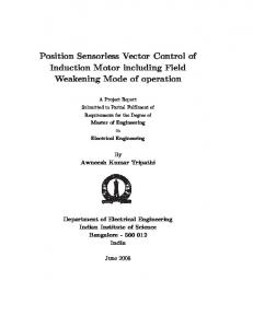
New MRAS-based Stator Resistance IdentiJication The active power of machine can be shown by (9) and rewritten as shown in (1 0) by substituting (2) and (3) into (9).
(10) Substituting (6) into (lo), the active power can be derived as shown in (1 1>. P = R, [(iiS)2 + (i&)2]+ we(1 - o)t,i&ii, + oLsii8piis (1 1) By the theory of MRAS [ 2 ] ,the stator resistance can be identified using (9) and (11) as reference and adjustable models respectively, as shown in Fig. 2.
C.
Equations (2) and (3) are substituted into (4), which is the reactive power of machine, thereby resulting in (5),.
Substituting the stator flux equation shown in (6) into shown in (5) can be rewritten as shown in (7).
(9, the equation of reactive power
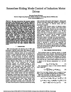
According to the theory of MRAS, (4) and (7) can be used as the reference and adjustable models, respectively, to identify the synchronous speed. The block diagrml for the new MRAS synchronous speed identification scheme is shown in Fig. 1. Noting that the reactive power shown in (4) and (7) does not contain either rotor resistance nor stator resistance. Moreover, the calculations of reactive power for both reference and adjust models shown in (4) and (7), respectively do not require any integration operation. It is important to note that the error signal, E: , defined in Fig. 1, of the new MRAS synchronous speed identification can be derived '%om Fig. 3 and is shown as follows.
[
(ii,r+ L, (i;
CUI,= ikvis - iisvL - we o~~
r]
~
ikoL,pii,
Rotor Resistance Adaptation It has been shown [7] that rotor resistance and shaft speed can not be estimated simultaneously without injecting additional exciting signal for inverter control. One of the simplest approaches to estimate both rotor resistance and shaft speed is to adjust rotor resistance using the variation rate of stator resistance [3] as shown in (12).
'
reference model
E::
adjustable model I
(
he
-r
pG&zi-l machanism
Fig. 1 MRAS-based synchronous speed identification scheme [11
+ ii,L,pi;
(8) More details about the proof of stability of the MRAS-
based synchronous speed identification scheme can be found in [l].
0-7803-4503-7/98/$10.00
1998 IEEE
I009
Fig. 2 New MRAS-based stator resistance identification scheme
Similar results for the estimated EMF,
:z , can also be
derived by the same process and is shown as follows. where
&, i B e o
are initial values of rotor and stator
resistors respectively.
D. Stability Analysis The voltage and flux equations referring to the stationary frame are as follows.
Let E~ = e, - 2, , the state error equation, derived from (23) and (24), is given by
v$ = RJ," +PA:
A:
= L,if
1; = L,i$
p R= -(Li
+ jwrA:
0 = Rri: +pa:
+ L,iF
=AER
+&pi: Lr
The equivalent nonlinear feedback system is shown in Fig. 4. As shown in Fig. 4, the stator resistance is identified using the adaptation mechanism and (25). Moreover, the system is hyperstable [2] if the linear timeinvariant forward-path transfer matrix is strictly positive real and the nonlinear feedback block, including the adaptation mechanism, satisfies the Popov ' s criterion [SI as shown in (26).
(17)
j:Re(EiW)lt
Li Pi; L, across the magnetizing inductance shown in Fig. 3 is defined as follows.
induced electromagnetic force (EMF), e:
[R,if
-
j u , ] , W = Lii:(Rs - R s )
rr
Moreover, the associated equivalent circuit can be derived fkom (17) and (18), as shown in Fig. 3 and the
-
W
1 A = [-(Lk +-)+
2
e: = v,"
-
where
+ LriF = L,i:
-t aL,pi,"
+ j u r E R - L;i:(R, -is)
rr
Substituting the flux equations shown in (15 ) and (16), into voltage equations, (13) and (14), the machine equations become v," = R,if
1
+-)E~
=j:
(Edri2 +Eqri$)im(Rs-A,) 2 -T:
b't1 2 0
7
(26) where
ro2
is a positive constant.
+oLspif]
L; 1 . e: =-[--