2013 IEEE International Conference on Emerging Trends in Computing, Communication and Nanotechnology (ICECCN 2013)
250
Fuzzy Logic Based Railway Track Condition Monitoring System Chellaswamy. C1, Akila. V2, Dinesh Babu. A3, Kalai Arasan. N4 1,2,3
Assistant Professor, Department of ECE, SRM University, Chennai, India. 4 Programmer, Department of ECE, SRM University, Chennai, India. 1
[email protected],
[email protected],
[email protected],
[email protected] Abstract— In recent years, the need to improve the quality and comfort of railway passengers, there has been increased demands to reduce the level of noise and vibration, experienced during travel. Different researches have focused on reducing the level of vibration. Track irregularities are the main causes of vibration and thus carefully monitor the parameter to improve the ride quality. Vibration may arise vertically and laterally, in this vertical vibration is higher. In this paper, we proposed a new method called Fuzzy Track Monitoring System (FTMS) for estimating the irregularities present in the railway track at running time. The vibration sensor is mounted on the axel box and the bogie of the train for measuring the acceleration in the lateral and vertical directions. The system automatically tracks the location of vibration and sends it to the central office. The performance of proposed approach was studied and it proves that the proposed approach is capable for real time measurements. Keywords—vibration measurement; monitoring; vibration sensor; fuzzy controller
I.
track
condition
INTRODUCTION
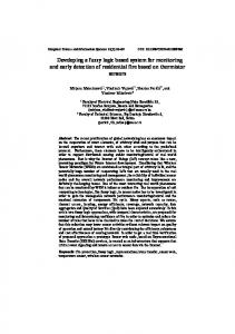
Modern vehicles are electronically monitored and controlled. With the entry of new technologies, different sensors are used for monitoring different parts of the vehicle. The wheel sets of trains are consists of axels, which are connected to the bogie and suspension system as shown in fig. 1. Usually the sensor information is readout by an electronic unit connected through wire or wireless. Railway vehicle adopt many pneumatic system and the electronic measuring system which provides more accuracy than other system. The model based fault detection and isolation system is to develop the appropriate models for describing the dynamic behavior of the railway vehicle [1]. The reliability of suspension system of secondary lateral and yaw-dampers in railway vehicle are lower. In this consequence, a plan view of a half body vehicle is developed intentionally for finding the fault present in the two elements. Different filters have been studied and the Kalman filter based state estimation method is suitable for appropriate result. The performance of model based railway vehicle condition monitoring system is evaluated through simulation [2]. For measuring the condition solid state inertial sensors have been used and the simulation is carried out. Contact force estimation in wheel-rail interface is carried out using Kalman-Bucy estimation technique [3]. The model is considered for full length body of the vehicle
and signal is measuring not only from yaw also from two bogies with the accompanying four wheel sets. Different forces like creep, gravitational and suspension and position are considered for finding the estimation. Vehicle health monitoring system reduces the maintenance and inspection requirement. A forecasting model has developed to investigate the behaviour of vertical acceleration of a moving locomotive using ten different regression algorithms are compared [4]. The algorithms are compared with complexity, RMS error and correlation coefficient and support vector machine recession is suitable for machine learning and monitoring. Two types of testing, bench and field test was carried out for ionospheric scintillation monitoring [5]. Bench test employed a single channel GPS simulator and demonstrates both qualitative and quantitatively, the signal strength fluctuate at the rate up to 25 Hz. Whereas field test verify the synchronize data collection and irregularities observed from other instruments. This system can monitor and record the scintillation from several GPS simultaneously for study the correlation of multiple receivers. The performance of GPS can be improved by a simple architecture called GPSinertial systems with ultra-tight integration [6]. The parameters such as higher phase-tracking bandwidth, and more resistance to radio frequency interference can be improved. The ultra tight integration can be achieved even with automotive-grade inertial sensors and common TCXO oscillators. The simulation result with these inexpensive components demonstrated meaningful advantages over a system with traditional tracking loops, including a 14dB improvement in phase-noise suppression and robustness. The application of tracking technologies in Urban Design and Planning is explained in [7]. The tracking technology contributes mapping, analysis and collection of data. The response of the rail vehicle will change any changes in the rail and wheel [8]. The model based condition monitoring for rail wheel interface and estimate using Kalman filter that includes self updating information about the shape of the iconicity function. The best results is obtained for the Least Mean Squares approach by using a piecewise cubic function. A compact measuring system for in-vehicle system with Accelerometer is given in [9]. An adaptive control for Accelerometer Gyroscope is described and the uncertainty in the natural frequency, mode of coupling is given in [10]. The full model
978-1-4673-5036-5/13/$31.00 © 2013 IEEE
251 controller requires an approximation to be implemented with displacement measurements only. Fuzzy logic based supervisory system can be control the power flow among the power sources and the load. The experimental result was studied using 3-kW prototype and the results of various control strategies are studied [11]. Different control strategies of fuel-cell based hybrid electric vehicle studied from off line to online be explained in [12]. The offline control strategy is a predicted strategy and the online control strategy is a real time management system.
available to any processor system that supports serial peripheral interface (SPI). It has a fixed frame and a moving frame to form a differential capacitance network that responds to linear acceleration. A modulation signal on the moving plate feeds through each capacitive path into the fixed frame plates and into a demodulation circuit, which produces the electrical signal that is proportional to the acceleration acting on the device. The analog acceleration is converted and the digitized data is passed into the controller. The controller processes the acceleration data, stores it in the capture buffer, and manages access to it using the SPI. The acceleration sensor is supported by two cantilevers with length L, thickness t, and with w. The Accelerometer has a comb finger with length of la, thickness of ta, and spacing of d. If the cantilever is wider than that of its thickness, then the resistance to movement in x-axis is greater than the resistance in z-axis. The force constant associated with the mass is twice that of each cantilever. So that total force constant F is 12 E I (1) L3 The total capacitance contributed by 6 fixed electrodes and therefore 12 vertical wall capacitors. Hence the total capacitance is §ε l t · C (t ) = 12 ¨ o a a ¸ (2) © d ¹ F = 2x
Fig. 1. Arrangement of Axel-box and Bogie
The implementation of the strategies proposed in this paper would significantly contribute to reducing the number of people regularly affected by long-term average levels of noise, in particular from train journey. The novelties of the proposed idea are summarized as follows: 1, FTMS measuring the condition of the track and any Vibration is present in the track it will send the condition with the specified location immediately. 2, New Fuzzy based measurement system is for increasing the reliability and accuracy of the system. 3, lateral, vertical and measurement set-up method has been demonstrated and obtained the fuzzy controlled output. 4, the proposed method is more efficient for track condition monitoring with variable speed. It can be adopted for any train. The rest of this paper is organized as follows: section 2 describes overview of the system; section 3 explains the problems in tracking; section 4 explains the fuzzy controller and membership functions; section 5 explains the simulation results and finally, conclusion is discussed in section 5. II.
SYSTEM OVERVIEW
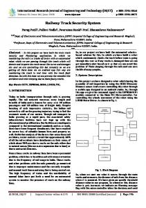
The system proposed in this paper utilizes four major components: The sensors, Controller, GSM modem, and GPS tracking system. The block diagram of the proposed system is shown in fig. 2. Micro Electro Mechanical System (Accelerometer) sensor (ADIS16220) is used for measuring the vibration. The ADIS16220 is a wide-bandwidth, digital vibration sensor collects data autonomously and makes it
Fig. 2. Block diagram of proposed system
The displacement in z-axis, the capacitance becomes ª ε l (t - z) º C (t ) = 12 « o a a (3) » d ¬ ¼ Where a-is a vertical displacement ‘z’ is a function of applied acceleration. z=
ma 24EI
= 3
maL3 24EI
(4)
L The relative capacitance change with respective to ‘a’ is
252 there is no coverage in those areas. Whenever signal is not present or the signal level is less than that of the required level FTMS automatically identified and change the operation based on the algorithm developed for data processing given in table 1.
ª §§ 3 · · ·º § « ¨ ¨ ε o l a ¨ t a − maL ¸ ¸ ¸» ¨ 24 EI ¸¹ ¸¹ ¸» ∂C ∂ « ¨¨ ¨© © ¸» = «16 ∂a ∂a « ¨ d ¸» ¸» « ¨¨ ¸ ¹»¼ ¬« ©
=
2ε o l a mL 3 3 dEI
TABLE I Status of GSM and GPS
(5)
A GSM Modem is a wireless modem that works with a GSM wireless network to transfer data. The measured signal from the Accelerometer sensor is passed through GSM base station transmitter with operating frequency of 1.8 GHz and belonging to the Vodafone network. This was done with a GSM modem TM-S3 combined with a GPS receiver TML-10 (SIMCON 900A) to determine the location of vibration. The measuring equipment was installed in a train and the antenna with a length of 1.5meters was also installed on the train. The whole system is interfaced along with a signal processing system. The train moved with starting from low to high speed, and pass through different places like forest, tunnels etc. The controller always watches the level of downlink signal, which is received by the system. The axel box and bogie contains the lateral and vertical vibration sensor arrangement is shown in fig. 2. The Accelerometer vibration sensor is used to estimate the lowest frequency from 0.1 Hz with the amplitude of 100mv. The signal acquired from the sensor is amplified and passed to analog to digital converter (ADC) and the output is give to the micro controller. The vibration produced by the track is proportional to the speed of the train. So that different speed signal was measured and the normalized value stored in the memory. The signal which is measured from the sensor is rearranged according to the speed and location measured from the GPS. The rearranged data were compared with the predefined data and the irregularity with the specified location is send through GSM to the central control office. The central office could receive and monitor the irregularities present in the entire track easily. The measured system was installed in a super fast train with the speed of 100 km/h. The system is more robust to external loading and hence little irregularity was easily observed. III.
PROBLEMS IN TRACKING
The train when passing through the tunnel or hill areas, the communication channel of GSM will disappear and when we lose line of sight in tunnels, the satellite link also gets affected. So we cannot transmit location of vibration. Therefore this problem carefully studied for continue to work the system properly. Here we first evaluate the GSM coverage problem and then GPS. A. GSM Coverage Problem The train when moving through hill areas or the tunnels,
Different types of solutions are there for GSM coverage. But in this paper we are not using any external system so the cost of the proposed system will be reduced. FTMS has intelligence to operate the system properly. It always watch the signal level of GSM and if it is in the required level it will send the GPS coordinates if any vibration is present otherwise it will store the coordinates in the memory. B. GPS Coverage Problem The controller always monitors the signal level of GSM and GPS. Whenever there is a vibration immediately it will send the GPS coordinates via GSM. In case GSM signal is not present, then FTMS store the GPS coordinates and it will always watch the GSM signal level for transferring the coordinates. Suppose GPS signal is not present or the level of the signal is less than the required level that time the controller store the current GPS coordinates and switch ON the proximity sensor immediately. The proximity sensor is used to calculate the distance, D travelled by the train. D = nd (6) Where D is the distance travelled by the train, d is the wheel diameter where the proximity is mounted (already been programmed), and n is the number of pulses generated by the proximity. Subsequently, through a simple calculation we can identify the place of vibration. Now if any vibration is present in the absence of GPS signal at that time FTMS send the new location of vibration (LOV) as
LOVnew = Latitudeold + D
(7)
For example D=2km, at that time latitude old already we know, from there take 2km again for finding the location of vibration. We may conclude that the solution presented is simple and of low cost, when compared with other previously described systems used for getting GPS or GSM signals [10].
253 IV.
FUZZY LOGIC CONTROLLER
The mechanism of a fuzzy logic based FTMS is illustrated in fig 3.The fuzzy controller performs the following steps on the input signal: 1) measure the input values from the accelerometers and assign variables. 2) performs a scale mapping on that input variables and convert the input variables into corresponding universe of discourse 3) fuzzifier performs the fuzzification function, ie:convert the input data into suitable linguistic values. The values can be viewed as labels of fuzzy sets.
The irregularities present in the axel box mounted MEMS, presents output variations greater than that of normal signal. The specification of the rules of the fuzzy logic controller depends on the designer knowledge about the vertical and lateral track vibration of both axel and bogie. The rule base for two different speeds (0-50 and 51-100 km) of axel box and bogie are given in table II and III respectively. The rules of the fuzzy controller obey the following rule: 1) Both displacement and distance of the system measurement produces considerable irregularity. If displacement (Ka or Kb)=high, and distance (D)=high, then voltage of both bogie and axel boxes are Very high. 2) The signal level of vertical irregularity is higher than that of lateral irregularity. For Vertical bogie, If displacement (Ka or Kb) =medium, and distance=medium, then voltage of bogie is small.
Fig. 3. Proposed Fuzzy Controller
4) Inference engine determine a mapping the input signal into output fuzzy set using fuzzy reasoning techniques. 5) The defuzzier perform scale mapping by using max criterion, or mean of maximum method.
Fig. 5. Membership function (a) lateral amplitude of bogie (b) lateral amplitude of axel
A. Membership Function Fuzzy logic controller has three input variables and two output variables. The input variables are: irregularities, displacement (Kb for Bogie and Ka for Axel box) and distance D.
Fig. 4. Membership function (a)Displacement (b)Distance
The output variables are voltages (VB for Bogie and VA for Axel box) measured in both lateral (La & Lb) and vertically (Va and Vb) mounted boxes. The membership function for displacement and distance are LOW, MEDIUM, HIGH as shown in fig 4(a) and (b) respectively. The membership function for output voltages are: Normal (N), Small(S), High (H), Very High (VH). The membership function of lateral and vertical amplitude of both axel and bogie are shown in fig 5 and 6 respectively.
Fig. 6. Membership function (a) vertical amplitude of Axel (b) vertical amplitude of bogie
For Vertical axel, If displacement (Ka or Kb) =medium, and distance=medium, then voltage of bogie is high. For Vertical axel, If displacement (Ka or Kb) =medium, and distance=medium, then voltage of bogie is high.
254 1) Rule Base for Bogie Lateral: If the vehicle runs normal driving condition the voltage is normal. If there is an irregularity present then rule is If Input=Lateral and Kb= Low and D=Low or Medium, then VB=Normal. If Input=Lateral and Kb and D=High or medium, then VB= High. If Input=Lateral and Kb =High, and D=High, then VB=Very High. TABLE II Speed from 0-50km for (a)Axel box (b) Bogie
Rule Base for Bogie Vertical :If the vehicle runs normal driving condition the voltage is Normal. If there is an irregularity present then rule is If Input=Vertical and Kb= Low and D=Low, then VB=Normal. If Input=Vertical and Kb =medium and D=medium, then VB= Small. If Input=Vertical and Kb =High, and D=High, then VB=Very High. 3) Rule Base for Ax-el vertical: If the vehicle runs normal driving condition the voltage is Normal. If there is an irregularity present then rule is If Input=Vertical and Kb =High or D=High or Medium, then VA= High. If Input=Vertical and Kb =High, and D=High, then VA=Very High. 2)
V.
SIMULATION RESULTS
A. Track Irregularities in Axel-Box Accelerometer The irregularities present in axel-box laterally mounted Accelerometer are illustrated with two different speed scenario is shown in fig. 7.
1) Rule Base for axel lateral: If the vehicle runs normal driving condition the voltage is Normal. If there is an irregularity present then rule is
(a)
TABLE III Speed from 50-100km for (a)Axel box (b) Bogie
(b) Fig. 7. Lateral irregularity for axel box Accelerometer (a) 5-50 Km (b) 51-100 Km
The amplitude of the vibration signal is higher than that of the normal signal because in the vibration location the track is easily deformed than the other location of the track under dynamic condition.
(a)
If Input=Lateral and Kb= Low and D=Low or Medium, then VA=Normal. If Input=Lateral and Kb =High, and D=High, then VA=Very High.
(b) Fig. 8. Vertical irregularity for axel box Accelerometer (a) 5-50 Km (b) 51-100 Km
255 A significant lateral track irregularity is clearly observed in two different scenarios at 900m are shown in fig. 7(a) & (b). The irregularities present in vertically mounted Accelerometer for two different speed scenarios are illustrated in fig. 8. It is clearly observed that vertical track irregularity is present in both the speed scenarios. The signal level of vertical irregularity is higher than that of lateral irregularity. The controller sends both the vertical and lateral location of vibration to the central office. The central office process the information sends by the train controller and an alert message will be displayed and all the information is stored in the data base. B. Track Irregularities in Bogie-Mounted Accelerometer The irregularities present in lateral bogie mounted Accelerometer are illustrated in fig. 9.
in fig. 10. A suspension system is present between the axel-box and bogie so that the vertical motion of bogie and the axel-box irregularities are almost equal in all the speed scenarios. VI.
CONCLUSION
A new method is proposed to estimate lateral and vertical irregularities using accelerometer and the signal from axel box and bogie of the train are processed by a fuzzy controller. The proposed method has the ability to find exact location of vibration. Here two different speed scenarios are studied for lateral and vertical measurement. The Accelerometer are producing accurate displacement in the entire speed scenario than other conventional methods. In the case of vertical track irregularity, the bogie mounded accelerometer is better than axel box accelerometer in the speed scenario 51-100 Km. Even though the axel box follows the irregularity than the bogie. FTMS automatically stores the coordinates when the GSM signal is absent. Suppose absence of GPS signal the signal calculate the LOV and send to the central office. The system updates the irregularity simultaneously and the problem can be easily rectified. We believe that the proposed system is much suitable for developing countries REFERENCES
(a)
(b) Fig. 9. Lateral irregularity for bogie mounted Accelerometer (a) 5-50 Km (b) 51-100 Km
(a)
Fig. 10. Vertical irregularity for bogie mounted Accelerometer (a) 5-50 Km (b) 51-100 Km
The lateral irregularities of both the axel-mounted and bogie mounted are almost equal because there is no suspension between both of them. So the lateral motion of axel-box closely follows the bogie. A significant lateral irregularity is clearly observed at 900m in both the speed scenario. The estimated track irregularities present in vertical bogie mounted Accelerometer for different speed scenario is shown
[1]
Ping Li and Roger M Goodall, “Model Based Approach to Railway Vehicle Fault Detection and Isolation”, Electronic Systems and Control Division Research, 2003. [2] Ping Li and Roger Goodall, “Model-Based Condition Monitoring for Railway Vehicle Systems”, Control 2004, University of Bath, UK, September 2004. [3] Christopher P. Ward, Roger M. Goodall, Roger Dixon, “Contact Force Estimation in the Railway Vehicle Wheel-Rail Interface” The 18th IFAC World Congress Milano (Italy), August 28 - September 2, 2011. [4] G.M. Shafiullah, Scott Simson, Adam Thompson, Peter J Wolfs2,Shawkat Ali,” Forecasting Vertical Acceleration of Railway Wagons - A comparative study”, International Conference on Data Mining, Las Vegas, USA, pp. 137-143, 14-17th July 2008. [5] Theodore L. Beach, and Paul M. Kintner,”Development and Use of a GPS Ionospheric Scintillation Monitor”. IEEE Transactions On Geoscience And Remote Sensing, Volume, 39, No. 5, May 2001. [6] Santiago Alban, Dennis M. Akos, Stephen M. Rock,” Performance Analysis and Architectures for INS-Aided GPS Tracking Loops”, ION National Technical Meeting. Anaheim, 2003. [7] S.C. van der Spek & C.M. van Langelaar, “Using Gps-Tracking Technology for Urban Design Interventions”, 28th Urban Data Management Symposium (UDMS 2011), Netherlands, 2011. [8] Guy Charles, Roger Dixon, Roger Goodall, “Condition Monitoring Approaches To Estimating Wheel-Rail Profile”, Proceedings of the UKACC Control Conference, Manchester, 2008 [9] G. J. Stein, R. Chmúrny, V. Rosík, “Compact Vibration Measuring System for in-vehicle Applications”, Measurement Science Review, Volume, 11, No. 5, 2011. [10] Robert P. Leland, “Adaptive Control of a Accelerometer Gyroscope Using Lyapunov Methods”, IEEE Transactions On Control Systems Technology, Volume, 14, NO. 2, march 2006. [11] Andre Augusto Ferreira, Jose Antenor pomilio, Giorgio Spiazzi, Leonardo de Araujo, “Energy Management Fuzzy Logic Supervisory for Electric Vehicle Power Supplies System”, IEEE Transactions on power Electronics, vol. 23, No. 1, January 2008. [12] Alexandre Ravey, Benjamin Blunier, Abdellatif Miraoui, “Control Strategies for Fuel-Cell-based hybrid Electric Vehicles: From Offline to online and Experimental results”, IEEE Transactions on Vehicular Technoloy, vol. 61, No. 6, July 2012.