Available online at www.sciencedirect.com Available online at www.sciencedirect.com
Energy Procedia
EnergyEnergy Procedia 00 (2011) 000–000 Procedia 14 (2012) 1213 – 1219 www.elsevier.com/locate/procedia
2011, 2nd International Conference on Advances in Energy Engineering (ICAEE2011)
Fuzzy Logic Controlled Microturbine Generation System for Distributed Generation Sanjeev K Nayak, a* D N Gaonkar,b R Shivarudraswamyc Department of Electrical and Electronics Engineering, National Institute of Technology Karnataka Surathkal Mangalore 575025 Karnataka INDIA
Abstract The microturbine based Distributed Generation (DG) system are becoming the popular source of power industries due to their fuel flexibility, reliability and power quality. The microturbine generation (MTG) system is a complicated thermodynamic electromechanical system with a high speed of rotation, frequency conversion and its control strategy. In spite of several techniques to control high speed of microturbine is not accurate and reliable due to their anti-interference problem. To resolve the anti-interfacing problem, this paper investigates the fuzzy logic based speed governor for a MTG system as an alternative to nominal PI or lead-lag based controller. The development of fuzzy logic based speed governor includes input and output membership function with their respective members. The load variation on MTG system is performed using conventional and fuzzy logic controller, implemented in Matlab/simulink and results are compared with each other. The simulation result shows that, the performance improvement of fuzzy logic governor over a nominal governor based MTG system.
© 2011 Published by Elsevier Ltd. Selection and/or peer-review under responsibility of the organizing committee © 2011 Published by Elsevier Ltd. Selection and/or peer-review under responsibility of [name organizer] of 2nd International Conference on Advances in Energy Engineering (ICAEE). Open access under CC BY-NC-ND license. Keywords; Microturbine PMSM, Power Converter, Fuzzy logic.
1. Introduction Distributed Generation (DG) is predicted to play an increasing attention in the electric power system of the near future. DG is limited size of generation (25kW to 1MW) and interconnected at the substation, distribution feeders or consumer load levels [1]. The microturbine generation (MTG) system is a typical and practical system of DG source, because of its small scale generation with fuel flexibility, reliability
* Corresponding author. Tel.: +91-824-2474000, 4023; fax: +91-824-2474033. E-mail address:
[email protected] or
[email protected]
1876-6102 © 2011 Published by Elsevier Ltd. Selection and/or peer-review under responsibility of the organizing committee of 2nd International Conference on Advances in Energy Engineering (ICAEE). Open access under CC BY-NC-ND license. doi:10.1016/j.egypro.2011.12.887
1214 2
K Nayak et al.\ / Energy Procedia 14 Procedia (2012) 1213 – 1219000–000 Sanjeev K Nayak, Sanjeev D N Gaonkar, R Shivarudraswamy / Energy 00 (2011)
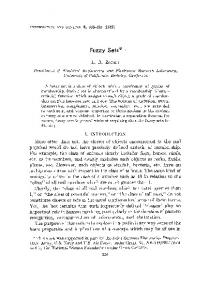
and power quality. It has been applied in various fields, such as peak power saving, co-generation, remote and premium power applications [2]. The MTG system composed of microturbine as a prime mover, permanent magnet synchronous machine (PMSM), power interfacing circuit for frequency conversion between generation and load. A microturbine is thermodynamically complex mechanical system cannot be modelled accurately and it is difficult to control the speed [2]. A microturbine is integrated with PMSM produces high frequency AC power, where the operating speed ranges generally between 50,000 to 120,000 rpm. The power produced at the generator is around 1 k to 2 kHz of frequency, this high frequency AC power is converted to DC then inverted back to 50 or 60Hz AC power using suitable converter and inverter [3]. The nonlinear controlled methods based on model cannot solves the various control problem on MTG system, some advance control methodas have been applied such as incremental fuzzy PI controller, fuzzy PID controller and neural network controllers. Controlled algorithm based on fuzzy logic have been implemented in many processes the application of such control techniques has been motivated by the following reasons, 1) it improves the robustness over a conventional linear control algorithm, 2) Simplified control design for difficult system model 3) Simplified implementation[4]. This paper presents a fuzzy logic controlled speed governor in place of conventional transfer function governor of a microturbine. The load variation on the MTG system is made to obtain the performance of microturbine used as MTG system. 1.1 Microturbine Microturbines are smaller version of heavy duty gas turbines compact in size and components like compressor, heat exchanger, burner and turbine. Basically there are two types of microturbines, classified based on construction and location of its components. One is a high speed single shaft design with compressor and the turbines are mounted on the same shaft usually the PMSM is use to generate the electrical power. Another is split shaft design that uses a power turbine rotating at 3600 rpm and a conventional generator (usually induction generator or synchronous generator) connected via a gearbox [6]. The microturbine system presented in this paper is based on gas turbine model presented by W I Rowen[5] which was successfully adopter as microturbine generation(MTG) system by Huang Wei[6] connected in parallel to the microgrid, and used as DG system by Gaonkar[7] and Guda S R[8] in isolated mode. The turbine model was proposed by W I Rowen[5] is to be adopted as single shaft microturbine with fuzzy logic speed governor implemented in MATLAB/Simulink is shown in Fig.1, and the same is used as prime mover for the MTG with PMSM and power electronics circuit interfacing system shown in Fig.2. +
Tempreture controller
Tr
Reference Temp f1(u)
+ 3.3s+1 0.5s
+ Ref Speed(pu)
+
G5 1+sT5
+ G4 1+sT4
-
K1
L O W
-
X
Exhaust system
+
K3
+
K2
100 s
Speed Governor 0.01
+
Acceleration controller -
du dt
Rotor Speed
f2(u)
-
0.8
0.23 du dt
+
1 JT Rotor Inertia
e-sT
Fuel & Combustion G2 1+sT2
G1 1+sT1
+
f3(u)
Pulse
Microturbine Speed
Torque
Voltage regulator Vabc
AC
PMSM
DC Filter
C
e-sT
DC G3 1+sT3
Diode rectifier
AC Diode/IGBT
Turbine dynamics +
Fig.1. Fuzzy logic controlled microturbine
f4(u)
Resistive load
Fig.2 Fuzzy logic controlled MTG system
The linear pattern is utilizes as generator model applicable for transient analysis and the model comprises temperature controller, fuel control, turbine dynamics, speed governor and acceleration controller blocks [7]. The speed governor for a microturbine can be divided into droop regulation and non-drop regulation, which is utilized and designed for the purpose of adopting the requirement of different load characteristics.
1215 3
Sanjeev et al.\ / Energy Procedia 14 (2012) 1213 – 00 1219 Sanjeev K Nayak, D KN Nayak Gaonkar, R Shivarudraswamy/ Energy Procedia (2011) 000–000
Speed controller is usually modelled using lead-lag transfer function or by PID controller. In this work a fuzzy logic based governor has been used as speed and change in speed are input member ship function, regulated speed as output membership function. The membership function can adjusted so that the governor can act with droop or as isochronous governor [7][8]. The fuel flow is controlled as a function of Vce are shown in a series of blocks including the valve position and flow dynamics, the output of low value selector (represented by Min in MATLAB/Simulink) is the lowest of the three inputs and results in the amount of fuel to the compressor-turbine, and Vce represents the final amount of fuel demand for that particular operating point and is an input to the fuel system [6][8]. The slow dynamics performance of the MTG system is focused here based on the simplified model is built in with an assumption, i.e. MTG system is operating under normal condition by neglecting the fast dynamics of microturbine (start up, shut down, internal faults, sudden loss of power etc). In addition to that the proposed model employees per unit system to represents the microturbine as its control system with expectation of temperature, each important control block is discussed as subsection in[7] [8]. The model presented in this paper is concentrates on slow dynamics of MTG system. 1.2 Permanent Magnet Synchronous Machine (PMSM) and Power Electronics Interface Circuit. The MTG system uses high speed PMSM for conversation of mechanical energy to electrical energy. The model adopted for MTG system is, a two pole PMSM with a non-salient rotor. At 1600Hz frequency, the rated power generated by the machine is 60KW and its terminal line to line voltage is 480V. The electrical and mechanical component of the generator are represented by two second order state space models, meanwhile the DC field winding of the rotor is replaced by a permanent magnet, the main advantage of eliminating of field copper loss, a higher power density, lower rotor inertia, and roughed in construction of the rotor. The analyses of PMSM by dq0 axis for a balanced dq axis equation are shown in [12], and the parameters of high speed PMSM are as per the Table.2. The high frequency AC power generated by the PMSM is rectified to DC and then inverted back to 50 or 60Hz AC, after elimination of harmonics it is feed to the general use. The power conditioning is the critical component in a single shaft microturbine MTG system, especially in matching turbine output to the required load [7]. The power conditioning circuit consists of three phase simple diode bridge rectifier, voltage source inverter (VSI) and inductance, capacitance (LC) filter. The IGBT inverter uses pulse width modulation (PWM) at carrier frequency of 2000 Hz and sampling time of 2µs, the filtered DC voltage is applied to an IGBT two level inverter generating 50Hz, and control scheme are regulated at 480 V rms. PMSM Parameter Number of poles
P=2
Maximum speed
Nmax =100krpm
Moment of inertia
J=7e-4kgm2
Stator resistance
Rs=0.08
d & q inductance
Ld=Lq=286µH
Rated power
Pn = 30kW Table 2. PMSM parameters
abc to dq0
Vabc
Selector Vdc, ref, pu 0 0 Vq, ref Sin_ Cos
+ Vd, ref
PI
dq0 to abc
To PWM
Discrete virtual PLL
Fig.3 Voltage control scheme of VSI
The load voltage is regulated at 1 pu by a PI voltage regulator using abc_to_dq and dq_to _abc transformation. The output of voltage regulator is a vector containing the three modulating signals used by the PWM generator to generate six IGBT pulses. The discrete three phase PWM pulse generator is available in the discrete block library of Matlab/Simulink.
1216 4
K Nayak et al.\ / Energy Procedia 14 Procedia (2012) 1213 – 1219000–000 Sanjeev K Nayak, Sanjeev D N Gaonkar, R Shivarudraswamy / Energy 00 (2011)
2. Fuzzy logic Fuzzy logic controller is rule based controller where a set of rules represents a control decision mechanism to correct the effect of certain cause used for generation systems. In fuzzy logic, the linguistic variables are expressed by fuzzy sets defined on their respective universe discourse, to overcome the difficulties of soft controlling fuzzy logic found to be effective alternating to conventional control techniques[9]-[10]. The configuration of fuzzy logic based system into four parts they are, • Fuzzification, Knowledge Base, Interface Mechanism and Defuzzification. The lead lag transfer function compensator is replaced by the equivalent fuzzy logic based speed governor, the design of PI-like fuzzy knowledge base controller works on the area control error (ACE) and change in area control error (∆ACE) is considered as input to the fuzzy logic controller. For the automatic generation control problem the input to fuzzy controller for ith area at a particular instant are ACEi(t) and UACEi(t). The input and output are transformed into linguistic variables as VHS: Very High Speed, HS: High Speed, NC: No Change, NS: Normal Speed, LS: Low Speed, VLS: Very Low Speed, LN: Large Negative, N: Negative, P: Positive, LP: Large Positive, VL: Very Low, L: Low, Z: Zero, H: High, VH: Very High- respectively. All the variables of ACE, ∆ACE and ∆U are considered in a symmetrical triangular membership function. The membership function of ACE over the operating range of minimum and maximum values of ACE is shown in Fig.4 (a)(b) and (c). The membership function would perform a mapping from the crisp values to a fuzzified value, One such particular crisp input ACE is converted to fuzzified value i.e. 0.8/VHS + 0.2/HS where 0.8 and 0.2 are membership grade membership function. Speed
VHS HS NS LS VLS 1 0.8
1
0.5
VL L Z
H
VH
0.5
1
LN N NC
P
LP
0.5
0.2 0
0
Fig.4 a) Speed
VL
L
Z
H
VH
VLS
LN
LN
LN
N
NC
LS
LN
LN
N
NC
P
Speed
NS
LN
N
NC
P
LP
HS
N
NC
P
LP
LP
VHS
NC
P
LP
LP
LP
0
b) Change in speed
c) Reg, speed
Table. 2 Fuzzy logic table
Corresponding to the linguistics variables VHS and HS in fuzzy system a membership grades are zero for all other linguistic values except VHS and HS. Here the crisp value input to the system will be converted to fuzzified value considering several membership grades corresponding to each linguistic variable. Same way the other input of ∆ACE and ∆U are fuzzified. The output of the inference mechanism is a fuzzy value, and hence it is necessary to convert the fuzzy value to (crisp) real value sine, the physical process can’t deal with fuzzy values. This operation which is inversely fuzzified is known as defuzzification. The well known centre of defuzzification method has been used for its simplicity. The major drawback of Mean of Maximum (MOM) method is that it does not use all the information converted by the fuzzy command and hence it becomes difficult in generating commands that run the system smoothly. Σ μ j * Uj Σ ( Membership I P *Output correspond ing I P ) ΔU = ΔU = ∑ ( Membership of I P ) Σμj ∆U is determined using the centre of gravity method µj is the membership value of the lingivustic variables recommending the fuzzy control action, Uj is the precise numerical value corresponding to the fuzzy control action. The ∆U obtained from (9) is added with the existing previous signal to obtain the actual output signal U which is given to the microturbine [11].
1217 5
SanjeevDKNNayak et al.\ / Energy Procedia 14 (2012) 1213 – 00 1219 Sanjeev K Nayak, Gaonkar, R Shivarudraswamy/ Energy Procedia (2011) 000–000
3. Results and discussion The MTG system is simulated using both conventional and fuzzy logic governor microturbine. Initially the MTG system is driving a 10kW, 380 volts electrical load. Due to the small inertia and damping in the microturbine without considering the complex and non-linear start-up processes, the stable operation cannot be considered for first 25 seconds. Based on this consideration dynamic simulations have been performed to evaluate the response of the MTG system. Initially the fuel demand is 0.58 pu for 10kW load. At t=30 secs the load is increased to 10kW and the fuel demand is increased to 0.75 pu. Again at t=60 secs a 10 kW load is increased and the fuel demand is also increase as shown in Fig.5 (a). The shaft torque varies as the load varies on MTG system, this variation in the torque at interval of t=30, 60 and 90 secs is shown in Fig.5 (b). The speed and torque are inversely proportional to each other, hence the decreasing and increasing in the speed at t=30, 90 secs and t= 90 secs respectively as shown in Fig.5(c). The power developed in the turbine is also proportional to the demand power, the turbine power varies as the demand power varies as shown in Fig.5 (d).
0.7 Conventional governor Fuzzy logic governor
0.6 30
40
50
(a)
60
Time in sec
70
80
300 200 100
Conventional governor Fuzzy logic governor
0
90
30
40
50
80
Time in sec
90
100
0.7 0.6 Conventional governor Fuzzy logic governor 30
40
50
60
70
Time in sec
80
DC link voltage in volts
0.975 0.97 0.965
400
380 Conventional governor Fuzzy logic governor 29
29.5
60
70
Time in sec
Conventional governor Fuzzy logic governor 80 90
30
30.5
31
31.5
Time in sec
32
32.5
-200
-400
Conventional governor Fuzzy logic governor 40
50
(d)
60
70
Time in sec
60.01
60.02
80
90
100
60.03
60.04
Time in sec
Conventional governor Fuzzy logic governor 60.05 60.06 60.07
40
380 370 360
Transfer function governor Fuzzy logic governor 59
59.5
60
60.5
61
Time in sec
61.5
62
30 20 10 0 -10 -20 Conventional governor Fuzzy logic governor
-30
62.5
-40
30
40
50
60
Time in sec
70
80
90
100
(k) 50
400
40
Load current in ampres
DC link voltage in volts
Turbine power in pu
0.6 0.5
60
(j)
0.9
0.7
Conventional governor Fuzzy logic governor 80 90
0
(g)
0.8
Time in sec
70
50
390
350
100
60
200
400
(c)
30
50
(f)
0.98
50
40
400
(b)
40
30
(i)
420
360
90
0.985
30
0
-200
-400
Load voltage in volts
DC link voltage in volts
0.8
0.5
Turbine speed
70
440
0.9
0.96
60
200
(e)
1
Shaft torque
400
Load current in am pres
Fuel demand
0.8
400
Load voltage in volts
DC link voltage in volts
500
0.9
390 380 Conventional governor Fuzzy logic governor
370 88
89
90
(h)
91
Time in sec
92
93
30 20 10 0 -10 -20 Conventional governor Fuzzy logic governor
-30 -40
59.9
59.95
60
(l)
Time in sec
60.05
60.1
60.15
Fig. 5(a) Fuel demand in pu, (b) Shaft torque in pu, (c) Turbine speed in pu, (d) Turbine power in pu, (e) DC link voltage in volts, (f) DC link voltage at t=30sec,(g) DC link voltage at 60sec, (h) DC link voltage at 90sec,(i) Load voltage Vac (j) Sinusoidal voltage in volts, (k) Load current in amps, (l) Variation in load current.
1218 6
K Nayak et al.\ / Energy Procedia 14 Procedia (2012) 1213 – 1219000–000 Sanjeev K Nayak, Sanjeev D N Gaonkar, R Shivarudraswamy / Energy 00 (2011)
The DC link voltage Vdc, varies as the load varies at internal of t= 30, 60 and 90 secs on the MTG system is shown in Fig.5 (e). The variation of DC link voltage at interval of t=30, 60 and 90 secs and comparison of governor performance are as shown in Figs.5(f),5(g) and 5(h) respectively. The variation of load AC voltage Vac with variation of load on the DG system is shown in Fig.5 (j) and the sinusoidal voltage is shown in Fig.5(j). The load current Iac is shown in Fig.5(k) and sinusoidal current waveform is shown in Fig.5(l). During every interval of load variation, there is a variation in demand power, i.e. at t= 30, 60 and 90 secs the transients are formed in case of conventional govern but are minimized in fuzzy logic governor. These transients are causing an effect of power quality in the electrical system. Thus these are minimized by using fuzzy logic based governor and power quality can be improved. Conclusion This paper replaces the conventional lead-lag governor by fuzzy logic governed for a microturbine and compares the performance of those two governors and conformed that the fuzzy logic governor is having less transients on each load variation on the microturbine based MTG system. Then fuzzy controlled microturbine is connected to MTG system via PMSM and power interfacing circuit to the load. The performance of fuzzy logic based governed MTG system is obtained and there is an improvement of the fuzzy controller is high robust against the interference. It is easy for non mathematical and engineering implementation. The simulation results are obtained in MATLAB/Simulink environment and shown that fuzzy controlled microturbine can ensure the desirable dynamic response of the MTG system and has ability of the anti-interfacing as a distributed generation system. The use of fuzzy logic based controller in the microturbine will have the positive impact on power quality in the electrical distribution system. References [1]
P. P. Barker, and R. W. de Mello, Determining the impact of distributed generation on power systems: Part 1-
Radial Distribution systems,” in Proc. IEEE Power Eng. Society. Summer Meeting, vol. 3, 2000, pp.1645-1656. [2]
Shijie Yan and Xu Wang “Fuzzy Controlled with Tracking Differentiator for Microturbine” Sixth
international conference on fuzzy systems and Knowledge Discovery,FSKD-2009 Tianjin,14th -16th August 2009, pp. 97–101. [3]
A. Al-Hinai and A. Feliachi, “Dynamic model of microturbine used as a distributed generation” in Proc 34th
South Eastern Symposiums on system theory, Huntsville, Alabama, 2002,pp.209-213. [4]
Jenica Ileana Corcau and Eleonor Stoenescu “Fuzzy logic controlled as power system stabilizer”
International Journal of Circuits, System and Signal Processing, Vol.1, Issue.3, 2007, pp.266-273. [5]
W. I. Rowen, “Simplified Mathematical Representations of Heavy Duty Gas Turbines,” Journal of
Engineering for Power, Trans. ASME, vol. 105, no. 4, pp. 865-869, Oct, 1983. [6]
Hung Wei, Wu Ziping, Niu Ming, Zhang Jianhua, Guo Yuanbo and Wu Chong “Dynamic Modelling and
Simulation of Microturbine Generation System for the parallel operation of microgrid” International Conference on Sustainable Power Generation and Supply,2009 SUPERGEN-09, Nanjing, 6th -7th April 2009, pp.1-8. [7]
D. N. Gaonkar and R N Patel “Modeling and Simulation of Microturbine Based Distributed Generation
System” IEEE Power India Conference 2006, New Delhi, 5th June 2006. pp.05. [8]
S. R. Guda. C .Wang and M H. Neherir, “Modeling of Microturbine Power Generation Systems” Electric
Power Components and systems,1532-5016, Vol.34, Issue.9,pp.1027-1041,2006. [9]
U. Yolac and T Yalcinoz “Comparison of fuzzy logic and PID controller for TCSC using MatLab” 39th IEEE
International Conference on Power Engineering, Vol.1,2004,pp.438-442. [10]
B Anand and Ebenezer Jeyakumar “Fuzzy logic based load frequency control of hydro thermal system with
non-linearity” International Journals of Electrical and Power Engineering, Vol.3,Issue.2,2009,pp.112-118. [11]
Shijie Yan and Xu Wang “Active Disturbance Rejection Fuzzy Control of MTG Fuel pressure” IEEE
Sanjeev Nayak et al.\ / Energy ProcediaEnergy 14 (2012) 1213 –001219 Sanjeev K Nayak, D NKGaonkar, R Shivarudraswamy/ Procedia (2011) 000–000 International Conference on Mechatronics and automation, 9th -12th August 2009 Changchum, China. [12]
J. B Ahn, Y. H. jeong, D.H. Kang and J.H.Park “Development of High Speed PMSM for Distributed
Generation Using Microturbine” 30th IEEE Annual Conference on Industrial Electronics Society, November 2-6,2004,Busan, Korea.
1219 7