loads, triac based controllers for heating applications, or some combination of the two. These loads draw currents, which have high harmonic content and poor.
Journal of Computer Science 3 (2): 76-80, 2007 ISSN 1549-3636 © 2007 Science Publications
Fuzzy Logic Controller Based Three-phase Shunt Active Filter for Line Harmonics Reduction 1
C.Sharmeela, 2M.R.Mohan, 2G.Uma, 2J.Baskaran A.C.College of Technology, Anna University, 2College of Engineering, Guindy, 2 Anna University, Chennai-600 025, India
1
Abstract: Harmonic distortion is a form of electrical noise. It is a superposition of signals, which are of multiples of fundamental frequency. Proliferation of large power electronic systems results in increased harmonic distortion. Harmonic distortion results in reduction of power quality and system stability. This paper presents fuzzy control applicable for active power filter for three-phase systems, which are comprised of nonlinear loads. The active filter is based on a three-phase inverter with six controllable switches. The AC side of the inverter is connected in parallel with the other nonlinear loads through a filter inductance. The DC side of the inverter is connected to a filter capacitor. The Fuzzy Controller (FC) is used to shape the current through the filter inductor such that the line current is in phase with and of the same shape as the input voltage. The results of the computer simulation prove that the injected harmonics are greatly reduced, system efficiency and power factor are improved. Key words: Fuzzy logic controller, shunt active filter, line harmonics reduction INTRODUCTION
X5
vs
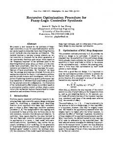
This paper is motivated by systems which contain multiple non-linear loads, whether they may be controlled and uncontrolled rectifiers for dc based loads, triac based controllers for heating applications, or some combination of the two. These loads draw currents, which have high harmonic content and poor power factor. The use of active systems for compensating harmonic distortion and reactive power supply in the electrical networks, both at user level or at higher voltage level is preferred than the classical passive compensating methods. Active filters permit the control and the compensation of the distorted line currents adapting themselves to the load changes and to changing in working frequency[1,2]. The line harmonics reduction using ANN based controller is discussed in[3]. The representative load used in this paper is an controlled rectifier as shown in the Fig. 1.
0
source voltage
T1
T6
T4
L1
T5
T3
T2
controlled rectifier
2
2 0
2
0
0
L2 L3 1
2
1
2
S6
0 1
S4
2
0
1
2
1
2
filter inductor
filter capacitor
2
1
0
1
2
1
S5 1
S3 1
L1
1
2
1
S1
S2 2
active filter
Fig. 1: The Three phase system considered in this work circuit is presented. Finally, typical waveforms are given to validate the operation of the active filter
The active filter used to compensate for the nonlinear load is a three-phase inverter. The Shunt Active Filter (SAF) is controlled by a ProportionalIntegral (PI) controller and FC. They are used to shape the line current to be in phase and of the same shape as the supply voltage. The three-phase SAF configuration is simulated using MATLAB/SIMULINK. The effect of SAF on harmonic reduction is also presented. This paper first discusses the sliding mode control concepts including inverter model for the active filter, which addresses the design of power circuit as well as the controller. Then the design of power circuit and control
THE INVERTER MODEL The voltage source inverter used as an active filter is shown in Fig. 2. The switches shown support unipolar voltage, bipolar current and are operated in a manner which forces the inductor current, iL, to follow whatever shape that is necessary such that the total load current drawn by the filter and nonlinear loads is of the correct magnitude and of the same shape as the input voltage. The nominal capacitor voltage must be larger than the peak of the ac source.
Corresponding Author: C. Sharmeela, A.C. College of Technology, Anna University, Chennai-600025, India
76
J. Computer Sci., 3 (2): 76-80, 2007 The tracking of the system on the sliding surface is governed by satisfying the natural control law,
S2
ss ≤ 0
(6) The equivalent control can be calculated from s . The expression, s for the active filter is obtained by s x = ilinex − kVxn
D2 Vln
L 2C
( = (i
VC 2
load x
S1
D1 2C
VC 2
Vxn L
2L Vc
(8) This expression is used for the filter design and to maintain the stability of the filter. DESIGN OF THE POWER CIRCUIT The fundamental design of the power circuit involves selecting the value of filter capacitor, filter inductance and the nominal value of the capacitor voltage. The selection of controllable switches to support unipolar voltage and bipolar current is implemented by a transistor with an anti-parallel diode. The maximum voltage supported by the controllable switches is the maximum DC bus voltage. The nominal value of Vc must be at least twice the peak of the line-neutral voltage in order to assure control over the slope of the filter inductor current at all times. The size of the filter capacitor is based on the allowable voltage ripple during each cycle of operation. The capacitor voltage with respect to time is calculated by integrating Eq. (2). ωt 1 i i i Vc = Vo − ua La + ub Lb + uc Lc d (ωt ) 2ω 0 C C C (9) Eq.(9) is used to determine the required capacitor size for an acceptable voltage ripple. The current, which is supported by each switch, is the maximum inductor current. The filter inductor current is given by iL = iline − iloads P iline = 2 loads sin ωt Vrms (10)
(1) The inductor current is always shaped as long as Vc/2> Vln. The expression for the capacitor voltage taking into account the ripple due to the compensating current is derived as
dvc 1 i i i = − u a La + ub Lb + uc Lc dt 2 C C C
(2) Where ua, ub and uc are the independent controls for phases a, b, and c, respectively, and iLa, iLb and iLc are the compensating currents for phases a, b, and c, respectively. The filter in terms of three first-order independent systems is expressed as
ilinex = iload x + icomp x
Vxn V + u x c dt L 2L
(3) Where x denotes the phase. Applying, sliding mode control theory to the active power filter, it is necessary that the system should follow the defined sliding surfaces or trajectories. Therefore, the combined nonlinear load and active power filter should present a unity power factor load to the utility supply. Thus, the trajectories for the line currents is defined as
DESIGN OF THE CONTROLLER SCHEME FOR SAF In the open loop, the switches S1 - S6 are operated at 180º mode of conduction for the three-phase voltage source inverter. In this case the current injected by the filter is independent of distorted source current. The source current of the three-phase system supplying a nonlinear load is not a pure sine wave. In order to shape the source current to be sinusoidal, a closed loop
iref x = k (Vxn )
(4) Where k is the scaling factor based on the power demand of the load. When the system is on the sliding surface the standard form for the surface s is written as
]
Vxn V + (u x ) c − kVxn L 2L
ueqx = kVxn − iload x −
diL Vin V = +u c dt L 2L
[
)
(7) The equivalent control is obtained by equating eq.(7) to zero.
This enables iL to be shaped as required at any point in the supply cycle[4,5]. The switching function U is defined in such a manner that U = 1, when either S1 or D1 is conducting and U = -1, when either S2 or D2 is conducting. The inductor current is given by
s x = iline x − k (Vxn ) = 0
+ icompx − kVxn
= iload x +
Fig. 2: The single-phase inverter used as an active filter
= iload x +
)
(5) 77
J. Computer Sci., 3 (2): 76-80, 2007 The closed loop controller for shunt active filter is shown in Fig. 3. It has an inner current control loop and an outer voltage control loop. The inner current control loop uses sliding mode control law to shape the line current. The outer voltage loop decides the magnitude of the reference line current (k).
control is necessary. In the closed loop control, the actual source current and the sinusoidal reference current are compared and switching pulses for switches S1 - S6 are produced.
Fig. 7: Line Current (Discontinuous Mode) using PI controller
Fig. 3: The Control scheme of the FC for the active filter
Fig. 8: Line Current (Discontinuous Mode) using Fuzzy controller Fig. 4: Line current without active filter
Fig. 9: Supply voltage
Fig. 5: Line current (Continuous Mode) using PI controller Fig. 10: Inverter capacitor voltage using PI controller
Fig. 6: Line current (Continuous Mode) using Fuzzy controller
Fig. 11: Inverter capacitor voltage using FC
78
J. Computer Sci., 3 (2): 76-80, 2007 The capacitor voltage is given to a low pass filter, which gives average capacitor voltage. This Vc is compared with nominal set point capacitor voltage. The error is processed using conventional PI and fuzzy controller. The output of the controller is the proportionality factor k. The reference line current, iline* is obtained through multiplication of k with Vs. The reference line current is compared with the actual source current. This is given to the input of the Sliding Mode Controller (SMC). The output of the SMC is given to switches S1 - S6.
output label is given in Table 1. The defuzzification stage produces the final crisp value of k. The centroid method is employed for defuzzification. SIMULATION PARAMETERS Supply = 120 Vpeak, f=50 Hz, Coupling transformer = 3:1, Controlled rectifier load with R = 6Ω, L=26.5mH. The firing angle for the ac load is set at = 30°(Continuous) and = 90°. Table 1: Fuzzy rule representation e ----------------------------------------------------------------------------Ce NB NM NS Z PS PM PB NB NB NB NB NB NM NS Z NM NB NB NB NM NS Z PS NS NB NB NM NS Z PS PM Z NB NM NS Z PS PM PB PS NM NS Z PS PM PB PB PM NS Z PS PM PB PB PB PB Z PS PM PB PB PB PB
a. Fuzzy controller: The nonlinear load variation and changes in capacitor voltage and inductor current affects the source current. The harmonics present in the source current are compensated by developing a suitable switching pattern for the active filter. The SAF controlled using PI is reported in[1]. Accordingly, PI controller is developed and simulated. The control of the distortions by proper switching is first simulated by the conventional PI controller. The PI controller settings are found to work satisfactorily only for a particular operating condition in the continuous mode. When the conventional PI controller is employed the source current shaping is achieved along with the significant amount of spikes. The PI controller setting fails to correct the source current for the discontinuous mode of the non-linear load. Therefore, a mamdani type fuzzy logic controller is proposed for multiple nonlinear loads to limit the line current distortion using three-phase active power filter. In the presence of fuzzy controller the source current shaping is achieved with negligible amount of spikes resulting in %reduction in THD. The time taken by the conventional PI controller in shaping the line current is 0.2 sec whereas with fuzzy controller it takes 0.06 sec. The fuzzy controller works satisfactorily for both continuous and discontinuous mode of operation at various operating conditions of the non-linear load. Thus, the proposed FC has better dynamic behavior than conventional PI control. It is claimed[6-8] that the fuzzy logic control yields the results, which are superior to those, obtained with the conventional controllers. In the FC, the simplicity of a PI controller is combined with the intelligence and adaptiveness of the fuzzy logic based control system. Therefore the FC is characterized as an intelligentadaptive controller.
Table 2:
Comparison for THD in continuous and modes S.No Modes of Operation THD THD Without with SAF SAF using PI 1. Continuous mode 0.3884 0.3373 2. Discontinuous mode 0.7751 1.3240
discontinuous THD with SAF using FC 0.3225 0.4143
(discontinuous), bandwidth of the low pass filter is 90 Hz and fd (decision frequency) =32 kHz RESULTS The line current without active filter is given in Fig. 4. The line current for continuous mode using PI and Fuzzy controller are given in Fig. 5 and 6, respectively. The line current for discontinuous mode using PI and Fuzzy controller are given in Fig. 7 and 8, respectively. The supply voltage of the test system is given in Fig. 9. The inverter capacitor voltage using the conventional PI controller and FC are shown in Fig. 10 and 11, respectively. The sum of active filter current and load current gives the supply current. The simulation results of Total Harmonic Distortion (THD) before and after the implementation of PI and fuzzy based shunt active filter for continuous mode and discontinuous modes of operation are shown in Table 2.
For the proposed FC, the two input signals are capacitor voltage error and change in error are properly scaled and fuzzified. Seven membership functions are used for error, change in error and also for controller output k. Linear triangular membership function is used in the design of fuzzy controller for SAF. With two input variable and each variable having seven labels there will be 49 input label pairs. A rule table relating each one of the 49 input label pairs to the respective
CONCLUSION The shunt active filter for the three-phase circuit is simulated and the THD measured verifies the reduction of harmonics in the presence of fuzzy based shunt active filter. The simulation results indicate the decrease in the current THD for SAF using FC in both modes of operation. The THD measures in the presence of a controlled shunt active filter are within the IEEE519 harmonics standards. The fuzzy control 79
J. Computer Sci., 3 (2): 76-80, 2007 demonstrates better dynamic behavior than conventional PI. The main advantages of this approach are that the inverter system can operate simultaneously as an active filter and as a compensator for unbalanced loads.
5. 6.
REFERENCES 1.
2. 3. 4.
7.
David, A.T., M.A.M. Adel and Al-Zamel, 1995. Single -phase active power filters for multiple non linear loads. IEEE Trans. on Power Electronics, 10: 263-272. Janko, N., R. Cajhen, M. Seliger and P. Jereb, 1994. Active power filter for non-linear a.c loads. IEEE Trans. on Power Electronics, 9: 92-96. Sharmeela, C., G. Uma and M.R. Mohan, 2003. Line harmonics reduction using neural based shunt active power filter. IEEE-TENCON. Kassakian, J.G., M.F. Schlect and G.C. Verghese, 1991. Principles of Power Electronics. AddisonWesley.
8.
80
Mohan, N and P. Robbins, 1989. Power electronics Converters, Applications and Design. John Wiley Publication. Akagi, H and H. Fujita, 1995. A new power line conditioner for harmonic compensation in power systems. IEEE Trans. on Power Delivery, 10: 1570-1575. Grady, W.M., M.J. Samotyj and A.H. Noyola, 1990. Survey of active power line conditioning methodologies. IEEE Trans. Power Delivery, 5: 1536-1542. Dixon et al., 1997. DC link fuzzy control for an active power filter sensing the line current only. IEEE-PESC., pp: 1109-1114.