SHORT PAPER International Journal of Recent Trends in Engineering, Vol 2, No. 7, November 2009
DSP Based Digital Controller for Shunt Active Power Filter to Improve Power Quality Ginnes K John1, Sindhu M R2, and Manjula G Nair3 1
Adi Shankara Institute of Engineering and Technology, Department of Electrical and Electronics Engineering, Kochi, India, Email:
[email protected] 2,3 Amrita School of Engineering, Amrita Vishwa Vidyapeetham, Department of Electrical and Electronics Engineering, Coimbatore,India, Emails:
[email protected],
[email protected] current – reactive component and harmonics – is to be supplied by the active filter [3]. The extraction of real component of load current can be done as follows: The load current contains fundamental component and harmonic components. Harmonic components are filtered out with the help of low pass (biquad) filter. Its output is fundamental component delayed by 90°(ie, im sin(ωt-φ90°)). At the time of negative zero crossing of the input voltage,ie.,ωt=180°, instantaneous value of fundamental component of load current is im cosφ.The magnitude of the
Abstract— The proliferation of highly sensitive power system equipments demand high quality power supplied by utility. Hence power quality has been very interesting research area for past many years. Current harmonics are one of the most significant power quality issue, which is usually resolved by using shunt passive filters or shunt active filters. In this paper ICOSφ algorithm [3] based shunt active filter is implemented in analog circuit and tested for a nonlinear load. The test results show that it can compensate for current harmonics. The algorithm was implemented digitally by dsPIC 30F 4011 microcontroller with help of MPLAB C30 Compiler.
desired source current Is ( ref ) can be expressed as the
Index Terms—Active power filter, Digital signal processor, Power quality
magnitude of real component of the fundamental load current in the respective phases. i.e. for phase a it can be written as Is ( ref ) = Re( ILa ) .
I. INTRODUCTION
T
he excessive growth in the usage of nonlinear loads such as power electronic devices, switched converters etc. has caused power quality issues like harmonic distortion in source current, low power factor and excessive neutral current. These nonlinear loads generate harmonic current to supply network and causes harmonic voltage distortion at point of common coupling (PCC). Active filters can be classified as series, shunt and hybrid filters. Series active filters help to reduce voltage harmonics, shunt active filter reduces current harmonics, whereas hybrid active filter can be used for reduction of current and voltage harmonics reduction in source side [1-2]. Since current harmonic reduction itself will reduce voltage harmonics to a great extent, shunt active filters are highly used. In this paper, ICOSφ algorithm [3] was implemented in analog circuit for harmonic reduction of nonlinear load, three phase diode bridge rectifier. Equivalent digital controller for shunt active filter was also set up for testing.
The desired (reference) source currents in the three phases are given as,
isa(ref ) = Is(ref ) ×Ua = Is(ref ) .sin ωt
isb(ref ) = Is(ref ) ×Ub = Is(ref ) .sin(ωt −1200 ) isc ( ref ) = Is ( ref ) ×Uc = Is ( ref ) .sin(ωt + 1200 ) Where, Ua, Ub and Uc are the unit amplitude templates of the phase to ground source voltages in the three phases
Ua =1.sin ωt ; Ub = 1.sin(ωt −1200 ) Uc = 1.sin(ωt +1200 )
respectively.ie,
;
The compensation currents to be injected by the shunt active filter are the difference between the actual load currents and the desired source currents.
ia(comp) =iLa − isa(ref ) ; ib(comp) =iLb −isb(ref )
ic(comp) =iLc −isc(ref ) ;
II. ICOSφ ALGORITHM
;
In ICOSφ algorithm, mains required to supply only the real component of the load current, remaining parts of load
III. ANALOG CIRCUIT IMPLEMENTATION OF SHUNT ACTIVE
Copy right credit, 1208, Sindhu M R(Corresponding author) Ginnes. K. John is with Electrical and Electronics Engineering Department, Adishankara Institute of Engineering and Technology, Kochi, Kerala.(email:
[email protected]) M. R.Sindhu is with Electrical and Electronics Engineering Department, Amrita School of Engineering, Amrita Vishwa vidypeetham Deemed University, Coimbatore.(e-mail:
[email protected]) Manjula. G. Nair is with Electrical and Electronics Engineering Department, Amrita School of Engineering, Amrita Vishwa vidypeetham Deemed University, Coimbatore.(e-mail:
[email protected])
A laboratory model of ICOSφ controller based shunt active filter was set up for testing with the nonlinear load, three phase diode bridge rectifier. A voltage source inverter assembly, which consists of a three phase IGBT based inverter along with large DC link capacitor, is used as the shunt active filter. DC link capacitor of 1650mF / 800V is used to maintain steady voltage required by the inverter. The operations in analog circuit can be explained as follows:
FILTER
92
© 2009 ACADEMY PUBLISHER
SHORT PAPER International Journal of Recent Trends in Engineering, Vol 2, No. 7, November 2009 source/load currents in a, b, c phases with diode bridge rectifier feeding resistive load.
Step 1: The source voltages, load currents and active filter injection currents are sensed with hall effect voltage and current sensors. Step 2: Detection of fundamental component of load current: Low pass filtering by using biquad filter is done to extract fundamental component of load current. The advantages of using biquad filter, rather than other low pass filters, are it is easy to design, gives unity gain and exact 90° phase shift. Step 3: Determination of real component of load current: The circuit with the comparator and monostable multivibrator 74LS123 is used for getting sharp output pulses at the negative zero crossing of the phase voltage. These pulses and output of the biquad filter are fed to a sample and hold circuit to obtain instantaneous value of fundamental component of load current at negative zero crossing of source voltage, ie., real part of load current. Step 4: Obtaining desired source current waveforms: The real component of load current is multiplied with unit sinusoidal waves to obtain desired source current waveforms, using AD 633 JN multiplier. Step 5: Derive PWM pulses to inverter: The reference compensation current is obtained by subtracting reference source current from load current. A comparator is used to compare reference compensation current and actual filter current. When reference filter current is more than actual filter current, output of the comparator is high and vice versa. The comparator is realized using LM 741. The isolation between power circuit and controller circuit is done using an optocoupler 6N136. The output pulses are amplified using transistor amplifier BC 547. A. Three phase diode bridge rectifier load
Fig. 1(b): Source current harmonic spectra Fig. 1: Experimental results with three phase diode bridge rectifier load – without shunt active filtering
Case II: with shunt active filtering: A Voltage source inverter is used as shunt active power filter which injects harmonics required by the load. Corresponding source voltage and source current waveforms and source current harmonic spectra are shown in Fig.2. It can be seen that shunt active power filter provides effective compensation. THD of source current has been reduced to around 7% from 30%.
Fig. 2(a): Source voltages and source currents in a, b, and c phases
A three phase 400V, 50Hz supply is connected to a three phase diode bridge rectifier feeding 3kW resistive load. The effectiveness of the active filter controller based on ICOSφ algorithm was tested with this load. Case I: Three phase system without shunt active filtering: A scaled down three phase supply voltage of 30V (rms) balanced voltage was applied in three phases a, b and c. The source voltage, source current waveforms and source current harmonic spectra are shown in Fig.1. It shows that source current is highly distorted and THD is around 30%.
Fig 2(b): Source current harmonic spectra Fig 2: Experimental results of diode bridge rectifier feeding resistive load – with shunt active filtering
IV. DIGITAL CIRCUIT IMPLEMENTATION OF SHUNT ACTIVE FILTER
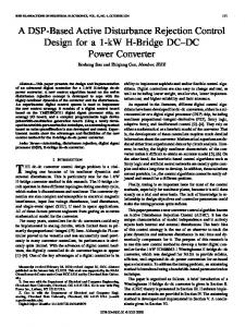
Fig. Source and
To avoid the problems of analog circuit such as ageing, variation of component values with variation of temperature, digital controller is used for shunt active power. In this paper, ICOSφ algorithm was implemented in a micro controller dsPIC 30 F 4011. The main operations to be carried out are explained as follows: Step1: Sensing source voltage, load currents and compensation currents injected by the active filter:
1(a): voltages
93
© 2009 ACADEMY PUBLISHER
SHORT PAPER International Journal of Recent Trends in Engineering, Vol 2, No. 7, November 2009 [3] Manjula G. Nair & G. Bhuvaneswari, “Design, Simulation and Analog circuit implementation of a three-phase shunt active filter using the I.Cosφ algorithm”, in Proc. 6th International Conf. On Power Electronics and Drive systems, PEDS05, Kuala Lumpur, Malaysia, Nov.2005, pp.553-556.
Two AD 7863 are used for sensing these quantities. AD 7863 is a bipolar ADC used for the conversion of analog quantities to corresponding digital values. Step 2: Extraction of fundamental component of load current: Biquad filter is implemented in terms of the transfer function K *ω 02
T lp ( s ) =
BIOGRAPHY:
⎛ ω0 ⎞ s2 + s ⎜ ⎟ + ω 02 ⎝Q ⎠
Ginnes K John did his B.Tech in Electrical and Electronics Engineering from Mar Athanasius College of Engineering, Kothamangalam, Mahatma Gandhi University, Kottayam, Kerala, India and M.Tech in Power Electronics from Amrita School of Engineering ,Amrita Vishwa Vidyapeetham University, Ettimadai, Tamil Nadu, India. He is presently working as lecturer at Adi Shankara Institute of Engineering and Technology, Kochi, Kerala. His areas of interest are Power Quality, Power Electronics, Electrical Drives and Control.
By considering gain K and quality factor Q is equal to 1,
ω 02 transfer function will be TFlp ( s ) = 2 s + sω 0 + ω 0 2
----
(1) Considering fundamental frequency, ω 0 = 2 ∗ π ∗ 50 , equation (1) becomes
T F lp ( s ) =
98696.04 s 2 + 314.159 s + 98696.04
Bilinear transfer function is done for converting S domain equation into Z domain by considering 3 kHz sampling frequency. Then transfer function become
Y(z) 0.0026 + 0.0052Z −1 + 0.0026Z −2 = X(z) 1 − 1.8904Z − 1 + 0.9008Z − 2 The output of low pass filter Y(z) can be written as Y(z) = 0.0026 X(z) + 0.0052 X(z − 1) + 0.0026 X(z − 2) TF =
+ 1.8904 Y(z − 1) − 0.9008 Y(z − 2) Step 3: Determining real component of load current: It is the instantaneous value of fundamental component of load current at negative zero crossing of source voltage. In AD 7863, 14th bit represents sign bit. If 14th bit is 1, it represents negative value and 0 represents positive value. Step4: Obtaining the desired source current waveforms: Unit amplitude sine wave generation is done using look up table. The real component of load current is multiplied with unit sinusoidal waves in phase with source voltage to obtain desired source current. The reference compensation current is obtained by subtracting desired source current from load current. The program for step 2 to step 4 was written in embedded C language and compiled with the help of MPLABC30 compiler.
Dr. Manjula G.Nair obtained her Masters degree in Power systems from University of Calicut, Kerala and Ph.D. degree from IITDelhi. Since 1995, she has been with the Department of Electrical Engineering, Amrita School of Engineering, Amrita Vishwa Vidyapeetham (University), India. Her areas of interest are FACTS controllers, Fuzzy and ANN based control of Power Systems, Power Quality, Hybrid and Active Filters.
V. CONCLUSION This paper presents analog circuit implementation of controller, based on ICOSφ algorithm, for shunt active power filters. The set up was tested with three phase diode bridge rectifier and results show that controller is able to provide effective current harmonics. Digital set up using micro controller dsPIC 30F 4011 were also done. VI. REFERENCES [1] Jos Arrillaga and Neville R. Watson, “power system harmonics”, John Wiley & Sons Ltd, 2nd edition, 2003. [2] Kim. S & Enjeti. P.N, "A New hybrid active power filter (APF) topology", IEEE Trans. Power Electronics, vol. 17(1), pp. 48-54, 2002.
94
© 2009 ACADEMY PUBLISHER
M.R.Sindhu was born in Thrissur in Kerala state, India on May 6, 1975. She did B.Tech (Electrical and Electronics Engineering) and M.Tech. (Power Systems) from University of Calicut, Kerala and currently doing Ph.D. in Amrita Vishwa Vidyapeetham. .She is teaching for ten years and presently, is Assistant Professor, Amrita School of Engineering, Ettimadai, Amrita Vishwa Vidyapeetham University. Her areas of interest are Power quality, Genetic Algorithm Application in Power systems.