2009 IEEE International Conference on Control and Automation Christchurch, New Zealand, December 9-11, 2009
FrPT4.5
Fuzzy Logic Controller on Automated Car Braking System M. Mamat, N. M. Ghani
Ordinary cruise control systems for passenger cars are becoming less and less meaningful because of the increasing traffic density rarely make it possible to drive at a preselected speed. However, in order to achieve high customer acceptance an intelligent cruise control system has to perform similarly to an experienced human driver. Therefore, it is necessary to adjust the following distance and the control dynamics according to the individual driver s needs. Applying fuzzy logic to intelligent cruise control seems to be an appropriate way to achieve this human behavior, because driver s experience can be transformed easily into rules. [4]
Abstract This paper deals with a Fuzzy Logic Controller (FLC) for an automated car braking system. The response of the system will be simulated by using Fuzzy Logic Toolbox in MATLAB. The purpose of this controller is to brake a car when the car approaches an obstacle at a specific range. In this paper, Fuzzy Logic Controller is designed using the Fuzzy Logic Toolbox in MATLAB and then compared with PI and PD type Fuzzy Logic Controller. The FLC system designed uses four rules and three membership function. Braking performance will be observed for each controller type in term of distance and velocity to prevent collision or accident. Index terms ± Car Braking System, Fuzzy Logic Controller
I. INTRODUCTION
II. CAR BRAKE SYSTEM MODELING
Traffic congestion is a worldwide problem. This problem is mainly due to human driving which involves reaction times, delays, and judgment errors that may affect traffic flow and cause accidents. [1] In many such cases, the cause of the accident is driver distraction and failure to react in time. Advanced system of auxiliary functions has been develop to help avoid such accident and minimize the effects of collision should one occur. This is done by reducing the total stopping distance. [2] By that means, the car brake itself should have a good software system to assist a driver along the road. Electronic brake control system has been making the car safer for the past 25 years. In recent years, braking developments have led to significantly greater driving safety. [3] For the past few years, there are many car brake development that uses the involvement of the electronic roles such as the Intelligent Cruise Control (ICC), Antilock Braking Systems (ABS), Traction Control System (TCS) and the Sensotronic Brake Control (SBC). Many studies in this field depend upon a precise mathematical model of the vehicle. In fact, behaviors of the drivers are mostly based on the experience, not the exact mathematic computation. The model of vehicle is highly nonlinear function; it is difficult to find the precise model. Therefore, fuzzy logic systems have been designed by many researchers for automated driving controller since fuzzy system emulates the performance of a skilled human operator in the linguistic tulles that do not need use a mathematic model. [1] _______________________________________________
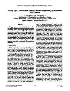
In this paper, the engine dynamic, skidding, slip and friction of the car is disregard. Therefore, using Newton s second law of motion, the force F causes acceleration: F = ma obstacle
v=y
25m
Fig. 1:
0
Model of a Car
Acceleration is the derivative of velocity y . y is the derivative of the position, y. Thus, a equals to y .Therefore, the differential equation models the motion of the car as F = my´ Assuming the mass of the car is 1500kg, the initial position which the car will be controlled to brake is 25m and the initial velocity is 10ms-1. We have thus identified the following constants: m = 1500kg y(0) = í25m y¶0) = 10ms-1
M. Mamat is with the Faculty of Electrical and Electronic Engineering, University Malaysia Pahang, 26300 Kuantan, Pahang, Malaysia (email:
[email protected]) N. M. Ghani is with the Faculty of Electrical and Electronic Engineering, University Malaysia Pahang, 26300 Kuantan, Pahang, Malaysia (e-mail:
[email protected])
978-1-4244-4707-7/09/$25.00 ©2009 IEEE
y
Considering that once the speed is zero, the car will not move anymore. The variable force, F is thus negative or zero, since the brake is the only means of control. 2371
2 According to specification, when a brake is applied to a car of a speed of 80 km/h which in turn is 22.22ms-1 will bring the speed to zero at a distance of 27.3 m. v = 80km/h = 22.22ms-1 y = 27.3m Knowing that kinetic energy is converted to work: Ke = ½ mv2 W = Fs
Fig. 3:
Close Loop Diagram for Car Braking System.
A. Fuzzy
Logic Controller Design In this study, for the car brake controller design, there are two inputs and one output that are design through for the fuzzy logic controller. The inputs are position and velocity. The output is the brake. The position represents the distance of the car from the obstacle detected. Velocity is measured from the velocity of the car towards the obstacle and brake represents the force of the car brake needed to stop the car. Rules are develop according to the input and output sets. It consists of four different rules which are:
Therefore; ½ mv2 = Fy ½ (1500kg)(22.22ms-1)2 = F(27.3m) F = my¶2 2y = (1500kg)( 22.22ms-1)2 2(27.3m) = 13600 N
I. Rule 1: If position is long and the velocity is fast, then brake is no. II. Rule 2: If position is long and the velocity is slow, then brake is no. III. Rule 3: If position is short and the velocity is fast, then brake is yes. IV. Rule 4: If position is short and the velocity is slow, then brake is no.
Therefore, it was assume that the automatic brake system limits the magnitude of the brake force to 13600N. The control signal is thus subject to the constraints í13 600N F 0N TABLE 1 PARAMETER VALUE FOR THE CAR BRAKING SYSTEM [7]
Mass of the car, m Initial Velocity of the car, v Position to Start the Car Brake, y Car Braking Force, F
: : : :
Correspond with the rules that are available, for braking equals to no means 0N of brake force is applied to the system. For yes brake output, 13600N of braking force is given to the system. Hence, from the system, it is clear that for rule 1, 2 and 4 will results in 0N of braking force. As for rule 3, the brake output is 13600N.
1500 kg 10 m/s -25 m 13600 N
III. CONTROLLER DESIGN In this section, a car brake is designed and simulated by Fuzzy Logic Controller. Initially, a basic Fuzzy Logic Controller is designed and simulated to observe the system. Then, the PD type Fuzzy Logic and PI type Fuzzy Logic will be investigated to compare the output different.
Fig. 4: Surface Viewer for Fuzzy Logic Controller Output.
Fig. 2:
To see clearly the response of Fuzzy Logic Controller built, it is then simulated using MATLAB simulink.
Simplified Block Diagram for P,I & D Controller.
2372
3 B. PD-Fuzzy Logic Controller Design PD-Fuzzy Logic Controller is the enhance design from the original Fuzzy Logic Controller develop previously. The purpose is to see the response when a Proportional Derivative Gain, Kp and Kd is applied to the original system. C. PI-Fuzzy Logic Controller Design PD-Fuzzy Logic Controller is investigated to see the response when a Proportional Integral Gain, Kp and Ki is applied to the original system. IV. SIMULATION RESULT AND DISCUSSION The subjects that are to be measured are braking force, car velocity, and position of the car ahead of the obstacle. Hence, by the simulation done, these three elements will be observed to determine the ability and the performance for all Fuzzy Logic Controller types.
Fig. 7: Position versus Time Graph for FLC.
From the graph in figure 6, initial velocity of the car is 10m/s. The velocity is then reduce to 0m/s due to the braking force applied to the car during 1.9s until 3s. From the graph shown in figure 7, it shows that the car started to sense the obstacle at 25m distance. As the car approaching to the obstacle, it brakes slowly and stops at approximately less than 1m from the obstacle.
A. Fuzzy Logic Controller
B. PD-Fuzzy Logic Controller
Fig. 5: Braking Force versus Time Graph for FLC.
By looking at the resultant graph in figure 5, it shows that the system started to brake the car at approximately 1.9s with 13600N braking force until 3s and the car stopped after 3s. Fig. 8: Braking Force versus Time Graph for PD-FLC.
From the graph in figure 8, it is clearly shown that the brake is applied at 1.1s until 2.1s, which is faster in action. The same force 13600N is applied as on Fuzzy Logic controller before. Whereas the graph in figure 9 shows that same velocity, 10m/s is reduced once the brake is applied due to braking force at 1.1s. While in Figure 10, the car stops at 8m from the obstacle, which is better and safer compared to FLC controller.
Fig. 6: Velocity versus Time Graph for FLC.
2373
4
Fig. 9: Velocity versus Time Graph for PD-FLC.
Fig. 12: Velocity versus Time Graph for PI-FLC.
For PI-FLC, by referring to Figure 11, the brake is applied approximately at 1.6s but not smooth braking. As in figure 12, the car velocity is reduced from 10m/s and fully stops at 6.6s which is longer than other Fuzzy Controller. For figure 13, it shows that the car stops at 2.5m ahead from the obstacle due to braking action.
Fig. 10: Position versus Time Graph for PD-FLC.
C. PI-Fuzzy Logic Controller
Fig. 13: Position versus Time Graph for PI-FLC.
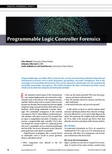
C. Discussion The results are then transferred into 1 graph for each subjects to be measured, position, velocity and braking force. By combining all three results together in 1 graph, we can compare the performance of each system. Based on Figure 14, the braking time for all types of controller is different. But it is clearly seen that the fastest braking system to response is the PD-FLC, then PI-FLC followed by FLC respectively. Due to braking force, the velocity of the car will varies too. From the figure 15, the velocity drop for PD-FLC is the best because it able to brake faster than other system. But PI-FLC takes the longest time to brake as it only stops the car at 6.6s due to not smoothly braking.
Fig. 11: Braking Force versus Time Graph for PI-FLC.
2374
5 V. CONCLUSION By comparing all of the controllers that have been simulated, it can be concluded that PD-Fuzzy Logic Controller give best performance in braking system compared to the other type of Fuzzy Controller. PD-FLC is able to brake the car faster than PI-FLC and FLC. In addition, safety is guaranteed and able to avoid collision due to faster braking action. However, the conventional Fuzzy Logic Controller constitutes a reference for the assessment of the performance of the system controller. For a future development of this project, the Fuzzy Logic Controller designed can be enhanced by applying more rules. By then, it can produce better response. By applying more rules, it means that more parameters and measurement should be considered. The response should be better when combining all PID-FLC controller and can be applied to a real hardware model to observe the real response and yet can improve the system.
Fig. 14: Braking Force versus Time Graph.
VII. REFERENCES [1] Cai, L., Rad, A,. B., Chan, W., L., Ho, M., L., A Neural-Fuzzy Controller for Intelligent Cruise Control of Vehicle in Highways Available at: http://www.ieee.org [2] 23th March 2007, Citing Internet Sources URL http://www.auto-innovation.com/actu-news/ [3] Jost, K. (2003). Bosch Expands Brake Offering with Electronics. Automotive Engineering Online Article Available at: http://www.sae.org/automag/electronics/09-2003/ [4] Muller, R., Nocker, G., Intelligent Cruise Control with Fuzzy Logic. Available at: http://www.ieee.org [5] Simon, D., (2003). Embedded System Programming: Introduction to Fuzzy Control. Available at: http://www.academic.csuohio.edu/simond/fuzzyintro [6] Altrock, V., C., Fuzzy Logic in Automative Engineering: Fuzzy Application Library. Available at: http://www.fuzzytech.com/e/e_a_esw.html [7] Ahmad, M., I., (2004). Fuzzy Logic for Embedded System Application : Elsevier Science (USA). [8] Naranjo, J., E., Reviejo, J., Gonzalez, C., Garcia, R., Pedro, T., D., (2003). A Throttle and Brake Fuzzy Controller: Towards the Automatic Car: Springer Berlin/ Heidelberg. [9] Siler, W., Buckley, J., J., (2005). Fuzzy Expert System and Fuzzy Reasoning: John Wiley and Sons Inc. [10] (2006), Fuzzy Logic Toolbox for Use with MATLAB: The Math Work Inc
Fig. 15: Velocity versus Time Graph.
Fig. 16: Position versus Time Graph.
Referring to the figure 16 , the car stop at 8m for PDFLC, continued with PI-FLC with 2.5m and lastly FLC with 1m respectively.
2375