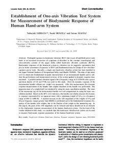
[30] Rajani, K., Mudi, K., and Nikhil, R. Pal., 1999: âA. Robust Self-Tuning Scheme for PI- and PD-Type Fuzzy. Controllersâ. IEEE Transactions on fuzzy systems, ...
International Journal of Computer Applications (0975 – 8887) Volume 77– No.3, September 2013
Fuzzy Stabilization Loop of One Axis Gimbal System Maher Abdo
Ahmad Reza Vali
Ali Reza Toloei
Department of Electrical Engineering MUT, Tehran
Department of Electrical Engineering MUT, Tehran
Department of Aerospace science SBU, tehran
ABSTRACT The application of inertial stabilization system is to stabilize the sensor’s line of sight toward a target by isolating the sensor from the disturbances induced by the operating environment. The purpose of this paper is to present a model of control servo system for one axis gimbal mechanism using fuzzy PID type controller. The gimbals torque relationships are derived using Newton’s law considering the base angular motion and dynamic unbalance. Then, the stabilization loop is constructed and the proposed fuzzy controller is designed. The overall control system is simulated using MATLAB/Simulink, then the system performance is investigated in different cases for both conventional PI and fuzzy PID controller. A comparison study is made based on some performance criteria. The results obtained in different conditions confirms that a further improved system performance can be achieved using the proposed fuzzy controller as compared to the conventional PI controller. The simulation results proves the efficiency of the proposed fuzzy controller which offers a better response than PI one, and improves further the transient and the steady-state performance.
General Terms Inertial stabilization systems, fuzzy control, servo systems
Keywords Gimbal System, Rate Gyro, Line of Sight, Stabilization Loop
1. INTRODUCTION The optical equipments (such as IR, radar, laser, and television) have found a wide use in many important applications, for example image processing, guided missiles, tracking systems, and navigation systems. In such systems, the optical sensor axis must be accurately pointed from a movable base to a fixed or moving target. Therefore, the sensor’s line of sight (LOS) must be strictly controlled. In such an environment where the equipment is typically mounted on a movable platform, maintaining sensor orientation toward a target is a serious challenge. An Inertial Stabilization Platform (ISP) is an appropriate way that can solve this challenge [1]. These systems can provide stabilization to the sensor while different disturbances affect it. The most important disturbance sources are the base angular motion, the dynamics of gimbaled system, and the gimbal mass unbalance. (ISPs) are usually constructed as an assembly of structure, bearings, and motors called a gimbal to which a gyroscope is placed [2]. It has been shown earlier that the jitter on the LOS can be reduced by mounting the electro optical EO payload on a set of gimbals. Gimbals are precision electro-mechanical combinations which are mainly used to isolate the optical equipment from the disturbance caused by
the operating environment, such as various disturbance torques and body motion [3]. Such systems are usually required to maintain stable operation and guarantee accurate pointing and tracking for the target even when there are changes in the system dynamics and operational conditions. The mathematical model and the control system of gimbal systems have been studied in many researches. Concerning the mathematical model, several derivations have been proposed using different assumptions. In [4], the kinematics and geometrical coupling relationships for two degree of freedom gimbal assembly have been obtained for a simplified case when each gimbal is balanced and the gimbaled elements bodies are suspended about principal axes. The equations of motion for the two axes gimbal configuration have been presented in [5] based on the assumption that the gimbals are rigid bodies and have no mass unbalance. Both researches [4, 5] mentioned above have not been simulated. A single degree of freedom (SDOF) gimbal operating in a complex vibration environment has been presented by Daniel in [6]. It has been illustrated how the vibrations excite both static and dynamic unbalance disturbance torques, which can be eliminated by statically and dynamically balancing the gimbal, which is regarded costly and time consuming [6]. In [7], the motion equations have been derived on the assumption that gimbals have no dynamic mass unbalance, and the mass distribution of gimbals is symmetrical with respect to the frame axes considered. In addition, the effects of base angular velocities were not highlighted. In [8], a two axes gimbal mechanism was introduced and just the modeling of azimuth axis was focused, and the elevation angle was kept fixed and cross moments of inertia were taken to be zero. In both [5] and [9], the dynamical model of elevation and azimuth gimbals have been derived on the assumption that gimbals mass distribution is symmetrical with respect to the gimbals frame axes. Therefore, the products of inertia were neglected, and the model was simplified. On the other hand, the control system of gimbal configurations has been constructed using different control approaches. In [7], a proxy-based sliding mode has been applied on two axes gimbal system. Also, [10] proposed the sliding mode control under the assumption of uncoupled identical elevation and azimuth channels. In [11], modern synthesis tools such as linear quadratic regulator (LQR) or linear quadratic Gaussian with loop transfer recovery (LQG/LTR) control for a wideband controller have also been used in the line of sight stabilization for mobile land vehicle. Also, [12] presented a linear quadratic Gaussian (LQG) algorithm for estimating and compensating in real time a particular class of disturbances. Besides conventional control methods mentioned above, some advance control techniques, such as fuzzy logical control (FLC) [13], robust control [14], variable structure control (VSC) [15], were also applied in LOS inertia stabilization systems during recent years. In [15],
6
International Journal of Computer Applications (0975 – 8887) Volume 77– No.3, September 2013 a variable structure-augmented adaptive controller for a gyromirror line of sight stabilization platform has been developed. The H∞ control methodology was used in [16] to design a high performance controller so as to control the rate of the line of sight. [17] Introduced an efficient full-matrix fuzzy logic controller for a gyro mirror line-of-sight stabilization platform. However, a majority of these algorithms were complex and difficult to be realized. In recent years, the fuzzy control technology has been developed successfully. It improves the system control performance, and has the good adaptability for the system with nonlinear mathematical model and uncertain factors [18]. It can be realized that the importance of gimbal systems gave rise to be investigated in a lot of papers as mentioned above. Without doubt, these researches have contributed in studying and explaining gimbal systems, but the model of such systems is still difficult and complicated to be understood by engineers because the vast majority of these researches have interested in the two or multi axes gimbal systems as well as these systems have been investigated considering the inertia cross coupling between axes. Therefore, this paper is devoted for twofold purpose. First, to present the model of one axis gimbal system in order to simplify the picture of the gimbal systems and to further investigate the properties of this configuration. In another words, this paper forms a primary theoretical base for designing a multi axes gimbal systems. Second aim is to introduce a self-tuning PID-type fuzzy technique for one axis gimbal system. The paper is organized in the following manner. The problem is formulated and the equation of gimbal motion is derived in section 2 and 3 respectively. Afterwards, the stabilization loop is investigated and constructed in section 4. Then, in section 5 the proposed fuzzy controller is designed. The simulation results are introduced in section 6. Finally, the conclusion remarks are highlighted in section 7.
2. PROBLEM FORMULATION
( platform ) A
r
Ae
j
i
e
k d
Fig 1: A single-axis gimbal mechanism. When the rate command input is zero or absent, the system attempts to null the total torque applied to the gimbal, which requires that the stabilization closed-loop generates a control torque at the motor that is equal and opposite to the net disturbance torque. TD
c
Rate command
E
Controller
DC motor
Tm Motor torque
Rate error
Gyro rate feedback
Torque disturbance
Inertia
T Total torque
Rate gyro
1 Js
Ae
LOS rate
Fig 2: LOS stabilized servo control loop. From Figure 2, it can be seen that
Ae 1 T J Ae s J Ae J T Js
Regarding the rotational motion, Newton’s first law states that a torque must be applied on the body to make it accelerating with respect to an inertial frame. Moreover, utilizing Newton’s second law, it can be established that if a net torque T is applied to a homogenous rigid mass having a moment of inertia J, then the body develops an angular acceleration α [2] according to
The control loop introduced works as stabilization system when the rate command input c is zero, which means that
T J . (1) Therefore, it can be concluded that to prevent an object from rotating with respect to inertial space, the applied torque must be zero. However, even in a carful electromechanical design, multiple torque disturbances sources can affect on a real mechanism causing excessive motion or jitter of (LOS). Also, a means is required to control the object so that it can accurately respond to command inputs. Therefore, rate or displacement gyros are typically attached to the object to measure the inertial rotation about the axes that require stabilization and control. The gyro is used in a closed-loop servo system to counteract the disturbances and at the same time, allow the object to be controlled from external command inputs [2]. The single-axis stabilized gimbal is shown in Figure 1. It is clear that the purpose of the gimbal is to isolate the stabilized object from base rotation, and allow (LOS) to be pointed. The block diagram in Figure 2 shows the gimbal stabilization system. It is typically configured as a rate servo. That is, the system attempts to null the difference between the rate command input c and the angular rate of the gimbal
3. MATHEMATICAL MODEL OF GIMBAL MOTION
(2)
the control system output Ae must be zero. While this system tries to track the nonzero rate command input. As a result, the problem can be formulated as follows. The servo control in general can be broken into two fundamental classes. The first class deals with command tracking. It addresses the question of how well does the actual motion follow what is being commanded. The second general class of servo control addresses the disturbance rejection characteristics of the system. Disturbances can be anything from torque disturbances on the motor shaft to incorrect motor parameter estimations used in the feed forward control.
In this research, two reference frames are interested as shown in Figure 1. Frame P fixed to the fuselage body (base) with axes i , j , k , and frame A fixed to the gimbal (stabilized object) with axes r , e , d where r-axis coincides with the sensor optical axis. The center of rotation is at the origin of the two frames. A transformation between frame P and A is made in terms of positive angle ε (gimbal angle) about the eaxis.
Ae .
7
International Journal of Computer Applications (0975 – 8887) Volume 77– No.3, September 2013
cos C 0 sin
A P
0 sin 1 0 0 cos
(3)
The inertial angular velocity vectors of frames P and A, respectively are
P I
p
pi pj , A pk
Ar AI Ae Ad
(4)
Where pi , p j , pk are the base angular velocities of frame P in relation to inertial space about i, j, and k axes respectively, and Ar , Ae , Ad are the gimbal angular
view, the "inertia terms" on the right represent unwanted disturbances. They will enter the control system in the same point as an external torque; consequently, they can be regarded as torque disturbance TD (Figure 2). 2 2 TD ( Ad Ar ) Ar Ad Ard ( Ar Ad )
Ade ( Ad Ae Ar ) Are ( Ar Ae Ad )
From the control point of view, it is suitable to let Tm represent only the motor torque. Therefore, the equation (12) can be represented by the block diagram in Figure 3. It is clear that the motor torque and the disturbance torques are inputs to an integrator which includes the moment of inertia Ae , and the output is the angular velocity Ae .
TD
velocities in relation to inertial space about the r, e, and d axes respectively. The inertia matrix of the gimbal is
Ar A J A re A rd
A re Ae A de
Tm
A rd A de A d
(5)
Ar , Ae , Ad are gimbal moments of inertia about r, e, and d axes, Are , Ard , Ade are gimbal moments products of inertia. The angular velocities A is the output of the Where
e
stabilization loop (servo control system), the purpose of which is to make it possible to keep Ae 0 despite disturbances, and by that keep the sensor nonrotating in inertial space [5]. Ae can be measured by a rate gyro placed on the gimbal. Utilizing (3), the angular velocities of the stabilized object are
Ar Pi cos Pk sin Ae Pj
(b)
Ad Pi sin Pk cos
(c)
( a) (6)
In [5], by Newton’s second law, the external kinematic torques applied to the body A can be written as follows
T Where
A
d A H AA I AH dt
H is the angular momentum given by A H A J . AA I
Ar Ar Are Ae Ard Ad H r H Are Ar Ae Ae Ade Ad H e Ard Ar Ade Ae Ad Ad H d The moment equation for a rotating frame is H r Ae H d Ad H e T H e Ad H r Ar H d H d Ar H e Ae H r A
(7)
(8)
(9)
(10)
The torque provided by the DC motor and applied about the gimbal e-axis is the e-component of matrix (10).
Tm He Ad H r Ar H d
(11)
This equation can be obtained as a differential equation for the base angular velocity in the following form 2 2 Ae Ae Tm ( Ad Ar ) Ar Ad Ard ( Ar Ad ) (12) Ade ( Ad Ae Ar ) Are ( Ar Ae Ad )
Tm represents the sum of the motor torque and external imperfection disturbance torques. From stabilization point of
(13)
1 Ae s
Ae
Fig 3: Gimbal motion equation. Equation 13 shows that the torque disturbance is caused by the base angular motion and the gimbal inertia parameters. Therefore, when the base is nonrotating
Pi
Pj Pk 0 the disturbance term is zero and just
the motor torque Tm affects on the platform (stabilized object A). With regard to inertia parameters, it must be mentioned that the dynamic mass unbalance is the result of a nonsymmetrical mass distribution called Product of Inertia (POI) [6]. The dynamic unbalance concept can be indicated by the inertia matrix. Therefore, if the considered gimbal has a symmetrical mass distribution with respect to its frame axes, then the gimbal has no dynamic unbalance and its inertia matrix is diagonal. Also, if the gimbal has a non-symmetrical mass distribution with respect to its frame axes, then the gimbal has dynamic unbalance and its inertia matrix is not diagonal. Actually, in most papers, the model of gimbal system has been simplified using certain choices of inertia parameters to reduce the effects of dynamic mass unbalance which is considered an inevitable imperfection that can be encountered even in a well designed system. For example, in [4, 5], it has been assumed that the gimbal has no dynamic unbalance i.e., Are Ard Ade 0 . When this assumption is applied on the gimbal model indicated in (12), the equation of gimbal motion will be simplified to AeAe Tm ( Ad Ar )ArAd . In this paper, it is assumed that the gimbal has dynamic mass unbalance, so the model indicated in equation (12) will be interested.
4. STABILIZATION LOOP CONSTRUCTION It can be seen from Figure 2 that the stabilization loop is constituted of controller, DC motor, platform, and rate gyro. These components are identified as follows. Although, the researchers tried to utilize and apply many different modern techniques to control inertia stabilization systems, the conventional PID and its constructors are still the most used approach due to their simple structure, cheap costs, simple design and high performance [19]. Therefore, In order to evaluate the efficiency of proposed fuzzy controller, PI controller (equation 14) has been utilized to be compared later with the performance of the proposed fuzzy controller.
8
International Journal of Computer Applications (0975 – 8887) Volume 77– No.3, September 2013
K ( s) 0.09
12.5 s
M 1kg and radius r 14 cm , so J L 9.8 103 Kg.m2 .
(14)
Any servo motion control system should have an actuator module that makes the system to actually perform its function. The most common actuator used to perform this task is the DC servomotor. DC motor is one of the simplest motor types. It is widely preferred for high performance systems requiring minimum torque ripple, rapid dynamic torque, speed responses, high efficiency and good inertia [20]. These motors speedily respond to a command signal by means of a suitable controller. In this kind of motors, the speed control is carried out by changing the supply voltage of the motor [21]. DC motor from NORTHROP GRUMMAN Company (Table 1) is utilized.
In this paper, the 475T rate gyroscope from the US Dynamics company is considered. Table 2 indicates this gyro specification. Table 2: Gyroscope specifications. Characteristic
Value
Input Rate
± 40 to ±1000 o/sec
output
AC or DC
Scale Factor
Customer Specification
Natural Frequency
20 to 140 Hz
Damping Ratio
0.4 to 1.0
Table 1: DC motor specifications. Parameter
The rate gyro can be modeled in the second order system typically [22]. For the gyro of natural frequency n 50 Hz , and the damping ratio 0.7 the gyro transfer function is
Value
Nominal voltage No load speed
ua
27 V
nL
Terminal resistance
303 rpm
GGyro ( s)
4.5 Ω
Ra
Terminal inductance La
0.003 H
Torque constant KTM
0.85 Nm/A
Back EMF K e
0.85 V/rad/sec
Rotor inertia
Damping ratio
am
0
The transfer function of DC motor shown in Figure 4 can be obtained as follows TD
ua
1 La S Ra
KTM
Tm
1 J m S am
m
Ke
Fig 4: The block diagram of DC motor.
Gm ( s )
m ( s ) ua ( s )
KTM
La s Ra J m* s am* K e KTM
(15) 24637.68 ; a 0 m s 2 1500s 20942 Where m is the motor’s angular velocity, ua the motor’s
If gimbal design is not proper, the control algorithms may become complex and it may not be possible to meet the performance criteria [23]. While the well-designed gimbal assembly reduces the jitter of sensor’s line of sight and hence needs a simpler control system [23, 24] which simplifies the implementation of control laws in real time. The drawback of the conventional PID appears when the control system work under variable conditions. Therefore, in systems such as gimbal system proposed, PID controller can not maintain the good performance unless the controller parameters are retuned. The progress report [25] pointed out that the adaptive control technique is the future development direction of LOS inertia stabilization systems. Recent years, fuzzy logic control has been increasingly developed. Fuzzy logic controllers fall into the class of intelligent control system. An intelligent control system combines the technique from the field of artificial intelligent with those of control engineering to design autonomous system that can sense, reason and plan, learn and act in intelligent manner [26]. Basically, fuzzy controller comprises of four main components, fuzzification interface, knowledge base, inference mechanism and defuzzification interface [26]. Figure 5 shows components of fuzzy logic controller. Fuzzy logic controller
armature voltage, Tm the torque generated by the motor, TD the
torque
disturbance.
Also,
J m J m J L
(16)
5. PROPOSED CONTROLLER DESIGN
0.0017 Kgm2
Jm
n2 2500 ( s 2 2n s n2 ) ( s 2 70s 2500)
e
and
am am aL where J L is the platform’s moment of inertia, aL is the load’s damping ratio. The platform represents the motor load, which is attached to the output of the gears or directly to the shaft motor. The platform is modeled based on its moment of inertia J L that depends on its dimensions and its position respect to the axis of rotation. In this paper, a discus is proposed to represent the platform where its mass
Rule base
e
Fuzzification
Error computing Reference input
Inference Michanism
Defuzification
Process Actual output
Fig 5: Components of fuzzy logic controller. Fuzzification converts input data into suitable linguistic values, while defuzzification yields a non fuzzy control action from inferred fuzzy control action. The rule base is a decision making logic which is, simulating a human decision process,
9
International Journal of Computer Applications (0975 – 8887) Volume 77– No.3, September 2013 inters fuzzy control action from the knowledge of the control rules and linguistic variable definitions. The fuzzified input variables are used by the inference mechanism to evaluate control rules stored in the fuzzy rule-base. The result of this evaluation is a single fuzzy set or several fuzzy sets. In literature, various structures for fuzzy PID (including PI and PD) controllers and fuzzy non-PID controllers have been proposed. The conventional fuzzy PID controller needs three inputs and the rule base has three dimensions, it is more difficult to design the rule-base. On the other hand, the fuzzy PD type controller difficultly eliminates the steady state error which can be completely removed using fuzzy PI type controller. The fuzzy PI type controller, however, achieves poor performance in transient response especially when it is used for higher order process [27]. In order to obtain the advantages of these two controllers, it is useful to combine them in what can be named fuzzy PID type controller that has just two inputs and two dimensions rule base. Figure 6 shows the construction of the proposed fuzzy PID type controller which will be utilized in this paper instead of the conventional PID.
e e
Ke
E
Kd
E
Fuzzy logic controller
U
uc
u2
Ke , K d are the input scaling factors of error and
change of error, and , are the output scaling factors. The output of PID-type fuzzy controller is given by
uc U Udt
(17)
Based on what has been made in [28], the relation between input and output variables of fuzzy parameters is
U A PE DE ; E Ke e , E Kd e
e , e and U.
For the membership functions used, NL, NM, NS, ZR, PS, PM, PL denotes negative large, negative medium, negative small, zero, positive small, positive medium, and positive large, respectively. All membership functions are defined on the [-1,1] closed interval. All the scaling factors Ke , Kd , , are used to map the related crisp values to their fuzzy universe of discourse. The control output U can be determined from the method of the center of the gravity. The rules of the proposed controller are expressed as follows: If { e is ZR and e is ZR}, then {U is ZR}. The rule base is constructed based on the following approach: when the system output is far from the desired output i.e. e is PL and
(18)
e is ZR then U is selected to be PL in order to decrease the error value and bring the system state to the desired value rapidly. If the error e is ZR and it tends to increase due to
(19)
the nonzero e thus, U should not be zero (for example, if e is ZR and e is NM then U is NM). When both e and e are zero which is the desired case and the system does not need any control input therefore, U is selected to be ZR. The fuzzy PID type control rules are indicated in Table 3.
The output of fuzzy PID type controller is
uc A At K e Pe K d De Ke P edt K d De
fuzzification of the inputs e , e and output U variables.
Fig 7: Membership functions of
u1
Fig 6: Fuzzy PID type controller. Where
by modifying either its scaling factors or membership functions or, both of them is called a self-tuning fuzzy controller. On the other hand, when a fuzzy controller is tuned by automatically changing its rules then it is called a selforganizing fuzzy controller [30]. Of the various tuning parameters, scaling factors have the highest priority due to their global effect on the control performance [30]. Therefore, the proposed controller is self-tuning fuzzy controller which is tuned by modifying its input scaling factors. Seven triangular membership functions indicated in Figure 7 are used for the
These control components can be divided into proportional Ke P Kd D , integral Ke P , and derivative Kd D . The design parameters of the fuzzy PID controllers can be summarized within two groups [29]: Structural parameters, and tuning parameters. Structural parameters, which are usually determined during off-line design, include input/output variables to fuzzy inference, fuzzy linguistic sets, membership functions, fuzzy rules, inference mechanism and defuzzification mechanism. Tuning parameters include scaling factors and parameters of membership functions. The selection of tuning parameters is a critical task, which is usually carried out through trail and error or using some training data. Also, these parameters can be calculated during on-line adjustments of the controller to enhance the process performance, as well as to accommodate the adaptive capability to system uncertainty and process disturbance [27]. The fuzzy controller is regarded adaptive if any one of its tunable parameters (scaling factors, membership functions, and rules) changes when the controller is being used; otherwise it is conventional fuzzy controller. An adaptive fuzzy controller that fine tunes an already working controller
Table 3. Fuzzy PID type rule base.
e/e
NL
NM
NS
ZR
PS
PM
PL
NL
LN
LN
LN
LN
MN
SN
ZE
NM
LN
LN
LN
MN
SN
ZE
SP
NS
LN
LN
MN
SN
ZE
SP
MP
ZR
LN
MN
SN
ZE
SP
MP
LP
PS
MN
SN
ZE
SP
MP
LP
LP
PM
SN
ZE
SP
MP
LP
LP
LP
PL
ZE
SP
MP
LP
LP
LP
LP
In general, the inertial stabilization systems work under variable conditions especially the base angular velocities. The most dominant parameters in one axis gimbal system is pj .
10
International Journal of Computer Applications (0975 – 8887) Volume 77– No.3, September 2013 It is realized that whenever
pj
increase, the system response
overshoot unacceptably increases. It is known that the integral and proportional parameters have a great influence on the stable and dynamic performance of control system which is usually evaluated using the concepts of maximum overshoot, rise time, settling time, and steady state error. It is noted that the input scaling factor K e exists in both integral and proportional terms therefore; it is selected to be tuned on-line based on the values of pj , while the other tuning parameters
, , Kd are adjusted off-line based on the knowledge about
In order to take into account the effect of base angular motion, the rate (equation 6-b) must be fed back to the DC motor through the motor electrical constant (back emf constant). In the simulation tests, the following values are considered; the input rate is c 10 deg sec while
Pj changes from zero to 14 deg/sec. Based on what has carried out above, the complete simulink model of servo control system introduced can be constructed using MATLAB as shown in Figure 9. Pk Pj Pi
the process to be controlled and sometimes through trial and error to achieve the best possible control performance. Table 4 indicates the values of these off-line adjusted parameters. c
Table 4. Off-line adjusted parameters. Parameter
Kd
Elevation
0.01
0.08
13
Azimuth
0.02
0.25
25
TD
E
Controller
DC motor
Rate error
Ke
1 S
FLC
U
d dt
Error
e K d
T Total torque
platform
Ae
Pj
LOS rate
Rate gyro
integrator
LOS angle
Fig 9: Simulink model of servo control system.
This on-line tuning operation improves further the performance of the transient state and steady state of one axis gimbal system using the proposed fuzzy PID type controller shown in Figure 8.
e
Motor torque
Gyro rate feedback
pj
Tm
Dynamic disturbance Disturbance torque torque
uc
At first, it is useful to graphically illustrate the principle of gimbal system work which depends on Newton’s second law (equation 1), then to ensure that the control system, which has been built utilizing the gimbal model obtained in (12), can accurately provide stability to the object A. The diagrams indicated in Figure 10 show how the closed-loop control system generates a control torque at the motor that is equal and opposite to the net disturbance torque. Therefore, the object is prevented from rotating with respect to the inertial space. the applied torque with simulink 0.08
Fig 8: Simulink model of fuzzy PID type controller. 0.06
In order to establish the on-line tuning of
Ke ,
a parametric
against every value of the angular velocities
pj
Ke
along the
the torque (Nm)
0.04
study is applied to obtain the most suitable value of
0.02
interval [0-14] deg/sec. As a result of this parametric study, the following relation can be obtained
Ke Pj 0.0093Pj2 0.0371Pj 0.7933
(20)
0
-0.02
-0.04
6. SIMULATION AND RESULTS Before the beginning of simulation, there are some ideas and concepts which must be confirmed, clarified and specified. It was mentioned in equation (13) that the torque disturbance is zero when the base is nonrotating Pi Pj Pk 0 .
The geometric properties of the gimbal mechanism (Figure 1) indicates that the rate
Pj
is the most
dominant parameter in the torque disturbance term
TD .
disturbance torque motor torque total torque
0
1
2
3
4
5 time(sec)
6
7
8
9
10
Fig 10: The total applied torque. Afterwards, the time step response of the servo control system for the conventional PI and fuzzy controllers, then a comparison study is carried out to investigate the performance of the proposed fuzzy controller in terms of the performance criteria. The desired performance requirements of the servo system proposed are Rise time tr 0.2 sec .
Therefore, this parameter was used in the
Settling time ts 0.35 sec .
tuning operation. The total moment of inertia seen from the motor side is J m J L 11.5 103 kg.m2 .
Maximum overshoot M p 20 % .
Steady state error ess 0 . Naturally, the required performance criteria are defined according to the application in which the gimbal system is
11
International Journal of Computer Applications (0975 – 8887) Volume 77– No.3, September 2013 used. The criteria mentioned above represent the requirements that must generally be satisfied in any control system. In order to evaluate the efficiency of the proposed fuzzy controller, the system responses are obtained for many different values of the base angular velocity pj . As examples, some system responses are displayed in Figures 11, 12, and 13 which reflect clearly the efficiency of the fuzzy PID type controller compared to the conventional PI.
are indicated in Table 5 utilizing the maximum percent overshoot (ov) and settling time t s criteria. The maximum percent overshot directly indicates the relative stability of the gimbal system. While the settling time is the time required for the response curve to reach and stay within a range about the final value of a size specified as an absolute percentage of the final value, usually 2 percent. The intended range is indicated by two red lines in Figures 11, 12, and 13. Table 5: Comparison results.
The step response of one axis stabilization loop
The base angular rate WAe (deg/sec)
12
Pj
10
8
6 Input Fuzzy PID PI
4
2
0
0
0.1
0.2
0.3
0.4
0.5 0.6 Time(sec)
0.7
0.8
0.9
The step response of one axis stabilization loop 14
(deg sec)
ov (%)
ts sec
ov (%)
ts sec
2 4 6 8 10 12 14
9.7 15.1 24.3 36.2 50 64.6 80
0.19 0.17 0.16 0.16 0.15 0.16 0.15
0 0 0 2 2.3 16 18.6
0.13 0.1 0.07 0.05 0.03 0.127 0.125
The results show how the angular rate increment affects badly in the gimbal system performance. This increment creates more overshoot and makes the response slow when conventional PI is used. While the fuzzy PID achieves fast response with lower overshoot.
7. CONCLUSION
12
The base angular rate WAe (deg/sec)
Fuzzy PID
1
Fig 11: Step response for Pj 3 deg sec .
10
8
6
4 Input Fuzzy PID PI
2
0 0
0.1
0.2
0.3
0.4
0.5 0.6 Time(sec)
0.7
0.8
0.9
1
Fig 12: Step response for Pj 7 deg sec .
In this paper a one axis gimbal system was introduced and its mathematical model derived utilizing Newton’s law by taking into account the base angular rates and the dynamic mass unbalance. Then, the stabilization loop was constructed and a self-tuning fuzzy PID type controller was designed. The proposed fuzzy controller can be simply tuned utilizing the base rate. The overall control system has been created and simulated using MATLAB/Simulink. A comparative study was carried out to test the performance of the proposed controller according to performance criteria. The results obtained have ensured the fuzzy controller efficiency. It has been shown that the proposed fuzzy controller can meet the variation of operation conditions and realize fast response with lower overshoot compared to conventional PI controller.
8. REFERENCES
The step response of one axis stabilization loop
[1] Masten, M.K., 2008: “Inertially Stabilized Platform for Optical Imaging Systems”. IEEE Control Systems Magazine, Vol. 28, pp. 47-64.
16 14
The base angular rate WAe (deg/sec)
PI
12
[2] Hilkert, J.M., 2008: “Inertially Stabilized Platforme Technology”. IEEE Control Systems Magazine, Vol. 28, pp. 26-46.
10 8 6 4 Input Fuzzy PID PI
2 0
0
0.1
0.2
0.3
0.4
0.5 0.6 Time(sec)
0.7
0.8
0.9
1
[3] Ravindra, S., 2008: “Modeling and Simulation of the Dynamics of a Large Size Stabilized Gimbal Platform Assembly”. Asian International Journal of Science and Technology in Production and Manufacturing, Vol. 1, pp. 111-119.
Fig 13: Step response for Pj 10 deg sec .
[4] Rue, A.K., 1974: “precision stabilization systems”. IEEE Trans. Aerospace and Electronic Systems. AES-10, pp. 34-42.
Both PI and fuzzy controllers achieve the response with out steady state error in the desired rise time. Therefore, to confirm the fuzzy controller efficiency, the comparison results
[5] Ekstrand, B., 2001: “Equation of Motion for a Two Axes Gimbal System”. IEEE Trans. On Aerospace and Electronic Systems, Vol. 37, pp. 1083-1091.
12
International Journal of Computer Applications (0975 – 8887) Volume 77– No.3, September 2013 [6] Daniel, R., 2008: “Mass properties factors in achieving stable imagery from a gimbal mounted camera”. Published in SPIE Airborne Intelligence, Surveillance, Reconnaissance (ISR) Systems and Applications V. 6946. [7] Özgür, H., Aydan, E., and İsmet E., 2011: “Proxy-Based Sliding Mode Stabilization of a Two-Axis Gimbaled Platform”. Proceedings of the World Congress on Engineering and Computer Science, San Francisco, USA (WCECS), I. [8] Ravindra, S., 2008: “Modeling and Simulation of the Dynamics of a Large Size Stabilized Gimbal Platform Assembly”. Asian International Journal of Science and Technology in Production and Manufacturing, Vol. 1, pp. 111-119. [9] Khodadadi, H., 2011: “Robust control and modeling a 2DOF Inertial Stabilized Platform”. International Conference on Electrical, Control and Computer Engineering, Pahang, Malaysia. [10] Smith, B.J., Schrenck, W.J., Gass, W.B, and Shtessel, Y.B., 1999: “Sliding mode control in a two axis gimbal system”. in Proc. IEEE Aerospace Applicat. Conf, Vol. 5, pp. 457–470. [11] Willian, B., and Steven, P.T., 1989: “Optimal motion stabilization control of an electrooptical sight system”. Proc. SPIE Conference, Vol. 1111, pp. 116–120. [12] Hullender, L. Bo, and DeRenzo, D., M., 1998: “Nonlinear induced disturbance rejection in inertial stabilization systems”. IEEE Trans, Vol. 6, pp. 421–427. [13] Krishna Moorty, J.A.R., Marathe, R., and Hari B., 2004: “Fuzzy controller for line of sight stabilization system”. Optical Engineering, Vol. 43,pp. 1394–1400. [14] Lin, C.M., Hsu, C.F., and Mon, Y.J, 2003: “Selforganizing fuzzy learning CLOS guidance law design”. IEEE Trans. AES. 39, pp. 1144–1151. [15] Tam, K.K., Lee, T.H., Mamum, A., Lee, M.W., and Khoh, C.J., 2001: “composite control of a gyro mirror line of sight stabilization platform design and auto tuning”. ISA transaction, Vol. 40, pp. 155-171. [16] Krishna Moorty, J.A.R ., Marathe, R., and Sule V.R., 2002: “H∞ control law for line-ofsight stabilization for mobile land vehicles”. Optical Engineering, Vol. 41, pp. 2935–2944. [17] Tan, K.C., Lee, T.H., and Khor, E.F., 2002: “Design and real-time implementation of a multivariable gyro-mirror line-of-sight stabilization platform”. Fuzzy Sets and Systems, Vol. 128, pp. 81–93. [18] Li, C., and Jing, W., 2007: “Fuzzy PID controller for 2D differential geometric guidance and control problem”.
IJCATM : www.ijcaonline.org
IET Control Theory & Applications, Vol. 1, pp. 564– 571. [19] Tang, K.Z., Huang, S.N., Tan, K.K, and Lee, T.H, 2004: “Combined PID and adaptive nonlinear control for servo mechanical systems”. Mechatronics, Vol. 14, pp. 701714. [20] Malhotra, R., Singh, N., and Singh, Y., 2010: “Design of Embedded Hybrid Fuzzy-GA Control Strategy for Speed Control of DC Motor: A Servo Control Case Study”. International Journal of Computer Applications, Vol. 6, pp. 37-46. [21] Fujita, H., and Sasaki, J., 2010: “Torque Control for DC Servo Motor using Adaptive Load Torque Compensation”. Proceedings of the 9thWSEAS international conference on System science and simulation in engineering, pp. 454-458. [22] Ho-Pyeong, L., and Inn-Eark, Y., 2007: “Robust Control Design for a Two-axis Gimbaled Stabilization System”. IEEEAC paper #1010, Version 3. [23] Masten, M.K., and Hilkert, J.M, 1987: “Electromechanical system configuration for pointing, tracking and stabilization application”. SPIE, Vol. 779, pp. 75-87. [24] Stokum, L.A. and Carroll, G.R., 1984: “Precision stabilized platform for shipborne electro-optical systems”. SPIE, Vol. 493, pp. 414-425. [25] Hilkert, J.M., and Hullender, D.A., 1990: “Adaptive control system techniques applied to inertial stabilization systems”. Proc. SPIE Conference, Vol. 1304, pp. 190– 206. [26] Wahid, N., Hassan, N., Rahmat, M.F., and Mansor, S., 2011: “Application of Intelligent Controller in Feedback Control Loop for Aircraft Pitch Control”. Australian Journal of Basic and Applied Sciences, Vol. 5, pp. 10651074. [27] Karasakal, O., Yesil, E., GU Zelkaya, M., and Eksin I., 2005: “Implementation of a New Self-Tuning Fuzzy PID Controller on PLC”. Turk J Elec Engin, Vol. 13. [28] Qiao, W.Z., and Mizumoto, M., 1996: “PID type Fuzzy Controller and Parameters Adaptive Method”. Fuzzy Sets and Systems, Vol. 78, pp. 23-35. [29] Hu, B., Mann, G.K.I, and Gosine, R.G., 1999: “A new methodology for analytical and optimal design of fuzzy PID controllers”. IEEE Trans, Fuzzy Systems, Vol. 7, pp. 521-539. [30] Rajani, K., Mudi, K., and Nikhil, R. Pal., 1999: “A Robust Self-Tuning Scheme for PI- and PD-Type Fuzzy Controllers”. IEEE Transactions on fuzzy systems, Vol. 7.
13