GAPS: General and Automatic Polygonal Simplification Carl Erikson
Dinesh Manocha
Department of Computer Science University of North Carolina at Chapel Hill
ABSTRACT We present a new approach for simplifying polygonal objects. Our method is general in that it works on models that contain both non-manifold geometry and surface attributes. It is automatic since it requires no user input to execute and returns approximate error bounds used to calculate switching distances between levels of detail, or LODs. Our algorithm, called General and Automatic Polygonal Simplification, or GAPS for short, uses an adaptive distance threshold and surface area preservation along with a quadric error metric to join unconnected regions of an object. Its name comes from this ability to “fill in the gaps” of an object. Our algorithm uses a new object space error metric that combines approximations of geometric and surface attribute error. GAPS efficiently produces high quality and drastic simplifications of a wide variety of objects, including complicated pipe structures. This ability to perform drastic simplification allows us to create levels of detail to accelerate the rendering of large polygonal environments, consisting of hundreds of objects. When viewing these models with LODs created by GAPS, we achieve a 3.5 to 5 times average speedup with little loss in image quality. CR Categories and Subject Descriptors: I.3.5 [Computer Graphics]: Computational Geometry and Object Modeling – surfaces and object representations Keywords: polygonal simplification, levels-of-detail, multi-resolution modeling, surface attributes, topological simplification, walkthroughs
1
INTRODUCTION
The real-time display and walkthrough of large geometric environments is an important problem in computer graphics. Models composed of hundreds of thousands or millions of polygons are common in CAD and scientific visualization applications. Current graphics systems are unable to render such models at interactive rates. A number of techniques that reduce the number of rendered polygons have been proposed in the literature. One of the major approaches involves computing a multi-resolution representation of a given object or portions of an environment. Typically, different representations are used based on their distance from the viewpoint [Clark76, Heckbert94]. One of the goals of research in this area is to compute multi-resolution representations to aid interactive walkthroughs of spatially large environments composed of hundreds of objects. In order for a simplification algorithm to be useful on these environments, it must robustly, efficiently, and automatically calculate high quality
[email protected]; http://www.cs.unc.edu/~eriksonc
[email protected]; http://www.cs.unc.edu/~dm
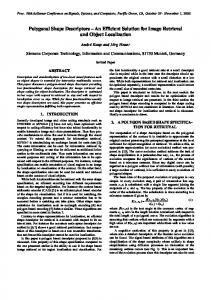
Figure 1: The Cassini spacecraft model consisting of 349,281 faces and 127 objects. Using LODs created by GAPS, we achieve a 3.5 times average speedup when viewing this model with little loss in image quality. When the whole model is in view, we achieve a 10 times speedup, assuming we allow 6 pixels of error on a 250 MHz R4400 SGI InfiniteReality in a 1280x1000 window. GAPS created the LODs for all objects of this model in 274 seconds on a 195 MHz R10000 SGI InfiniteReality2. and drastic approximations of objects in the scene. Previous algorithms cannot simultaneously satisfy all these criteria.
1.1
Main Contribution
In this paper, we present an algorithm to automatically simplify polygonal objects. Some of the main features of our approach are: • General: Polygonal objects often contain modeling errors such as cracks, non-manifold vertices and edges, coincident polygons, and t-joints. In order to enhance visual realism, objects usually include surface attributes such as textures, colors, and normals. We have demonstrated our algorithm on a variety of objects with these properties, including radiositized scenes, textured and scanned meshes, CAD environments, and terrain models. • Automatic: Often it is necessary to simplify a large polygonal scene, containing numerous objects. It is tedious for a user to specify parameters to guide the simplification process for each object. Our algorithm runs in a batch mode, without user intervention. It also produces error bounds on the simplified object, useful for automatically determining switching distances between LODs used by rendering
• • •
•
1.2
systems. These error bounds are sensitive to both the geometry and the surface attributes of the simplified object. Drastic: The algorithm can drastically simplify a polygonal object such that a user can target a number of polygons and the algorithm produces an appropriate simplification. High Quality: The algorithm constructs high quality approximations of an object, preserving its basic shape, main features, and surface appearance. Topology-simplifying: In order to achieve high quality and drastic simplifications of an arbitrary group of polygons, the algorithm joins unconnected regions of the object or changes its genus by closing holes. Efficient: The algorithm simplifies quickly. On average, we are able to perform 500 vertex merge operations per second on a 195 MHz R10000 SGI InfiniteReality2.
Organization
The rest of the paper is organized in the following manner. We survey related work in polygonal simplification in Section 2. Terminology used in the paper is described in Section 3. We present our algorithm in Section 4. Implementation details are described in Section 5 while our results are presented in Section 6. We compare our approach to other simplification algorithms in Section 7.
2
If p = [a b c d]T represents the plane defined by the equation ax + by + cz + d = 0 where a2 + b2 + c2 = 1, then this algorithm associates with p a fundamental error quadric Kp where
Kp = pp
PREVIOUS WORK
Numerous methods have been proposed to produce simplified versions of polygonal objects. Most of the earlier work in polygonal simplification focuses on generating levels of detail, or LODs, of a given object. Different algorithms vary in terms of quality of approximation, efficiency, simplification operations, and assumptions on the input model. The common set of geometric operations correspond to vertex removal and retriangulating holes [Bajaj96, Kalvin94, Schroeder92, Soucy96, Turk92], edge collapses [Cohen97, Cohen98, Guéziec95, Hoppe93, Hoppe96, Kobbelt98, Lindstrom98, Ronfard96], and triangle removal [Hamann94]. Many of the earlier algorithms assume that the input model is a manifold and represented as a valid mesh. Other algorithms include those based on multiresolution wavelet analysis [Eck95], simplification envelopes [Cohen96], and progressive meshes [Hoppe96]. All of these algorithms have been designed for manifold surfaces. For general polygonal models, algorithms based on vertex clustering have been proposed by [Low97, Luebke97, Rossignac93, Schaufler95]. These algorithms allow topological changes as the model is simplified. [Schroeder97] presents a topology modifying decimation algorithm that can guarantee a requested reduction level. [He95] and [El-Sana96] demonstrate algorithms for controlled simplification of genus of polyhedral objects. For a more thorough survey of simplification algorithms, consult [Heckbert97].
2.1
Distance threshold used for selecting virtual edges τ α, α−, α+ An amount of surface area Error of an area weighted error quadric of vertex v ∆(v) Surface area associated with a vertex’s quadric S(v) GAPS geometric error at vertex v Γ(v) a0, a1, … Weights corresponding to surface areas Squared error of point p in point cloud c Π(p) c0 Surface area associated with point cloud c Average error of point p in point cloud c Α(p) GAPS normal error at vertex v Ν(v) C(v) GAPS color error at vertex v GAPS texture coordinate error at vertex v Τ(v) GAPS unified object space error at vertex v Ε(v) Table 1: Brief descriptions of symbols used in this paper.
Surface Simplification Using Quadric Error Metrics [Garland97a]
This algorithm, similar to [Ronfard96], tracks an error bound by associating each vertex with a set of planes. However, it approximates the set of planes using a symmetric matrix called an error quadric. It uses the vertex merge operation to simplify, so it is able to join unconnected regions of an object. It is fast and produces high quality results, but is fairly memory intensive.
T
a 2 ab = ac ad
ab
ac
ad
b bc
bc 2 c
bd cd
bd
cd
d
2
2
To find the squared distance from a plane p to a point v = [vx vy vz 1], the algorithm uses the quadric form vTKpv. Error quadrics can represent a union of two quadrics, or a set of planes, simply by adding their corresponding matrices. Each vertex v has an associated error quadric Q that may consist of several fundamental error quadrics summed together. The error at a vertex v with quadric Q is defined to be ∆(v) = vTQv. This value represents the sum of squared distances between the vertex v and all of the planes associated with the quadric Q. Given a quadric Q, an optimal vertex position v can usually be calculated which minimizes ∆(v). This calculation involves inverting a matrix that is defined by Q. Initially, the error quadric of each vertex consists of planes of the vertex’s adjacent faces plus planes to preserve sharp edges. A vertex’s adjacent faces are any faces that are incident to that vertex. Candidates for vertex merging include vertices that share an edge or two vertices that are within an optional user-specified distance threshold τ. When vertices do not share an edge, but are a candidate pair, we say they share a virtual edge. For each candidate merge, the optimal vertex position and total error are calculated. The candidates are inserted into a heap, sorted by increasing error. The vertex merge on top of the heap is performed, and the error quadric of the new vertex becomes the sum of the quadrics of the merged vertices. The error of candidate pairs in the local neighborhood of the merge must be updated. The algorithm continues to merge vertices until a target number of polygons is achieved.
3
TERMINOLOGY
There are several symbols used in this paper and their meanings are briefly described in Table 1. Note that subscripts n, c, and t refer to normal, color, and texture coordinate point clouds respectively. For example, cn0 refers to the surface area associated with normal point cloud cn and Αt(p) is the average error of point
(a)
(a) τ =
(b) τ =
(b) τ =
(c) τ = Figure 2: The problem with specifying a single distance threshold τ. (a) The top pair of rectangles is a scaled copy of the bottom pair. What is a good τ for this model? (b) Grey edges are real edges and black edges are virtual edges. There are not enough virtual edges when τ is the shortest distance between the bottom rectangles. (c) There are too many virtual edges when τ is the shortest distance between the top rectangles.
p with respect to the texture coordinate point cloud ct. Point clouds are described in detail in Section 4.3.3.
4
GAPS
We introduce a new simplification algorithm, called General and Automatic Polygonal Simplification, or GAPS, for short. We use the quadric error metric and extend upon it in three ways to meet our simplification goals. • We automatically and adaptively select the distance threshold τ in order to simplify topology efficiently. • We do not allow vertex merges that change the local surface area greatly in relation to τ through the use of surface area preservation. • Surface attributes are updated during the simplification process and are incorporated into an object space error metric. Like other algorithms, GAPS triangulates input objects as a preprocess step.
4.1
Automatic and Adaptive Selection of Distance Threshold
As stated in Section 2, [Garland97a] allows the user to specify a distance threshold τ that determines all virtual edge pairs for the rest of its execution. If two vertices are within this distance τ, then the virtual edge between them is inserted into the heap of candidate edges. However, we would like an algorithm that runs without user intervention. Given this goal, asking the user to input a distance threshold for each object in a large model is not acceptable. Furthermore, for some polygonal objects, specifying a single τ will result in too little or too many virtual edge candidates (see Figure 2). If there are not enough virtual edge candidates, the quality of the simplified object may suffer. If
(c) τ =
Figure 3: Simplification using an adaptive distance threshold. (a) The initial value of τ is the shortest distance between the bottom pair of rectangles. The two pairs of white vertices joined by virtual edges are merged together. (b) τ grows. The pairs of white vertices joined by real edges are next to be merged, making the bottom rectangles disappear. (c) Again, τ grows. Note how the top pair of rectangles is being simplified in the same fashion as the vanished bottom pair. there are too many candidates, then the algorithm will execute slowly. Therefore, the process of manually picking a good τ is a difficult one. GAPS does not use a single distance threshold. Instead, τ starts at a very small value and grows during the simplification process. Determination of the initial value τ and its subsequent growth happen automatically, without user intervention. The basic idea of the method is illustrated in Figure 3. In order to find virtual edges within the distance threshold efficiently, we must partition the object space to avoid O(n2) growth. Given the bounding box of the object, we partition it uniformly into cubes of length τ. To determine vertices within τ from a specific vertex, we check only vertices that lie in the same cube or corner-adjacent cubes of the vertex. However, when τ is small, the number of cubes is too large to fit into memory. Therefore, our method represents this uniform grid by a hash table. The initial guess for τ assumes that the vertices are distributed uniformly throughout the bounding box of the object. Using this starting value, we partition space into cubes of length τ. If an insertion of a vertex into the hash table causes a bin to contain more than a constant number of vertices, then we deem τ to be invalid. This constant could be any reasonable value but we used 10 for all results in this paper. If τ is not valid, then we halve τ and check its validity again. Vertex pairs that are within the distance threshold τ are flagged as local pairs, whether they represent real or virtual edges. If the error (described in Section 4.3) associated with the next pending vertex merge is greater than τ or there are no local pairs remaining, then τ doubles. When τ grows, a new hash table must be created and remaining vertices re-inserted.
(a)
(b)
τ=
(c)
τ=
Figure 4: Illustration of surface area preservation on a simple model. (a) The original model. (b) Simplification without surface area preservation. Gray edges are real edges and black edges are virtual edges. The white pair of vertices is next to be merged. The order of the vertex merges is based solely on the distance between pairs, causing the two rectangles to vanish independently. (c) Using surface area preservation, many of the merges in (b) are not allowed. The two rectangles join and produce a higher quality simplification.
4.2
Surface Area Preservation
Normally, vertex merges are performed in order of increasing error based on the error quadrics at each vertex. Although we feel these quadrics provide a good approximation of geometric error at vertices, there are some cases where merging in order of increasing error leads to poor simplification choices. Because error quadrics measure distance error at vertices, pairs that are
(a)
τ
(b) Figure 5: An example of surface area preservation. On the left, the pairs of white vertices are potential merge candidates. In the middle, the shaded area represents the surface area change due to the merge. On the right, the shaded area has formed a circle with equivalent surface area. (a) This operation is not allowed since the area it changes shown in the top circle is greater than α = πτ2, the middle circle. However, if τ doubles, then this operation becomes legal. (b) The merge is allowed because the area in the bottom circle is less than the middle circle.
joined by short edges will most likely be merged first. However, if the merging of two vertices changes the local surface area drastically, the visual results are unappealing. For example, an isolated long and skinny triangle will disappear if any of its edges collapse. However, this disappearance is very noticeable even though the quadric error metric returns a small error for the operation (see Figures 8-9). Through the use of surface area preservation, vertex merges that increase or decrease the local surface area greatly in relation to τ are not allowed. In many cases, this technique allows GAPS to join unconnected regions of objects, thereby producing higher quality simplifications. A demonstration of surface area preservation on a simple model is shown in Figure 4. To determine whether a vertex merge changes the local surface area drastically relative to τ, we first sum the surface area of each face that is adjacent to at least one of the vertices involved − in the merge. This sum, α , is the local surface area before the merge operation executes. To calculate α+, the local surface area after the merge, we sum the surface areas of any adjacent faces of the new merged vertex. Besides being the distance threshold for virtual edge selection, τ also determines the allowable change in surface area during a merge. Therefore, τ can be thought of as the current scale at which GAPS is operating. The allowable change in surface area is defined to be α = πτ2, i.e., the area of a circle of − radius τ. If the change in surface area α+ − α is greater than α, then the merge is not allowed. If τ grows (see Section 4.1), previously disallowed merge operations may become legal. Intuitively, surface area preservation temporarily blocks merge operations that cause isolated collections of polygons to disappear. It thereby promotes the merging of unconnected regions of an object in order to produce higher quality simplifications. Figure 5 shows an example of determining whether vertex merges are allowed according to surface area preservation.
4.3
Attribute Handling and a Unified Error Metric
Many polygonal objects contain geometry as well as surface attributes such as normals, colors, and texture coordinates. Handling these attributes during simplification is an important, but difficult problem that involves many perceptual issues that are not well understood. We present a simple, efficient, and intuitive method that provides a reasonable object space error metric. Each type of error, whether it is due to geometry, normals, colors, or texture coordinates, is independently tracked during simplification.
4.3.1
Interpolating Attributes
We decouple geometric and attribute error and use quadric error metrics for determining merged vertex positions. Besides locating new vertices, we update any vertex attributes that are adjacent to the edge being collapsed. To determine the new attribute for a merged vertex, we project the vertex onto its local geometry assuming that the merge has not yet occurred. Limiting our search to this local geometry, we find the nearest face and nearest point on this face from the new vertex. Using this nearest point, we interpolate the original attributes to obtain the new interpolated attribute. If there are attribute discontinuities at a merged vertex, the process is similar but more than one pair of attributes are merged.
4.3.2
Geometric Error
We handle geometric error by associating with each vertex an error quadric. Initially, we insert the planes of a vertex’s adjacent faces, weighted by the surface area of each face, into the vertex’s error quadric. In addition, we keep track of the amount of surface area involved in each quadric. Whenever we merge vertices, the error quadric of the new vertex is simply the sum of the error quadrics of the merged vertices. The surface area involved in the new quadric is the sum of the surface areas involved in the merged quadrics. If v = [x y z] is the position of a vertex, let ∆(v) be the area-weighted sum of squared distances between the vertex and its planes. S(v) is defined to be the total surface area involved in the quadrics at the vertex. We define the final geometric error as Γ( v) =
∆(v) S(v )
Intuitively, this error approximates the average deviation error of the vertex from its set of planes.
4.3.3
Attribute Error Via Point Clouds
We opted to use a very simple, efficient, but approximate method for computing error in attribute space. We independently track different types of attribute error due to normals, colors, and texture coordinates, by using point clouds. A point cloud is a collection of points enabling the efficient calculation of the sum of squared distances between a specified point and all the points in the cloud. Assume we are in 3-dimensional space, and there are n points p0, p1, p2, …, pn − 1, with corresponding weights a0, a1, a2, …, an − 1, in the cloud. Each point has coordinates pi = [xi yi zi], and p = [x y z] is the point of interest. Then the weighted sum of squared distances from the specified point to the cloud of points is
n −1
Π(p ) = ∑ ai p − pi
2
i=0
=
2 2 2 ∑ ai [( x − xi ) + ( y − yi ) + (z − zi ) ] n −1 i =0
For each point cloud, we store a vector c = [c0 c1 c2 c3 c4] where
c0 =
n −1
∑ ai , i =0
n −1
n −1
n −1
i =0
i =0
c1 = ∑ ai xi , c2 = ∑ ai yi , c3 = ∑ ai zi , and i=0
n −1
(
c4 = ∑ ai xi 2 + yi 2 + zi 2 i =0
)
Using the vector c, we can quickly calculate Π(p) by
(
)
Π(p ) = c0 x 2 + y 2 + z 2 − 2(c1 ⋅ x + c2 ⋅ y + c3 ⋅ z ) + c4
We define the error of a point p in respect to a point cloud c as Α(p ) =
Π(p ) c0
Intuitively, Α(p) approximates the average error at point p with respect to cloud c. This representation for point clouds makes combining clouds very efficient. Suppose we have two clouds c0 and c1 and we create a new cloud of points c that contains all points from both clouds. Then c = c0 + c1. It can be shown that the minimum of Π(p) with respect to a cloud c occurs when p is the weighted average of all the points included in the cloud. Every vertex, besides containing an error quadric to measure geometric deviation, also keeps track of a point cloud per type of attribute used. Thus, if an object used normals, colors, and texture coordinates, the vertex would contain an error quadric, a normal point cloud, a color point cloud, and a texture coordinate point cloud. To initialize a particular point cloud, we first calculate an average attribute for that vertex based on its local surface attributes. We insert this average attribute, weighted by the surface area of the vertex’s adjacent faces, as the only point in the cloud initially. When two vertices merge, we combine their error quadrics as well as their attribute point clouds. Since we initially store an average attribute in a point cloud, we do lose attribute discontinuity information at vertices. However, we accept this approximation for reasons of efficiency and the fact that attribute discontinuities are handled in part by the quadric error metric (see Section 5.2). 4.3.3.1 Normal Error Normal point clouds consist of three-dimensional points, as in the example point cloud description above. To find the error in normal space due to two vertices merging, we first combine the normal point clouds. Ideally, the interpolated normal resulting from this merge would be used to determine the error in normal space using the new normal point cloud. However, the operation of interpolating the normals (see Section 4.3.1) is too expensive to be performed every time we rate the quality of a merge candidate. Therefore, we use an efficient, but very approximate method in its place. For a combined cloud, we assume that the interpolated normal will be the one that creates the least amount of normal space error. In order to approximate how much error in object space is due to normals, we use the degree of error in normal space plus the amount of surface area this error affects. Since the Euclidean distance between two normals on the unit sphere can be at most 2,
r
(a)
(b)
(c)
Figure 6: Conversion of normal space error to object space error. (a) The two white vertices are next to be merged. The average normals at the vertices are shown, depicting their initial normal point clouds. (b) The combined normal point cloud when the vertex pair is merged. The gray point represents the point of minimum error according to this point cloud. (c) The surface area of the adjacent faces of the two vertices being merged form the shaded circle above. This area is modified by the degree of error in normal space to obtain the final affected surface area, represented by the smaller circle with radius r. r is defined as the object space error due to normals. we halve the average error Αn(p) of the normal point cloud cn. This normalized value is within the range 0 to 1, indicating the degree of error in normal space. The more surface area this normal error affects, the more visual error there will be due to simplification. Based on this idea, we transform normal error into object space by using a simple and approximate technique. Associated with the point cloud cn is cn0, the sum of all weights involved in the point cloud. However, these weights equal the total surface area represented by this merged vertex. Therefore, we use cn0 as the total surface area in which the error occurs, and the normalized error as the degree of error across this area. Suppose pn is the minimal error point for point cloud cn. Then, the transformation from error in normal space to error in object space for a vertex v with normal point cloud cn is
Α n (p n ) Ν(v ) =
2
π
⋅ cn 0
=
Α n (p n ) ⋅ cn 0 2π
Intuitively, this equation starts with surface area cn0 and multiplies it by the degree of normal error. Next, it finds the radius of the circle whose surface area is equivalent to this multiplied area. This radius is defined to be the object space error due to normals (see Figure 6). 4.3.3.2 Color Error We assume that colors have four components: red, green, blue, and alpha and that these components are within the range 0 to 1. Therefore, we must use four-dimensional point clouds to keep track of color. We represent a four-dimensional point cloud in almost the same way as a three-dimensional one, except we must keep track of six values, rather than five. Since the Euclidean distance between two colors in color space can be at most 2, we normalize color error by this value. Suppose pc is the minimal error point for color point cloud cc. Then, the transformation from error in color space to error in object space for a vertex v with normal point cloud cc is C(v ) =
Αc (p c ) ⋅ cc0 2π
4.3.3.3 Texture Coordinate Error We assume two-dimensional texture coordinates for our polygonal objects, so we use two-dimensional point clouds to track texture coordinate error. We represent a two-dimensional point cloud in almost the same way as a three-dimensional one, except we keep track of four values, rather than five. Our technique relies on using bounded attribute values and thus we assume that each dimension of a texture coordinate is within range 0 to 1. Since the Euclidean distance between two texture coordinates in texture coordinate space can be at most √2, we normalize texture coordinate error by this value. Suppose pt is the minimal error point for texture coordinate point cloud ct. Then, the transformation from error in attribute space to error in object space for a vertex v with texture coordinate point cloud ct is Τ(v ) =
4.3.4
2 Α t (p t ) ⋅ ct 0 2π
Unified Error Metric
Therefore, at a vertex v with normal point cloud cn, color point cloud cc, and texture point cloud ct, we define the average error to be a weighted average of all of its component errors. In other words, Ε (v ) =
S(v ) ⋅ Γ (v ) + cn 0 ⋅ Ν(v ) + cc 0 ⋅ C(v ) + ct 0 ⋅ Τ(v ) S(v ) + cn 0 + cc 0 + ct 0
We use Ε(v) to determine the best candidate vertex pair to merge. To estimate the maximum error over an entire object, we take a weighted average of all vertex errors and multiply by a constant. By applying our technique on a number of models, we have found that a constant of 10 works well. Using this estimate, we automatically calculate LOD switching distances to be used in rendering systems.
5
IMPLEMENTATION
We have implemented GAPS using C++, GLUT, and OpenGL. The code is portable across PC and SGI platforms. Our algorithm has produced good results on a variety of datasets including scanned, terrain, radiositized, and CAD objects.
5.1
Generality and Robustness
GAPS handles all polygonal objects, whether they are manifold meshes or unorganized lists of polygons. As a preprocess, objects are triangulated and then represented by sharing vertices and calculating normals. Although these operations are not necessary for GAPS, it can take advantage of more topology information to produce better simplifications more efficiently. Objects consist of vertices, triangular faces, vertex attributes, and face attributes. Vertex attributes are colors, normals, and texture coordinates. Face attributes are colors, materials, and textures. This categorization is equivalent to the one described in [Hoppe96] and [Hoppe98], except that Hoppe names them scalar and discrete attributes respectively. We use a simple internal representation for objects where faces consist of three corners. Each corner has a pointer to a vertex and a vertex attribute. Vertices consist of a three-dimensional point plus a list of pointers to adjacent faces. Almost any polygonal model can be described with this representation. In practice, we have applied
Object
Verts
Tris
QSlim time (secs.)
QSlim time using τ (secs.)
GAPS not using τ (secs.)
GAPS (secs.)
Rotor
2328
4736
1.45
1.59
1.56
2.19
Head
4925
9580
2.89
3.63
3.51
4.63
Chamber
5685
10423
9.48
17.09
3.50
6.98
Econ
10032
23556
7.61
68.60
7.72
25.22
Bunny
34834
69451
27.23
30.15
27.91
38.72
ShDiv
65245
141180
42.02
170.55
47.35
147.49
Sierra
81920
162690
67.18
182.54
60.41
193.09
Table 2: Simplification timings for various models running on an SGI with 195 MHz R10000 processors and 2 gigabytes of main memory. To choose τ for QSlim, we used 1% of the maximum bounding box dimension of the object being simplified. The “GAPS not using τ” column signifies that attribute error was handled, but that no virtual edges were considered and no surface area preservation was performed. our algorithm to large CAD models composed of non-manifold and degenerate geometry.
5.2
Discontinuities
As in [Garland97a], additional perpendicular constraint planes are added to the error quadrics of vertices that lie on boundary edges, or places where there is a geometric discontinuity. Unlike [Garland97a] which assigns a large penalty to these planes, we weight them using the surface area of the face that contains the boundary edge. Similarly, if there is a vertex or face attribute discontinuity occurring at an edge, constraint planes are inserted as if the edge was a boundary edge. It has been our experience that these extra constraint planes work very well at preserving both geometric and attribute discontinuities during simplification.
5.3
Main Loop
After initialization, the main loop of GAPS executes as follows: • Check if τ needs to be doubled. Doubling occurs when either there are no more local pairs in the heap or when the pair on top of the heap has error greater than τ. When we double τ, we must recalculate the error and legality of all active pairs. • Extract the top pair from the heap. Delete the two vertices in the pair from the hash table with grid cells of size τ. Insert the new vertex into the hash table to find virtual edges incident to it. Add quadrics and point clouds of the two vertices and store this information with the new vertex. • Update or delete pairs affected by the vertex merge. • Repeat until a specified number of vertices or faces remain, or an error threshold has been reached.
6
RESULTS
In this section, we highlight the performance of GAPS on various polygonal models.
6.1
Execution Speed
All of our timing results were gathered on a 195 MHz R10000 SGI InfiniteReality2 with 2 gigabytes of main memory. Table 2 shows timing comparisons between GAPS and QSlim, Michael
Garland’s publicly available simplification code [Garland97b]. These timings include both setup time, such as initializing the error quadrics and determining virtual edge pairs, plus simplification time. For QSlim, we specified options –m (preserve mesh quality), –a (area weight error quadrics), and –B 1000 (penalize boundary edges with weight 1000). Assuming these settings, QSlim runs about twice as fast as GAPS on average. The Bunny object is the traditional scanned mesh from Stanford University, Head is a texture-mapped scanned mesh (see Plate 4), and Sierra is a terrain model (see Plate 3). If the user knows that an object consists of one connected mesh with no holes and genus zero, then there is little point in using a distance threshold for the selection of virtual edges. Therefore, there is an option in GAPS to turn off virtual edge selection. The timings for GAPS using this option are shown in Table 2 as well. Even though GAPS is still handling attributes, the results are comparable to QSlim. Only objects that contain disconnected regions of geometry in close proximity benefit from using τ. Rotor, Econ, ShDiv, and Chamber (see Figures 8-9 and Plates 1-2) all fall under this type of object. Rotor, Econ, and ShDiv are CAD models while Chamber is a radiositized object. Even if we specify a small τ for QSlim, then GAPS, with its adaptive distance threshold, outperforms QSlim on Econ and ShDiv.
6.2
Memory Usage
GAPS needs to store extra information at vertices and faces during simplification. Error quadrics, point clouds, and their respective total surface areas are stored at each vertex. Each face has an associated plane and surface area, used to make GAPS more efficient when checking for mesh inversion and surface area preservation. We also store a hash table that contains pointers to vertices and a heap of candidate pairs. Therefore, this algorithm is fairly memory intensive. Assuming we track all attributes, then each vertex requires 26 and each face requires 5 additional floating point values of storage.
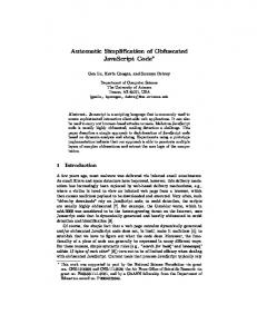
Figure 7: A close up view of the torpedo room model consisting of 883,537 faces and 356 objects. Using LODs created by GAPS, we achieve a 5 times average speedup when viewing this model with little loss in image quality. When the whole model is in view, we achieve a 10 times speedup, assuming we allow 10 pixels of error on a 250 MHz R4400 SGI InfiniteReality in a 1280x1000 window. GAPS created the LODs for all objects of this model in 834 seconds on a 195 MHz R10000 SGI InfiniteReality2.
6.3
Viewing Large Polygonal Environments
GAPS can be used to automatically create LODs for large polygonal environments, consisting of hundreds of objects. For each object in the scene, we create a series of LODs. Each LOD for an object has an estimated maximum object space error that is automatically calculated by GAPS (see Section 4.3). By projecting this error onto the view plane, we are able to find the LOD’s screen space error. By taking into account the dimensions of the viewing window in pixels, we can transform this screen space error into pixel error. If this pixel error is less than a userspecified pixel error, then the LOD is an acceptable representation for the object at the given distance from the viewer. Therefore, we are able to render the coarsest LOD possible that still meets the user specified pixel error requirement. This method of rendering is used in nearly all scene graph visualizations involving LODs [Cohen96, Schneider94]. By using LODs produced by GAPS, we are able to accelerate the rendering of large complicated CAD environments such as the ones shown in Figures 1 and 7. On average, we experience a 3.5 to 5 times speedup when viewing these models with little loss in image quality. This difference in rendering speed allows our viewing sessions to run at interactive frame rates.
7
COMPARISON
In this section, we first compare simplification algorithms that lie in the domain of topological simplification followed by ones that handle surface attributes. [Popovic97] presents an interesting
topological simplification algorithm to produce a progressive simplicial complex. This method is elegant, but is too slow for our needs and uses primitives other than polygons. [Rossignac93] and [Low97] use vertex clustering to topologically simplify models efficiently and robustly. Although these algorithms are extremely quick, the quality of their approximations can be poor on some models. [He95] uses a voxel-based approach but control over the degree of simplification is difficult. [El-Sana97] controls the genus of an object and [Schroeder97] simplifies to any target number of faces quickly, but both are unable to join unconnected regions of an object. Increasingly more algorithms are addressing surface attributes during the simplification process. [Hoppe96] includes scalar and discrete attributes in the energy function the algorithm tries to minimize. However, this method is slow in practice. [Cohen98] uses texture and normal maps for appearance preserving simplification. Although this algorithm is elegant, it requires a surface parameterization and uses normal mapping that is not widely available in current hardware. Garland and Heckbert extend their original algorithm in [Garland98] to handle surface attributes. They ignore topological simplification and use a higher dimensional error quadric to track geometric and surface attribute error together. However, this higher dimensional space is difficult to understand and the error at vertices does not correspond to a distance in object space. We efficiently decouple surface attributes from geometry and use a unified error metric that aids automatic selection of switching distances for LODs of an object. [Cignoni98] propose an efficient algorithm that creates surface attributes for a simplified mesh by sampling the original object. However, this method requires the storage of potentially large texture maps for each level of detail desired.
8
SUMMARY AND FUTURE WORK
We present a new topological simplification algorithm that is general, automatic, efficient, handles surface attributes, produces high quality approximations, and merges unconnected regions of objects using an adaptive distance threshold and surface area preservation. It uses an object space error metric that aids the calculation of switching distances for LODs. The algorithm appears to work well on all types of models, ranging from smooth surfaces to disjoint pipes. There are many avenues for future work. Our approach for attribute handling is very approximate and could be improved. We would like to see if the work of [Lindstrom98] could be used to lessen the memory consumption of GAPS. Furthermore, it would be interesting to integrate the progressive mesh work of [Hoppe96] with the topological simplifications produced by GAPS. The techniques for topological simplification might also be extended to models composed of spline primitives [Gopi98]. Now that more simplification algorithms are handling surface attributes, it would be nice to have a comparison tool that measures the quality of each algorithm’s output. This tool would necessarily use a new error metric involving both geometry and attributes. Finally, GAPS simplifies individual objects one at a time. For example, the pipes in Figure 8 are considered one object. However, large polygonal environments are usually broken into numerous objects, represented by different nodes in a scene graph. The standard method that we use in Section 6.3 is to create a series of LODs for each object independently. Therefore, even though two objects may be in close proximity, GAPS will never merge disconnected regions between the pair because it
simplifies them separately. [Erikson98] describes a promising approach for hierarchically combining objects for simplification.
9
ACKNOWLEDGMENTS
The Cassini spacecraft model is courtesy of Stephen Wall, Gary Clough, Don Jacob, and JPL. The Rotor object is courtesy of the Alpha_1 Project at the University of Utah. The Head model is courtesy of Hans Weber, created using InSpeck Inc. software. The Chamber model was created by Mike Goslin and David Luebke. The Econ and ShDiv objects are courtesy of James Close and Combustion Engineering, Inc. The scanned Bunny object is courtesy of Stanford University. The Sierra terrain model is courtesy of Herman Towles and Sun Microsystems. The torpedo room model is courtesy of Greg Angelini, Jim Boudreaux, Ken Fast, and Electric Boat, a subsidiary of General Dynamics. This work was supported in part by an Alfred P. Sloan Foundation Fellowship, ARO Contract DAAH04-96-1-0257, Honda, Intel Corp., NIH/National Center for Research Resources Award 2P41RR02170-13 on Interactive Graphics for Molecular Studies and Microscopy, NSF grant CCR-9319957 and Career Award, an ONR Young Investigator Award, the NSF/ARPA Center for Computer Graphics and Scientific Visualization, and NCAA Graduate, NSF Graduate, and Intel Fellowships.
10 REFERENCES [Bajaj96]
[Cignoni98]
[Clark76] [Cohen96]
[Cohen97]
[Cohen98]
[Eck95]
[El-Sana97]
[Erikson98]
[Garland97a]
[Garland97b] [Garland98]
[Gopi98]
[Guéziec95]
[Hamann94] [He95]
Bajaj, C., and Schikore. D. “Error-Bounded Reduction of Triangle Meshes with Multivariate Data,” SPIE, vol. 2656, 34-45, 1996. Cignoni, P., Montani, C., Rocchini, C., and Scopigno, R. “A General Method for Preserving Attribute Values on Simplified Meshes,” IEEE Visualization ’98 Proceedings, 59-66, 1998. Clark, J. “Hierarchical Geometric Models for Visible Surface Algorithms,” Communications of the ACM, 547-554, 1976. Cohen, J., Varshney, A., Manocha, D., Turk, G., Weber, H., Agarwal, P., Brooks, F., and Wright, W. “Simplification Envelopes,” Computer Graphics (SIGGRAPH ’96 Proceedings), 119-128, 1996. Cohen, J., Manocha, D., and Olano, M. “Simplifying Polygonal Models Using Successive Mappings,” IEEE Visualization ’97 Proceedings, 395-402, 1997. Cohen, J., Olano, M., and Manocha, D. “Appearance-Preserving Simplification,” Computer Graphics (SIGGRAPH ’98 Proceedings), 115-122. Eck, M., DeRose, T., Duchamp, T., Hoppe, H., Lounsbery, M., and Stuetzle, W. “Multiresolution Analysis of Arbitrary Meshes,” Computer Graphics (SIGGRAPH ’95 Proceedings), 173-182, 1995. El-Sana, J., and Varshney, A. “Controlled Simplification of Genus for Polygonal Models,” IEEE Visualization ’97 Proceedings, 403410, 1997. Erikson, C., and Manocha, D. “Simplification Culling of Static and Dynamic Scene Graphs,” UNC Chapel Hill Computer Science Technical Report TR98-009, 1998. Garland, M., and Heckbert, P. “Surface Simplification Using Quadric Error Metrics,” Computer Graphics (SIGGRAPH ’97 Proceedings), 209-216, 1997. Garland, M. “QSlim Simplification Software,” http://www.cs.cmu.edu/~garland/quadrics/qslim.html, 1997. Garland, M., and Heckbert, P., “Simplifying Surfaces with Color and Texture using Quadric Error Metrics,” IEEE Visualization ’98 Proceedings, 263-269, 1998. Gopi, M. and Manocha, D., “A Unified Approach for Simplifying Polygonal and Spline Models,” IEEE Visualization ’98 Proceedings, 271-278, 1998. Guéziec, A. “Surface Simplification with Variable Tolerance,” Second Annual Intl. Symp. On Medical Robotics and Computer Assisted Surgery (MRCAS ’95), 132-139, 1995. Hamann, B. “A Data Reduction Scheme for Triangulated Surfaces,” Computer-Aided Geometric Design, 197-214, 1994. He, T., Hong, L., Kaufman, A., Varshney, A., and Wang, S. “Voxel-Based Object Simplification,” IEEE Visualization ’95 Proceedings, 296-303, 1995.
[Heckbert94] [Heckbert97]
[Hoppe93]
[Hoppe96] [Hoppe97]
[Hoppe98] [Kalvin94]
[Kobbelt98]
[Lindstrom98]
[Low97]
[Luebke97]
[Popovic97]
[Ronfard96]
[Rossignac93]
[Schaufler95]
[Schneider94]
[Schroeder92]
[Schroeder97] [Soucy96]
[Turk92]
Heckbert, P., and Garland, M. “Multiresolution Modeling for Fast Rendering,” Graphics Interface ’94 Proceedings, 43-50, 1994. Heckbert, P., and Garland, M. “Survey of Polygonal Surface Simplification Algorithms,” Draft of Carnegie Mellon University Computer Science Technical Report, 1997. Hoppe, H., DeRose, T., Duchamp, T., McDonald, J., and Stuetzle, W. “Mesh Optimization,” Computer Graphics (SIGGRAPH ’93 Proceedings), 19-26, 1993. Hoppe, H. “Progressive Meshes,” Computer Graphics (SIGGRAPH ’96 Proceedings), 99-108, 1996. Hoppe, H. “View-Dependent Refinement of Progressive Meshes,” Computer Graphics (SIGGRAPH ’97 Proceedings), 189-198, 1997. Hoppe, H. “Efficient Implementation of Progressive Meshes,” Computers & Graphics Vol. 22 No. 1, 27-36, 1998. Kalvin, A., and Taylor, R. “Superfaces: Polyhedral Approximation with Bounded Error,” SPIE Medical Imaging ’94 Proceedings, vol. 2164, 1994. Kobbelt, L., Campagna, S., and Seidel, H-P. “A General Framework for Mesh Decimation,” Graphics Interface ’98 Proceedings, 43-50, 1998. Lindstrom, P., and Turk,G. “Fast and Memory Efficient Polygonal Simplification,” IEEE Visualization ’98 Proceedings, 279-286, 1998. Low, K., and Tan, T. “Model Simplification Using VertexClustering,” Symposium on Interactive 3D Graphics ’97 Proceedings, 75-82, 1997. Luebke, D., and Erikson, C. “View-Dependent Simplification of Arbitrary Polygonal Environments,” Computer Graphics (SIGGRAPH ’97 Proceedings), 199-208, 1997. Popovic, J., and Hoppe, H. “Progressive Simplicial Complexes,” Computer Graphics (SIGGRAPH ’97 Proceedings), 217-224, 1997. Ronfard, R., and Rossignac, J. “Full-range Approximation of Triangulated Polyhedra,” Computer Graphics Forum (Eurographics ’96 Proceedings), 67-76, 1996. Rossignac, J., and Borrel, P. “Multi-Resolution 3D Approximations for Rendering Complex Scenes,” Geometric Modeling in Computer Graphics, 455-465, 1993. Schaufler, G., and Sturzlinger, W. “Generating Multiple Levels of Detail from Polygonal Geometry Models,” Eurographics Workshop on Virtual Environments ’95, 33-41, 1995. Schneider, B., Borrel, P., Menon, J., Mittleman, J., and Rossignac, J. “Brush as a Walkthrough System for Architectural Models,” Fifth Eurographics Workshop on Rendering, 389-399, 1994. Schroeder, W., Zarge, J., and Lorensen, W. “Decimation of Triangle Meshes,” Computer Graphics (SIGGRAPH ’92 Proceedings), 65-70, 1992. Schroeder, W. “A Topology Modifying Progressive Decimation Algorithm,” IEEE Visualization ’97 Proceedings, 205-212, 1997. Soucy, M., and Laurendeau, D. “Multi-Resolution Surface Modeling Based on Hierarchical Triangulation,” Computer Vision and Image Understanding, vol. 63, 1-14, 1996. Turk, G. “Re-Tiling Polygonal Surfaces,” Computer Graphics (SIGGRAPH ’92 Proceedings), 55-64, 1992.
Figure 8: Econ LODs. The top row shows LODs created using the quadric error metric but no distance threshold and no surface area preservation. Note how the pipes thin during simplification. The LODs in the bottom row were created using GAPS. The pipes join together at the latter stages of simplification, preserving more of the surface area of the object. These LODs from left to right have approximately 23,556 faces (the original object), 5,888 faces, 1,470 faces, 368 faces, and 90 faces.
Figure 9: ShDiv LODs. The top row shows LODs created using the quadric error metric but no distance threshold and no surface area preservation. The LODs in the bottom row were created by GAPS. In the latter stages of simplification, the bottom row retains more of the overall structure of the pipes than the top row. The LODs from left to right have approximately 141,180 faces (the original object), 17,644 faces, 2,202 faces, and 272 faces.
Plate 1: LODs for the Chamber object from a top-down view. The top row shows LODs created when attribute error is ignored. Note how the shadow and lighting information of this radiosity model rapidly disappears as the simplification proceeds. The LODs in the bottom row were created by GAPS using the unified error metric described in Section 4.3.4. The results are superior to the top row in terms of color preservation but notice that the geometry of the lamp is slightly worse. The LODs from left to right have approximately 10,423 faces (the original object), 9,119 faces, 7,817 faces, and 5,210 faces. GAPS simplified this Chamber object in 6.98 seconds. All of the LODs on this page were calculated using a 195 MHz R10000 SGI InfiniteReality2.
Plate 2: Rotor LODs that have 4,736 faces, 1,184 faces, 296 faces, Plate 3: Sierra LODs that have 162,690 faces, 20,335 faces, and 72 faces. GAPS calculated these LODs in 2.19 seconds. 2,541 faces, and 317 faces. GAPS simplified the Sierra terrain in 193.09 seconds.
Plate 4: The left row shows the original texture-mapped Head object and its LODs. The right row demonstrates the approximate average error bound reported by GAPS for these same objects. The radii of the spheres are the approximate errors at the vertices they enclose as defined by the unified error metric in Section 4.3.4. These error bounds are used to automatically determine switching distances for LODs. From left to right these objects have 9,580 faces, 2,395 faces, 597 faces, and 148 faces. GAPS created these LODs in 4.63 seconds.