OBEX is a session protocol designed to transmit data objects between resource- ... After the connection initial negotiation, IrLMP adds two bytes overhead to the ...
ICC 2004
OBEX Performance Evaluation and Parameter Optimization for High Speed IrDA Links Pi Huang, A.C. Boucouvalas Multimedia Communications Research Group School of Design, Engineering and Computing Bournemouth University, Fern Barrow, Poole, BH12 5BB, U.K. Email: {phuang, tboucouv}@bournemouth.ac.uk
Abstract OBEX is a session protocol designed to transmit data objects between resourcelimited devices. It has been adopted as the framework for object exchange for wireless transports including IrDA and Bluetooth. A mathematical analysis for OBEX throughput over the IrDA protocol stacks is carried out in this paper. OBEX maximum packet size and turnaround time are optimized for the system throughput. Numerical results show that OBEX throughput improves significantly by the optimization. We also offer suitable OBEX parameters selection guidelines for different data rates by considering the trade off between system performance and hardware requirements.
Index Terms OBEX, IrDA, Bluetooth, Optimization
1
ICC 2004
I. INTRODUCTION Object Exchange protocol (OBEX), originally developed by IrDA—Infrared Data Association, is a session protocol, and can best be described as a binary HTTP protocol [1]. It is optimized for ad-hoc wireless links and can be used to exchange objects such as files, pictures, calendar entries (vCal) and business cards (vCard). OBEX does not specify the top or bottom API making it very flexible and can run over most transports like TCP/IP and Bluetooth [2] [3]. Today, OBEX is built-in for devices like PDAs, mobile phones and printers. Microsoft Windows2000 and the recent Linux distributions have also built-in OBEX support. Significant research has been conducted to the physical or link layer of different wireless technologies. However, it is also important to ensure the upper layer working compatibly with the lower layer. In this paper a mathematical analysis is developed for OBEX throughput over the IrDA protocol stacks. The stacks include protocols from the physical to the transport layer: IrPHY [4] [5], IrLAP [6], IrLMP [7] and TinyTP [8]. An equation for OBEX throughput is derived in the presence of bit error rate (BER). Protocol parameters are then optimized for maximum throughput. Although the maximum data rate for IrDA links is 16Mbps [5], the optimization study is also carried out for data rates up to 100Mbps in order to give guidelines for future systems. Due to space limitation, only OBEX packet size and turnaround time are studied in this paper. In fact, optimizing the IrDA link layer parameters can further improve the system throughput [9].
2
ICC 2004
The paper is organised as follows: First, we briefly describe the IrDA protocol stacks and OBEX in section II. In section III, we carry out a systematic analysis and derive the throughput formula for OBEX. An optimization study for OBEX parameters is given in section IV to maximize the system throughput and offer suitable parameters selection guidelines.
II. IRDA PROTOCOL STACKS IrDA featured devices are widespread for the business and mobile environments. The IrDA protocol stack is the layered set of protocols particularly aimed at point-to-point infrared communications and the applications needed in that environment. A. IrPHY (IrDA Physical layer): The IrDA Physical layer defines a directed half duplex serial infrared communications links through free space to facilitate the point-to-point communication. Framing data such as begin and end of frame flags (BOFs and EOFs) and cyclic redundancy check (CRCs) are also considered to be part of the physical layer. Transceivers with data rates of 4 and 16Mbps employ 32 bit CRC [4] and [5]. B. IrLAP (IrDA Link Access Protocol): IrLAP is the link access layer and it is based on the HDLC (High-level Data Link Control) protocol, which is extensively used in data communication networks. By using mechanisms including retransmission, low-level flow control and error detection, IrLAP provides reliable data transfer. It transmits data in the form of frames of length l and
3
ICC 2004
organizes the transmission in a manner of go-back-N (GBN) error recovery. When the transmitter completes the transmission of a window of length N—number of information frames (I) that can be sent before link turnaround, it then sets the P bit in the last I-frame to signal link turnaround and request an acknowledgement from the receiver. Referring to standards [5] and [6], the window size and frame size range from 1-127 and 128bit16384bit respectively. C. IrLMP (IrDA Link Management Protocol): IrLMP provides support for multiple software applications or entities to operate independently and concurrently, sharing the single link provided by IrLAP between the transceivers [7]. It also offers higher level discovery which includes address conflict resolution on IrLAP discovery. In this paper, we consider IrLMP has only one application. After the connection initial negotiation, IrLMP adds two bytes overhead to the upper layer packet as the link management information. D. IrTinyTP (IrDA Tiny Transport Protocol): TinyTP is an optional IrDA layer, although it is so important that it should generally be considered as a required layer [8]. It provides two functions: flow control on a perLMP-connection basis; Segmentation and reassembly (SAR). SAR is normally disabled by using the default connection parameter. If the communicating peers have large enough buffer size and short propagation delay between them, which is the case for OBEX applications, there is no need to perform flow control. In this case, TinyTP typically adds one byte of information to each upper layer packet.
4
ICC 2004
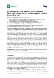
E. OBEX (Object Exchange): OBEX is a session protocol and can be resided on top of any reliable transport (e.g. IrTinyTP). It works for many devices that cannot afford the substantial resources required for an HTTP server. OBEX is enough like HTTP to serve as a compact final hop to a device. OBEX follows a client/server request-response (stop and wait) paradigm for the conversation format [1]. The terms client and server refer to the originator and receiver of the OBEX connection, not necessarily who originated the low level IrLAP connection. Requests are issued by the client (the party that initiates the OBEX connection). Once a request is issued, the client waits for a response from the server before issuing another request. The request/response pair is referred to as an operation. “PUT” and “GET” are the two types of operations used in OBEX. As the name indicates, the “PUT” operation sends one object from the client to the server, while the “GET” operation requests that the server return an object to the client. The maximum and minimum length for both request and response packets are 512K bits and 2048 bits respectively [1]. Fig.1 illustrates OBEX in the process of packetising a large object for transmission when OBEX is in the ‘PUT’ operation. The initial OBEX request packet (first packet) will typically, although not strictly required to do so, have certain headers. We assume that first packet includes the object information of name, length and body header. The connection-oriented session allows capabilities information to be exchanged just once at the start of the connection, and allows state information to be kept. The subsequent
5
ICC 2004
packets therefore only have to give the overhead information of the packet length field and the body header length field.
⋅⋅⋅
Object 1 byte
2 bytes
Response Response code length
OBEX Packets
REQ1
RES1
REQ2
RES2
REQ3
RES3
⋅⋅⋅
REQN
RESN
OBEX Turnaround 1 byte 2 bytes 1 byte 2 bytes lN
1 byte 4 bytes 1 byte 2 bytes n bytes
Packet Name Name Length Object Body Body OpCode Name Length Header Length header Length Header Length
payload
1 byte 2 bytes 1 byte 2 bytes n bytes OpCode
Packet Body Body payload Length Header Length
Figure 1: OBEX paketisation, where REQ stands for the request packet, while RES is the response packet.
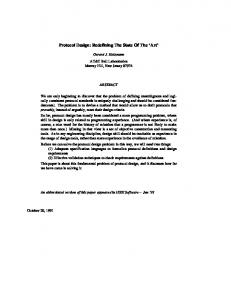
Fig.2 shows the protocol mapping of an OBEX request/response packet pair down to the link layer of the stacks (IrLAP). Symbols used in the modelling are listed in Table 1. Since OBEX uses ‘stop and wait’ as its transmission scheme, the transmitter has to wait for
the
acknowledgement
before
transmits
the
next
packet.
If
the
IrLAP
parameters l ⋅ N < Psend , one OBEX packet requires fragmentation in order to fit in IrLAP frames and requires more than one IrLAP window for its transmission. If l ⋅ N ≥ Psend , the OBEX packet can be accommodated within a single IrLAP window. The transmitter will simply set the ‘P’ bit at the end of each transmitted window and indicate an expected acknowledgement request from the other side. Thus, here we only need to consider the case of l ⋅ N ≤ Psend . Sending one OBEX request packet therefore needs several full IrLAP
6
ICC 2004
windows and it is likely that there will also be a single incomplete IrLAP window at the end.
OBEX +
PREQ OBEX Paylaod: Pl
6 bytes lOBEX
REQ
RES
1 byte
TinyTP + 2 bytes IrLMP
TinyTP Overhead: lTTP IrLMP Overhead: lLMP
9 bytes
IrLAP
⋅⋅⋅
IrLAP w indow
ACK
IrLAP w indow
ACK
⋅⋅⋅
IrLAP w indow
Lrem ACK
IrLAP + Physical Layer Overhead: lLAP+lPhy Tfull +Trem
ACK
TTA
TTA TRES
Figure 2: Mapping OBEX, TinyTP, IrLMP to IrLAP frames. TABLE I: Symbol. C pb p N l lPhy lLAP lLMP LTTP lOBEX PREQ Psend tI ts tack tta tFout TTA
Parameter Description Link data rate Link bit error rate Frame error rate Number of frames in one IrLAP window I-frame message data length Physical layer overhead: BOF+EOF+CRC S-frame length/ I-frame overhead IrLMP overhead IrTinyTP overhead OBEX request packet overhead OBEX request packet size Total packet length for IrLAP to send: PREQ+ lLMP+ lTTP Transmission time of an Information (I)-frame Transmission time of a Supervision (S)-frame Time to transmit an acknowledgement packet IrLAP minimum turnaround time IrLAP F-timer time-out period OBEX turnaround time
Unit bit/s bit 48bit 24bit 16bit 8bit 48bit bit bit sec sec sec sec sec sec
7
ICC 2004
III. MATHEMATICAL MODEL For the purpose of deriving the mathematical model, we assume that packets are sent in the OBEX ‘PUT’ operation mode. We only consider the ‘connected’ OBEX packets (not the first packet). Therefore, OBEX packet overhead is fixed in length. The length of the packet header is illustrated in Fig.3. The mathematical model and derivation of OBEX throughput for a connection using the IrDA protocol stacks follows next.
OBEX Payload
EOF
4bytes 1byte CRC
IrLMP Overhead TinyTP Overhead OBEX Overhead
IrLAP Overhead
IrDA Frames
BOF
1byte 3bytes 2bytes 1byte 6bytes
Figure 3: IrDA IrLAP frame structure.
Our throughput model is based on [10], which gave a detailed study for IrLAP and derived the IrLAP throughput formula in the presence of BER. It uses the concept of window transmission time tw [11]. tw denotes the average time needed for a full window transmission. It is the average time taken from the beginning of the window’s first frame transmission to the beginning of the first frame of the next window. It incorporates time needed for data frame transmissions, acknowledgements, and timer timeouts. Referring to [10], tw is given by: tw = NtI + p(tFout + ts ) + tack Where t I = (l + lLAP + lPhy ) / C , ts = (lLAP + lPhy ) / C , p = 1 − (1 − pb )
(1) l + lLAP + lPhy
, tack = 2tta + ts and
tFout = tI + 2tta .
8
ICC 2004
The number of frames correctly transmitted in one full window transmission Ncorr is also given in [10]: N corr =
(1 − p )(1 − (1 − p ) N ) p
(2)
As described in section II, we consider fixed overheads of 2 bytes and 1 byte for IrLMP and TinyTP respectively for each OBEX packet. Therefore, IrLAP has to transmit a packet with length of Psend = PREQ + lLMP + lTTP for each OBEX packet, Fig.2. One OBEX packet will be transmitted in several full IrLAP windows and one incomplete IrLAP window. By combining (1) and (2), the average time for sending the full IrLAP windows of one OBEX request packet is given in (3), where floor means round down to the nearest integer. ⎛ P ⎞ T full = floor ⎜ send ⎟ ⋅ tw ⎝ l ⋅ N corr ⎠
(3)
The length of the incomplete IrLAP window is given by: Lrem = Psend mod(l ⋅ N corr )
(4)
The number of frames in the incomplete IrLAP window is: N in = ceil ( Lrem / l)
(5)
Where ceil means round up to the nearest integer. The probability of having error/errors in the incomplete IrLAP window is:
pin1 = 1 − (1 − p ) Nin
(6)
Due to the small value of p, pin1 can be approximated as:
9
ICC 2004
pin1 = 1 − (1 − p ) Nin ≈ 1 − (1 − N in p ) = N in
(7)
While error/errors occur in transmitting the incomplete IrLAP window with probability pin1, due to the randomness of error occurrence, it is sufficient to assume that on average the error occurs in the middle of the window, and a retransmission will occur to recover the error with window length of 0.5Nin. If further error/errors occur in the retransmission
with
probability
of
pin 2 = pin1 (1 − (1 − p )0.5 N in ) ≈ 0.5N in 2 p 2 ,
another
retransmission window is needed with window length of half the previous, i.e. 0.25Nin, and so on. When the retransmission window is less than 1, we consider the whole window has been successfully transmitted. By including all the retransmissions, the average time for transmitting the incomplete window Trem is derived in (8), where X is an integer with value of X = ceil (0.5N in ) which satisfies 1 2 X ⋅ N in ≤ 1 1 1 Trem = N in t I + p ( t Fout + ts ) + tack + pin1 ( N in t I + p ( t Fout + t s ) + tack ) + ⋅ ⋅⋅ + pinN ( N in t I + p ( t Fout + t s ) + tack ) 2 2X 1 1 ⎛ ⎛ ⎞⎞ ⎞⎞ i ( i +1) i ( i −1) X ⎛ X ⎛ 2 2 1 1 ⎛ ⎞ ⎛ ⎞ i i ⎟⎟ ⎜ ⎟ ⎜ ⎜ ⎟ N t + 1+ N p + ⎜ N p N p ( ) ( ) = 1+ ( p ( t Fout + ts ) + tack ) in in in ⎜ ⎜⎜ ⎟ ⎟⎟ ⎟⎟ in I ⎜⎜ ⎜⎜ ⎟ ⎟⎟ ⎟⎟ i =1 ⎜ ⎝ 2 ⎠ i=2 ⎜ ⎝ 2 ⎠ ⎜ ⎝ ⎠⎠ ⎝ ⎠⎠ ⎝ ⎝
∑
∑
(8) Since the OBEX response packets are used only for acknowledgement (no payload), the packet length is equal to the OBEX overhead lOBEX. Due to the small size of the OBEX response packet, it can be accommodated in a single IrLAP window and we assume it is error free. The time required to transmit a response packet TRES is:
TRES =
(lOBEX + lLMP + lTTP ) + tack C
(9)
10
ICC 2004
By adding up all the time portions, as shown in Fig.2, the average time for transmission of one OBEX packet is:
T = T full + Trem + TRES + 2TTA
(10)
The OBEX throughput, which is defined as the useful data bit per second, is therefore given by: D=
PREQ − lOBEX T
(11)
In order to normalize the OBEX throughput, throughput efficiency is given by: TPE = D / C
(12)
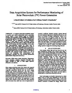
Using this mathematical model, in Fig.4, we compare the system throughput efficiency (TPE) for different data rates by using different OBEX packet sizes and turnaround time. OBEX TPE is plotted against BER. An average implemented IrLAP frame size l of 2048bit, window size N of 20 and minimum turnaround time tta of 10-5 s are used in the simulation. Unless otherwise specified, the same IrLAP parameters are used throughout this paper. As shown in Fig.4, the throughput efficiency decreases as the BER increases, and the system has larger TPE for low data rates. The results also show that different OBEX packet sizes and turnaround times have different effects on the TPE. PREQ and TTA have significant effects on the high data rate links, i.e. nearly 30% TPE difference between P1 and P2 is shown between Curve5 and Curve6 at BER=10-6. Therefore appropriately
11
ICC 2004
adjusting the OBEX parameters may improve the system performance significantly for high data rates.
Throughput Efficiency
1 0.9 0.8 0.7 0.6 0.5 0.4
Curve1 Curve3 Curve5
0.3 0.2 1.0E-06
Curve2 Curve4 Curve6
1.0E-05
1.0E-04
Bit Error Rate
Figure 4: OBEX TPE using different PREQ and TTA Curve1: P1, C=1Mb/s; Curve2: P2, C=1Mb/s; Curve3: P1, C=10Mb/s; Curve4: P2, C=10Mb/s; Curve5: P1, C=100Mb/s; Curve6: P2, C=100Mb/s. where P1: PREQ=50Kbit, TTA=10-4s; P2: PREQ=500Kbit, TTA=10-3s.
IV. OBEX PARAMETERS OPTIMISATION As shown in the previous section, OBEX packet size and turnaround time have significant effects on the system TPE. However, OBEX performance can be optimized by choosing appropriate OBEX parameters for any data rates and BERs. In this section, we are going to carry out a detailed study for the OBEX packet size and turnaround time by mathematical analysis and simulation results. First, the OBEX packet size PREQ is a negotiable parameter for the connection. Because its value can be chosen from 2Kbits to 512Kbits [1], it is very important to understand the effect of PREQ on the throughput.
12
ICC 2004
Considering the large size of PREQ, it is sufficient to assume that PREQ is much larger than the incomplete IrLAP window Lrem. By combining equations (3) and (8), the time to transmit PREQ becomes: ( PREQ + lLMP + lTTP ) ⋅ tw
T full + Trem ≈
l ⋅ N corr
(13)
PREQ is also large by comparing to the overheads of IrLMP, IrTinyTP and OBEX, thus, we assume PREQ − lOBEX ≈ PREQ and PREQ + lLMP + lTTP ≈ PREQ . Applying these assumptions to the OBEX throughput equation (11), it becomes:
D≈
PREQ
PREQ ⋅ p ⋅ tw + TRES + 2TTA l ⋅ (1 − p) ⋅ (1 − (1 − p) N )
(14)
By using the approximation of equation (7) and setting A = (TRES + 2TTA ) ⋅ l ⋅ (1 − p ) ⋅ N ⋅ p , we can further simplify equation (14) as: D=
PREQ ⋅ N ⋅ p ⋅ l ⋅ (1 − p ) PREQ ⋅ p ⋅ tw + A
(15)
In equation (15), factor A is independent of PREQ. By considering N ⋅ p >> p and l ⋅ (1 − p ) >> tw , we then have l ⋅ (1 − p ) ⋅ N ⋅ p >> p ⋅ tw . Therefore, we can conclude that the
throughput D increases with PREQ, which means the system always acquires its maximum throughput at a maximum value of PREQ. According to the standard [1], the upper limit of 512kbit should therefore be used for optimum PREQ. Second, the OBEX turnaround time TTA in (14), is only presented in the denominator. It leads to the conclusion that throughput D increases when TTA decreases.
13
ICC 2004
As shown in the analysis, larger PREQ should offer better OBEX throughput. For TTA, we have proved that the system throughput will always benefit from smaller TTA. It is interesting to see if the throughput can be improved significantly if we were to use even larger PREQ values and smaller TTA. Using (11) and (12), in Fig.5, the OBEX TPE as a function of OBEX packet size PREQ in the range of 5 × 10⁴ ~ 1 × 106 bit is examined at BER of 10-6 with TTA of 10-4s at three different data rates of 1Mbps, 10Mbps and 100Mbps. In the same figure, the OBEX TPE is also plotted against TTA in the range of 1 × 10⁻⁵ ~ 1 × 10⁻² s at 1Mbps, 10Mbps and 100Mbps. PREQ is set at 500Kbit. OBEX turnaround time T TA (s) 1.00E-05
1.00E-04
1.00E-03
1.00E-02
1.00E-01
0.95
1
0.85 0.6 0.4 0.75
TPE ( TTA )
TPE ( PREQ )
0.8
0.2 0.65 5.0E+04
0 5.0E+05
9.5E+05
OBEX size P REQ (bits) PREQ, data rate=1Mbps PREQ, data rate=100Mbps TTA, data rate=10Mbps
PREQ, data rate=10Mbps TTA, data rate=1Mbps TTA, data rate=100Mbps
Figure 5: OBEX TPE against PREQ with TTA=10-4s, and OBEX TPE against TTA with PREQ=500Kbit. BER=10-6.
For PREQ, the corresponding OBEX TPE curves show non-linear shapes in Fig.5. This is due to the change of the incomplete IrLAP window LREM that we ignored in (13).
14
ICC 2004
However, in spite of the slight fluctuation, TPE increases with PREQ at all data rates. This verifies our analysis for the optimum PREQ. The TPE at 100Mbps benefits most as PREQ increases, while at lower speeds, the benefits are small for very large PREQ. For TTA, all of the three OBEX TPE curves decrease with increasing TTA. Links at high data rates are more sensitive and vulnerable to the large TTA than at the low data rates. Larger PREQ will improve the throughput, however, larger memory buffer size has to be assigned for temporarily storing the unfinished (current transmitting) packet. Given the fact that buffer size is constrained for the resource-limited wireless device, PREQ should not be over size. For TTA, this high layer turnaround time depends on the CPU speed of the communication peers rather than the IrDA transceivers themselves. Therefore, smaller TTA requires faster CPU. Smaller TTA can improve the throughput but very small TTA only leads to trivial improvement on the throughput, Fig.5. In order to give a suitable parameters selection guideline, we are going to search the suitable PREQ and TTA values for various data rates based on the ‘best throughput efficiency’. By considering 2% sacrifice off the best TPE, we can compromise the throughput and the hardware requirement. For PREQ, the best TPE (PBTPE) is obtained by using very large PREQ equal to 4Mbit with TTA=10-4s. OBEX TPE is calculated by increasing PREQ until TPE = 0.98 × PBTPE for each data rate. The corresponding PREQ values are recorded as the recommended values. Using the same process, the best TPE (TBTPE) for TTA is calculated by using very small TTA of 10-6s with PREQ=500Kbit. The recommended TTA for
15
ICC 2004
each data rate is obtained by recording the corresponding TTA value for TPE = 0.98 × TBTPE . By using the suggested PREQ and TTA values, very good throughput (98% of the best TPE) can be obtained for the system with less hardware requirements. In Fig.6, the recommended PREQ and TTA values are plotted against data rate at BER=10-6. Note that TTA is shown in logarithmic scale. 1.0E-01
8.0E+05
1.0E-02 Turnaround time
6.0E+05
1.0E-03 4.0E+05 1.0E-04
Packet size
2.0E+05 0.0E+00 1.0E+05
1.0E+06
1.0E+07
OBEX Turnaround Time
OBEX Packet Size
1.0E+06
1.0E-05 1.0E+08
Data Rate (bit/s) OBEX packet size
OBEX turnaround time
Figure 6: PREQ and TTA selection guidelines
As shown in Fig.6, PREQ increases its size exponentially after the data rate reaches 1Mbps, while TTA decreases linearly with the data rate. For the 100Mbps links, PREQ of 0.8Mbit and TTA of 0.05ms are sufficient to obtain very good TPE for the system. Fig.7 shows the OBEX TPE by using the recommended optimum PREQ and TTA values. Results are plotted against BER in three different data rates of 1Mbps, 10Mbps and 100Mbps.
16
ICC 2004
Comparing Fig.7 to the non-optimum cases in Fig.4, considerable improvement on OBEX TPE is shown for the same BER. The system is benefited significantly by using the optimum PREQ and TTA values especially for high data rates.
Throughput Efficiency
1 0.9 0.8 0.7 0.6 0.5
data rate=1Mbps data rate=10Mbps data rate=100Mbps
0.4 0.3 0.2 1.0E-06
1.0E-05
1.0E-04
Bit Error Rate
Figure 7: OBEX TPE using the recommended PREQ and TTA values
V. CONCLUSION This article examined the performance of OBEX protocol running on top of the IrDA protocol stack. We carried out an analytical model to derive the OBEX throughput equation which depends on BER. Based on the mathematical model, we examined the impact of OBEX packet size and turnaround time on OBEX TPE. In order to maximise throughout, optimum OBEX packet size and turnaround time have been studied. The analysis has showed that the throughput always benefits by a large OBEX packet size and a small turnaround time. A suitable OBEX parameter selection guideline is given for
17
ICC 2004
different data rates. The system performance shows significant improvement by applying the optimized values.
REFERENCES [1] IrDA, Object Exchange Protocol (IrOBEX), Version 1.3, March, 2003 [2] Sairam, K.V.S.S.S.S.; Gunasekaran, N.; Redd, S.R.; ‘Bluetooth in wireless communication’, IEEE Communications Magazine, Volume: 40 Issue: 6, Jun 2002 Page(s): 90 -96 [3] Srivastava, A.; Friday, R.J.; Ritter, M.W.; Filippo, W.S.; ‘A study of TCP performance over wireless data networks’ VTC 2001 Spring. IEEE VTS 53rd, Volume: 3, 2001 Page(s): 2265 2269 vol.3 [4] IrDA, Serial Infrared Physical Layer Specification, Version 1.1, 1995 [5] IrDA, Serial Infrared Physical Layer Specification for 16Mb/s Addition (VFIR)–Errata to version 1.3, 1999 [6] IrDA, Serial Infrared Link Access Protocol (IrLAP), Version 1.1 1996 [7] IrDA, Link Management Protocol (IrLMP), Version 1.1, 1996 [8] IrDA, Tiny Transport Protocol (IrTinyTP), Version 1.1, 1996 [9]
A.
C.
Boucouvalas,
V.Vitsas
'Optimum
Window
and
Frame
Size
for
IrDA
Links'.I.E.E.Electronic Letters, Vol.37, No.3, pp194-196, 2001. [10] P. Barker, A.C. Boucouvalas, “Performance modelling of the IrDA protocol for Infrared Wireless Communications” IEEE Communications magazine, Vol.36, No.12, pp.113-117, December 1998. [11] Bux W., Kummerle K. & Truong H.L., “Balanced HDLC procedures: A performance Analysis”, IEEE Trans.Com, 1980, com-28, pp.1889-1898.
18