VOLUME 82, NUMBER 2
PHYSICAL REVIEW LETTERS
11 JANUARY 1999
Generalized Field Propagator for Arbitrary Finite-Size Photonic Band Gap Structures Olivier J. F. Martin* Electromagnetic Fields and Microwave Electronics Laboratory, Swiss Federal Institute of Technology, ETH-Zentrum, 8092 Zurich, Switzerland
Christian Girard Centre d’Elaboration de Matériaux et Etudes Structurales, CEMES/CNRS, B.P. 4347, 31055 Toulouse Cedex 4, France
David R. Smith and Sheldon Schultz Department of Physics, University of California, San Diego, 9500 Gilman Drive, La Jolla, California 92093-0319 (Received 23 June 1998) We investigate the properties of photonic band gap structures of finite size and arbitrary geometry using the density of states deduced from scattering calculations. We first demonstrate this procedure on a finite 2D array of cylinders and then study at optical frequencies a system formed by a finite array of finite height cylinders positioned on a substrate and illuminated with an evanescent field. [S0031-9007(98)08191-5] PACS numbers: 42.70.Qs, 42.25.Fx, 42.68.Mj
The electromagnetic (EM) properties of infinitely periodic dielectric and metallic systems have been studied extensively in the context of photonic band gap (PBG) structures [1,2], where powerful numerical methods exist that take advantage of the periodicity. Any physical realization of a PBG structure, however, is finite, and thus will have electromagnetic properties and phenomena distinct from an infinite structure. Such phenomena may include surface modes, sensitivity to boundary termination, or band-edge resonances [3–5]. The objective of this Letter is twofold. First, we present a new method of computing the EM properties of a finite PBG structure. Second, we use this approach to study an array of finite-height dielectric cylinders on a substrate, illuminated with an evanescent field. This geometry was chosen to demonstrate the versatility of the scattering method, since it is a nontrivial three-dimensional finite system with open boundary conditions. Furthermore, this configuration is accessible experimentally, requiring only a single PBG layer which could readily be fabricated by lithographic methods. Accurate numerical methods previously reported for calculating the properties of finite PBG structures include modal method [6], finite difference time domain [7], transfer matrix [8,9], and repeated supercell [10]. Our method uses a scattering solution to obtain the EM modes and modes density associated with an arbitrary finite PBG region. The scattering solution is based on the Green’s tensor technique in the frequency domain. Let us consider a scattering system ´sr; vd embedded in an infinite homogeneous background ´B svd like the finite sn 3 md lattice of infinite cylinders shown in Fig. 1(a). We assume harmonic fields with the usual expf2ivtg dependence. When the system is illuminated by an incident field E0 sr; vd, the total electric field 0031-9007y99y82(2)y315(4)$15.00
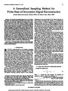
Esr; vd is a solution of the Fredholm equation of the second kind, Esr; vd E0 sr; vd Z v2 1 dr 0 G0 sr, r 0 ; vd ? 2 D´sr 0 ; vdEsr 0 ; vd , c (1) where c is the speed of light; D´ is the dielectric contrast: D´sr; vd ´sr; vd 2 ´B svd; and the integration runs over the entire scatterer volume. The kernel G0 of Eq. (1) is the Green’s tensor associated with an infinite homogeneous background ´B . The value of this dyadic for 2D and 3D systems is given in Ref. [11]. Since G0 (a)
y ϕi x
(b)
z
0
Ep
0
θi
Es
FIG. 1. Geometry of the system under study. (a) Cross section of a finite size s4 3 3) 2D array of infinite dielectric cylinders on a triangular lattice; ( b) surface structure composed by the same array but with finite-height cylinders deposited on a transparent substrate and illuminated from underneath by total internal reflection.
© 1999 The American Physical Society
315
VOLUME 82, NUMBER 2
PHYSICAL REVIEW LETTERS
diverges for r r 0 the principal value must be taken in Eq. (1) as described in Ref. [11]. For simplicity, let us rewrite Eq. (1) in operator notation, E E0 1 G0 ? D´E .
(2)
We recently showed that an alternative form of Eq. (2) existed [12], E E0 1 G ? D´E0 ,
(3)
where the Green’s tensor G fulfills Dyson’s equation, G G0 1 G0 ? D´G ,
(4)
and forms the basis of the generalized field propagator formalism introduced in Ref. [12]. The tensor G contains the entire response of the system under study and provides a powerful way of computing the scattered field for arbitrary excitations. To investigate finite-size PBG structures, one can use the previous formalism to compute the field transmitted or reflected by the structure as a function of the frequency and identify allowed or forbidden frequency regions from these data. Alternatively, however, we can compute the density of states (DOS) directly from the Green’s tensor G, which also functions as an important indicator of band gap regions in PBG structures. In analogy with quantum mechanics [13], the DOS is obtained from the imaginary part of the trace of the Green’s tensor G, DOS , ImhvTrsGdj .
(5)
It is important to note that the numerical DOS obtained this way is related to the space spanned by the discretized geometry used for the calculation of G. Note that one can also define a local density of states DOSsrd , ImhvGsr, rdj which accounts for the variation of spontaneous emission at a particular location [14]. To demonstrate the correlation of the DOS with the band gap regions of a finite PBG structure, we consider a finite s6 3 6d array of cylinders with radius r, placed on
11 JANUARY 1999
a triangular lattice of period a [Fig. 1(a)]. We assume that the cylinders are infinitely long and the field propagates in the plane of Fig. 1(a). Two different polarization modes exist in such a 2D system: Transverse magnetic (TM), where the electric field is parallel to the cylinders axis, and transverse electric (TE), where it is in the plane of Fig. 1(a). The TM photonic band structure, computed using the plane wave method [15], for an infinitely periodic lattice is given in the left part of Fig. 2. Four different forbidden regions can be observed. In the right part of Fig. 2 we present the DOS computed with Eq. (5) for a s6 3 6d finite array. The four different forbidden regions are also clearly evident from these data. Typically, peaks occur in the DOS at the band edge, as has also been observed for an infinite triangular lattice [16]. Let us emphasize that the DOS shown in Fig. 2 is computed for a geometry with extremely limited extent; all together, there are only 33 cylinders in the system. To observe band gaps for TE modes, we reduce the filling factor to rya 0.2 [17], leading to a PBG around v 2pcya. In Fig. 3 we compare the TE band structure for an infinite lattice with the DOS computed for a finite s6 3 6d array. Again, there is excellent agreement between the two. It seems appropriate here to say a few words on the practical calculation of DOS for TM and TE polarizations using Eq. (5). For TM polarization, the electric field has only one component, E Ez ez (Fig. 1). Green’s tensors G0 and G reduce then to scalar functions. On the other hand, for TE polarization, the electric field has two components: E Ex ex 1 Ey ey so that G0 and G become s2 3 2d matrices [11]. For each polarization, G can be computed from G0 using an iterative series of Dyson’s equations [12] and then DOS obtained by summing the diagonal elements of G. We now present a finite-size PBG structure similar to that investigated in Fig. 3, but which is amenable to fabrication for use at optical wavelengths.
FIG. 2. 2D PBG structure of infinitely long dielectric cylinders s´ 9d in air s´B 1d on a triangular lattice with a filling factor rya 0.35 and for TM polarization; the corresponding irreducible Brillouin zone is shown in the inset. Left: Band structure computed for an infinite lattice using plane wave expansion; right: DOS for a finite s6 3 6d lattice computed with Eq. (5). Note the clear correlation between the band gaps (left) and the minima in DOS (right).
316
VOLUME 82, NUMBER 2
PHYSICAL REVIEW LETTERS
11 JANUARY 1999
2.5
ω (πc/a)
2.0 1.5 1.0 0.5 Γ
FIG. 3.
K
M
Γ
250
500 DOS (arb. units)
750
1000
Same situation as in Fig. 2, but for TE polarization and a filling factor rya 0.2.
Consider a dielectric substrate patterned with an s6 3 6d array of finite-height cylinders [Fig. 1(b)], illuminated from underneath at a large angle of incidence ui , so that the field is totally internally reflected (TIR). This illumination mode generates an evanescent field above the substrate that propagates in the direction parallel to the surface. From the two s and p illumination polarizations that can be distinguished in this system [Fig. 1(b)], we will only consider here s polarization since it corresponds to the TE polarization of a 2D system. Indeed, for s polarization the incident field is parallel (and therefore continuous) to all horizontal interfaces, including at the ends of the finiteheight cylinders. Therefore, such a 3D system exhibits behavior similar to a 2D system under TE polarization. For given permittivities ´ and ´B , the location of the PBG depends only on the filling factor rya. It is therefore possible, within experimentally realistic limits, to scale the geometry so that a PBG arises in a particular frequency region. We take cylinders with radius r 120 nm and height h 80 nm on a triangular lattice of period a 600 nm. Such dimensions are within the capability of electron beam lithography or even UV contact lithography [18]. The permittivity of the cylinders is ´ 9, so that this system is similar to the structure described in Fig. 3, with the frequency v 2pcya corresponding to a wavelength l 600 nm. For the substrate we take ´sub 2 which gives a TIR critical angle ui 45±. To ensure that only an evanescent field is established above the substrate, we calculate for a larger angle and take ui 70±. The incident field is propagating at an angle wi 35± through the lattice [Fig. 1(a)]. In Fig. 4 we present the field intensity above this finitesize array of cylinders as a function of the illumination wavelength l (for convenience a frequency scale similar to that of Fig. 3 is also shown). The corresponding surface Green’s tensor G0 is given in Ref. [19]. The extremely sharp peak at l 693 nm corresponds to the DOS peak at the lower band edge in Fig. 3. The band gap region between l ø 600 700 nm fv ø s2 1.7d spcyadg is clearly demonstrated in Fig. 4. The behavior of the
transmitted field above the substrate is quite complex and will be presented in detail elsewhere. The intensity sharp peak at l 693 nm corresponds to extremely strong scattering by the structure, as illustrated in Fig. 5(a), where we present the field intensity distribution above the system. Note that the field is scattered in a specific geometrical pattern in the region outside of the actual array. The maximum intensity in this figure is 9.0 times the intensity of the illuminating field below the surface, which is particularly striking when one recalls that for TIR illumination only an evanescent field is established above the surface. The intensity measured in Fig. 5(a) therefore corresponds to an enhancement of 2.7 3 104 compared to the field intensity that would be observed above a bare surface. A completely different field distribution is observed at another wavelength, e.g., l 600 nm [Fig. 5(b)]. There the field remains strongly localized in the region of the cylinder array and now reaches an intensity 1.3 times that ω (πc/a) 2.4 2.0
2
1.7
1.5
700
800
1.5 I (arb. units)
0.0
1.0 0.5 0.0 500
600 λ (nm)
FIG. 4. Field intensity above a s6 3 6d finite-size surface structure [Fig. 1( b)], as a function of the illuminating wavelength. Same lattice parameters as in Fig.3. The total field intensity I is computed at a constant height z 500 nm above the substrate. The intensity of the illuminating field below the surface (TIR) is equal to 1.
317
VOLUME 82, NUMBER 2
PHYSICAL REVIEW LETTERS
11 JANUARY 1999
interaction with the greatly altered DOS [23]. The strong enhancement of the field above the surface as well as the marked frequency selectivity may be of use in imaging or integrated optic devices. Finally, this enhanced field could also be used for making evanescent-wave atom mirrors [24]. In addition, the direct calculation of DOS based on the generalized field propagator technique as presented in this Letter should be useful for the investigation of finitesize PBG structures with arbitrary shaped scatterers or for random scattering systems. This work was supported by the Swiss National Science Foundation and by the U.S. NSF (No. NSF-DMR-9623949).
FIG. 5. Topology of the field intensity above a s6 3 6d finitesize surface structure [Fig. 1( b)]. The intensity is computed at a constant height z 500 nm above the substrate for two different illuminating wavelengths: (a) l 693 nm and ( b) l 600 nm.
incident, which again has to be compared to the evanescent value of the order of 1024 . This strong scattered field remains bound to the surface and rapidly decreases when one moves away from the interface. Contrary to the extraordinary optical transmission measured recently by Ebbesen et al. on subwavelength hole arrays in metallic films [20] or to former reflection experiments by Kitson et al. [21], the strong scattering enhancement evidenced in our system does not involve any plasmon resonances, and incorporates only a very limited number of scatterers. We believe that finite surface PBG structures under TIR illumination are attractive from several points of view: They constitute open 2D systems, where the topology of the transmitted field can be measured, e.g., by means of optical near-field microscopy [22]. Since the system is open, active components, such as fluorescent molecules, can be placed within the lattice to investigate radiative
318
*E–mail address:
[email protected] [1] C. M. Bowden, J. P. Dowling, and H. O. Everitt, J. Opt. Soc. Am. B 10, 280 (1993). [2] Photonic Band Gaps and Localization, edited by C. M. Soukoulis (Plenum, New York, 1993). [3] R. D.Meade et al., Phys. Rev. B 44, 10 961 (1991). [4] W. M. Robertson et al., Opt. Lett. 18, 528 (1993). [5] J. M. Bendickson, J. P. Dowling, and M. Scalora, Phys. Rev. E 53, 4107 (1996). [6] G. Tayeb and D. Maystre, J. Opt. Soc. Am. A 14, 3323 (1997). [7] P. R. Villeneuve, S. Fan, and J. D. Joannopoulos, Phys. Rev. B 54, 7837 (1996). [8] M. Sigalas et al., Phys. Rev. B 48, 14 121 (1993). [9] J. B. Pendry, J. Mod. Opt. 41, 209 (1994). [10] R. D. Meade et al., Phys. Rev. B 48, 8434 (1993). [11] O. J. F. Martin and N. B. Piller, Phys. Rev. E 58, 3909 (1998). [12] O. J. F. Martin, C. Girard, and A. Dereux, Phys. Rev. Lett. 74, 526 (1995). [13] E. N. Economou, Green’s Functions in Quantum Physics (Springer-Verlag, Berlin, 1990), 2nd ed. [14] F. Wijnands et al., Opt. Quantum Electron. 29, 199 (1997). [15] D. R. Smith et al., J. Opt. Soc. Am. B 10, 314 (1993). [16] M. Plihal and A. A. Maradudin, Phys. Rev. B 44, 8565 (1991). [17] J. N. Winn, R. D. Meade, and J. D. Joannopoulos, J. Mod. Opt. 41, 257 (1994). [18] H. Schmid et al., Appl. Phys. Lett. 72, 2379 (1998). [19] C. Girard et al., Phys. Rev. B 52, 2889 (1995). [20] T. W. Ebbesen et al., Nature (London) 391, 667 (1998). [21] S. C. Kitson et al., Phys. Rev. Lett. 77, 2670 (1996). [22] Photons and Local Probes, edited by O. Marti and R. Möller (Kluwer, Dordrecht, The Netherlands, 1995). [23] E. Yablonovitch, Phys. Rev. Lett. 58, 2059 (1987). [24] J. P. Dowling and J. Gea-Banacloche, Adv. At. Mol. Opt. Phys. 37, 1 (1996).