198
IEEE TRANSACTIONS ON CIRCUITS AND SYSTEMS—I: FUNDAMENTAL THEORY AND APPLICATIONS, VOL. 50, NO. 2, FEBRUARY 2003
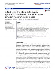
Generating Chaotic Attractors With Multiple Merged Basins of Attraction: A Switching Piecewise-Linear Control Approach Jinhu Lü, Xinghuo Yu, Senior Member, IEEE, and Guanrong Chen, Fellow, IEEE
Abstract—This paper presents several new chaos generators, switching piecewise-linear controllers, which can generate some new chaotic attractors with two or three merged basins of attraction from a given three-dimensional linear autonomous system within a wide range of parameter values. Based on this success, chaotic attractors with merged basins of attraction are further generated using a formalized controller design methodology. Basic dynamical behaviors of the controlled chaotic system are then investigated via both theoretical analysis and numerical simulation. To that end, the underlying chaos-generation mechanism is further explored by analyzing the parameterization of the controlled system and the dynamics of the system orbits. Index Terms—Basin of attraction, chaos generation, piecewiselinear controller, switching system.
I. INTRODUCTION
I
N THE last few years, experience has shown that chaos can actually be useful and can also be well controlled [1]–[3]. As a result, the study of chaotic dynamics has seen an expansion from the traditional concern of understanding and analyzing chaos to the new attempt of controlling and utilizing it. Recently, exploiting chaotic dynamics in high-tech and industrial engineering applications has attracted more and more interest, in which much attention has focused on effectively creating chaos [3]–[5], particularly using simple devices such as nonlinear circuits [6]–[8] and switching piecewise-linear controllers [9]–[15]. It is well known that piecewise functions can easily create various chaotic attractors [8]–[18]. Typical examples include the -scroll circuits [16], [17]. Motivated by many examples of this type , Lü et al. [10] introduced a switching piecewiselinear controller [10], which can create chaos from a given linear autonomous system within a wide range of parameter values; Zheng et al. [11] further modified the controller to generate two chaotic attractors simultaneously. These case studies have shown that simple analog chaos generators indeed have strong capability of generating chaos. Manuscript received December 4, 2002; revised September 7, 2002. This work was supported in part by the Hong Kong Research Grants Council CERG under Grant 1018/01E and in part by the K. C. Wong Education Foundation, Hong Kong, 2002. J. Lü is with the Institute of Systems Sciences, Academy of Mathematics and System Sciences, Chinese Academy of Sciences, Beijing 100080, China (e-mail:
[email protected]). X. Yu is with the School of Electrical and Computer Engineering, Royal Melbourne Institute of Technology University, Melbourne, Australia (e-mail:
[email protected]). G. Chen is with the Department of Electronic Engineering, City University of Hong Kong, Kowloon, Hong Kong (e-mail:
[email protected]). Digital Object Identifier 10.1109/TCSI.2002.808241
This paper furthers the studies of [10], [11], to investigate the generation of chaotic attractors with multiple merged basins of attraction in a simple control system. The key is to redesign the controller that can generate a chaotic attractor with a single basin of attraction. Two new switching schemes will be introduced into the piecewise-linear controller previously studied in [10] and [11], thereby endorsing the redesigned controller an ability of generating chaotic attractors with two or three merged basins of attraction, from a given simple linear autonomous system. Furthermore, a formalized design procedure is suggested for generating chaotic attractors with merged basins of attraction. Finally, basic dynamical behaviors of the controlled chaotic system are investigated in some detail, by employing some mathematical tools developed in [19]. In particular, the underlying chaos generation mechanism in switching systems is explored, by analyzing the parameterization of the controlled system and the dynamics of the system orbits. II. SWITCHING CONTROLLED CHAOTIC SYSTEM Consider the following simple linear controlled system: (1) where
and
with a switching piecewise-linear controller if
(2)
otherwise where are real parameters. This controlled system (1)–(2) can generate chaos within a wide range of parameter values [9]. Zheng et al. [11] has further improved the controller (2) to be the following one:
1057-7122/03$17.00 © 2003 IEEE
if
and
if
and
otherwise
(3)
LÜ et al.: GENERATING CHAOTIC ATTRACTORS WITH MULTIPLE MERGED BASINS OF ATTRACTION
199
Fig. 1. Upper and lower chaotic attractors generated by the switching controller (3).
Fig. 2.
Three chaotic attractors created by the switching controller (4).
where are real parameters. Under this controller, the controlled system (1)–(3) can simultaneously generate two chaotic attractors, an upper attractor and a lower at, , , tractor, as shown in Fig. 1, when , , , and [11]. The maximum Lya. punov exponents of the two attractors are both is the invariant manifold of (1)–(3). It is noticed that A closer look at the controller (3) reveals that it has two ( ) deswitchings: one is on the surface noted by , and the other is on the surface ( ) denoted by . Taking parameters and , and are it is found that the above two switching planes . Furthermore, symmetrical about the invariant manifold of the upper attractor, belongs for any point to the lower attractor, that is, the upper attractor and the lower shown attractor are symmetrical with respect to the plane in Fig. 1. In fact, the lower attractor can be attained by turning by 180 deg. the upper attractor around the plane Similarly, one can easily create attractors simultaneously in the switching system (1) by two transforms, parallel displacement and rotation. In fact, since the chaotic attractor is bounded by a finite sphere, one can partition the whole space into disjoint subspaces, and then duplicate the original attractor, the upper attractor or the lower attractor into every subspace. For example, if one partitions the whole space into two subspaces
and , and then duplicates , and finally the upper attractor into subspace overturns the upper attractor, then, two attractors are obtained simultaneously as shown in Fig. 1. Now, to further generate three chaotic attractors simultaneously in (1), the controller (2) is restructured as follows: if if otherwise if if, otherwise if, if otherwise (4)
200
IEEE TRANSACTIONS ON CIRCUITS AND SYSTEMS—I: FUNDAMENTAL THEORY AND APPLICATIONS, VOL. 50, NO. 2, FEBRUARY 2003
Fig. 3.
Four chaotic attractors (upper and lower) generated by the switching controller (5).
where are real parameters. The controlled system (1)–(4) can simultaneously generate three chaotic attrac, , , , tors as shown in Fig. 2, when , , and . It is noticed that , , and are all invariant manifolds of system (1)–(4). To simultaneously create four chaotic attractors (upper and lower) in system (1), the controller (3) is furthermore restructured as follows:
if if
if
Fig. 4. Subspaces of (1).
and
ural symmetry under the coordinates transform , one can partition the whole space along the axis , respectively, as into subspaces, with heights shown in Fig. 4. Then, one can duplicate the original attractor into every subspaces, thereby generating attractors simultaneously in (1). It is noticed that one only needs to segment and ( ) were used displace the axis. In fact, above to substitute for in the controller (2) or (3), and it is very easy to modify the controller this way. However, it must be noted that the above attractors are independent of one another. That is, there is no system orbit that connects all attractors together. What is more interesting is actually a single and yet complex chaotic attractor that has multiple merged basins of attraction. This is the topic of study in the next section.
and
otherwise if if
and
if
and ,
otherwise (5) are real parameters. The conwhere trolled system (1)–(5) can simultaneously generate four chaotic , attractors (upper and lower) as shown in Fig. 3, when , , , , , and . The above procedure can be carried on and on, so as to generate attractors using only parallel displacement and rotation transformations. Since the controlled system (1) has a nat-
III. GENERATING CHAOTIC ATTRACTORS WITH MULTIPLE MERGED BASINS OF ATTRACTION In this section, the above-designed controllers are further restructured for generating chaotic attractors with multiple merged basins of attraction in the controlled system (1). A closer look at the controller (3) reveals that it has two and separately, which are switchings on the surfaces responsible for the creation of the two chaotic attractors. The is responsible for creating the switching on the surface upper-chaotic attractor; while the switching on the surface
LÜ et al.: GENERATING CHAOTIC ATTRACTORS WITH MULTIPLE MERGED BASINS OF ATTRACTION
(a)
201
(b)
Fig. 5. Chaotic attractor with two merged basins of attraction, generated by the switching controller (6).
creates the lower-chaotic attractor. It is noticed that the plane is the invariant manifold of (1), which partitions the whole space into two invariant subspaces, and . It means that the orbit of the upper , and attractor will remain in the subspace . Similarly, not enter into the subspace the orbit of the lower attractor will not enter the subspace . To connect together the orbits of the upper and lower attractors, one must use control to force the orbit of the upper-atand then enter into the tractor to go through the plane . At the same time, the control subspace should force the orbit of the lower attractor to go through the and then return to the subspace . plane is used to subBased on this observation, stitute for 0 in the controller (3), therefore yielding the following new controller:
if
and
if
and
otherwise (6) are all real parameters. where is the control gain, and is In the controller (6), , that is, when the orbit is in the control direction. When , the negative control is the subspace added to force the orbit to enter into the subspace ; when , that is, when the orbit is in the subspace
, the positive control is added to force . Thus, the orbit to enter into the subspace one can actually connect the orbits of the upper and lower attractors together, thereby forming a single and complex chaotic , , attractor. The result is shown in Fig. 5(a), where , , , and . Fig. 5(b) is the – plane projection of the attractor. It is clear from Fig. 5 that the chaotic attractor has two merged basins of attraction, the upper basin of attraction and the lower basin of attraction. If the orbit starts from inside of the sub, then, it will run inside the upper space basin of attraction for some time, then move into the subspace and run inside the lower basin of attraction for some time, and finally return to the subspace and then restart a new cycle. A closer look at the controller (6) reveals that it has three , in which the two switching switching planes: , , and and are responsible for the generation of two planes chaotic attractors, the upper chaotic attractor and the lower is responsible chaotic attractor; while the switching plane for the connection of these two chaotic attractors. Similarly, one can generate a chaotic attractor with three merged basins of attraction. In doing so, the controller (6) is furthermore modified. One first partitions the whole space into and . In two subspaces , the controlled system (1) has subspace a chaotic attractor with two merged basins of attraction, as , (1) has seen in Fig. 5, while in subspace an upper attractor, as seen in Fig. 1. To generate the intended chaotic attractor with three merged basins of attraction, one has to connect the upper attractor to the chaotic attractor with two merged basins of attraction. Control is used to force the orbit and then of the upper attractor to go through the plane . At the same time, enter into the subspace the control also forces the orbit of the chaotic attractor, the one that has two merged basins of attraction, to go through the and then return to the subspace . plane
202
IEEE TRANSACTIONS ON CIRCUITS AND SYSTEMS—I: FUNDAMENTAL THEORY AND APPLICATIONS, VOL. 50, NO. 2, FEBRUARY 2003
(a)
(b)
Fig. 6. Chaotic attractor with three merged basins of attraction, generated by the switching controller (7).
To do so, is employed to substitute for 0 in the controller (2), resulting in the following new controller:
if if
and
if
and
otherwise if if
otherwise (7) are all real parameters. where is the control gain, and and In controller (7), are the control directions. When , that is, , the negative when the orbit is in the subspace is added to force the orbit to enter into the control ; when , that is, when the subspace , the positive control orbit is in the subspace is added to force the orbit to enter into the subspace . This way, the orbits of the upper attractor and the chaotic attractor with two merged basins of attraction are
connected together, forming a single but more complex chaotic attractor. The result is shown in Fig. 6(a), where , , , , , , and . Fig. 6(b) is the – plane projection of the attractor. It is clear from Fig. 6 that the chaotic attractor has three merged basins of attraction: two upper basins of attraction and one lower basin of attraction. If the orbit starts from inside of , then it will run inside the first the subspace upper basin of attraction for some time, then go into the suband then run inside the second space upper basin of attraction for some time, and then go into the and run inside the lower basin subspace of attraction for some time, and then return to the subspace and run inside the second upper basin of attraction for some time, and finally return to the subspace and then restart a new cycle. It is clear that the controller (7) has five switching planes, , , , , . Among them, three switching and , , and planes, , are responsible for generating three chaotic attractors separately, and the other two switching planes, and , are responsible for connecting the above three chaotic attractors together so as to form a single and complex chaotic attractor. Similarly, chaotic attractors with merged basins of attraction can also be generated. The formalized design method is summarized as follows. subspaces along the 1) Partition the whole space into -axis, as shown in Fig. 4. 2) Duplicate the original attractors, the upper-attractor and the lower-attractor, to every subspaces. 3) Use the switching control strategy to connect all the independent attractors, so as to form a single complex chaotic attractor, as depicted by Fig. 7. Here, the switching control strategy can be chosen as , where the height (between two neighboring subspaces) should be smaller than the height of a single chaotic attractor.
LÜ et al.: GENERATING CHAOTIC ATTRACTORS WITH MULTIPLE MERGED BASINS OF ATTRACTION
203
Similarly, consider the controlled system (1) with the controller (7), where it is assumed that , , , , and . In this case, one has for for otherwise.
Fig. 7.
Illustrative sketch for the connection of orbit.
IV. DYNAMICAL BEHAVIORS OF SWITCHING CONTROLLED SYSTEM Dynamical behaviors, such as symmetry, dissipativity, fixed points, and the structure of system orbit of the chaotic system (1) under the control of the switching piecewise-linear controller (6) and (7), respectively, are further investigated in this section. A. Symmetry Obviously, (1), controlled by the switching piecewise-linear controller (6) or (7), has a natural symmetry under the coordi, which persists for nates transform all values of the system parameters. B. Dissipativity and Existence of Attractor First, consider the controlled system (1) with controller (6), , , , and . where it is assumed that of a small element, The variation of the volume , in the state space is determined by the divergence of the flow
which is for for otherwise. Therefore, (1) is dissipative at an exponential contraction rate
Therefore, the controlled system (1)–(7) is also dissipative and all the system orbits will ultimately be confined to a specific subset of zero volume, with the asymptotic motion settling onto an attractor. C. Equilibria and Stability Again, first consider the controlled system (1)–(6), where it , , , and . Then the is assumed that following conditions hold. , and , then the coni) If , , trolled system has four equilibria: , , , , and , . , and , then the conii) If trolled system has two equilibria: and . , and , then the iii) If and controlled system has two equilibria: . , and , then the coniv) If trolled system has no equilibrium point. , and , then the conv) If , trolled system has three equilibria: , and . , and , then vi) If the controlled system has one equilibrium point: . , and , then the convii) If , trolled system has three equilibria: , and . , and , then viii) If the controlled system has one equilibrium point: . Now, consider the equilibria and . The system Jacobian at these two points are both equal to
for for
(8)
otherwise. is contracted by the flow into a Hence, a volume element in time . That is, each volume convolume element at an exponentaining the system orbit shrinks to zero as , which is independent of . Consequently, all tial rate, system orbits will ultimately be confined to a specific subset of zero volume and the asymptotic motion settles onto an attractor.
and . Hence, the stawhich has eigenvalues and , bility of the two equilibria, can be summarized as follows. or , then these two equilibria are both i) If unstable. and , then these two equilibria are both ii) If stable.
204
IEEE TRANSACTIONS ON CIRCUITS AND SYSTEMS—I: FUNDAMENTAL THEORY AND APPLICATIONS, VOL. 50, NO. 2, FEBRUARY 2003
Furthermore, it is noticed that with , is a Hopf bifurcation point. , the system Jacobian at the equilibNext, when is rium (9) and . Obviously, and its eigenvalues are , is a Hopf bifurcation point. And the stability with is classified as follows. of and , then is unstable. i) If and , then is unstable. ii) If and , then is stable. iii) If , the system Jacobian for the equiSimilarly, when is librium (10) and . Clearly, which has eigenvalues , is a Hopf bifurcation point, and the stability with , is summarized as folof this equilibrium, lows. and , then is unstable. i) If and , then is unstable. ii) If and , then is stable. iii) If In a similar manner, one can discuss the controlled system , , , and . (1)–(7). Assume that Then the following hold. , and , then the coni) If , trolled system has six equilibria: , , , , and . , and , then the conii) If , trolled system has three equilibria: , and . , and , then the iii) If , controlled system has three equilibria: , and . , and , then the coniv) If trolled system has no equilibrium point. , and , then the conv) If , trolled system has five equilibria: , , , . and , and , then the convi) If trolled system has two equilibria: and . , and , vii) If then the controlled system has four equilibria: , , , . and , and , then viii) If the controlled system has one equilibrium point: . have the same stability, Obviously, the equilibria which can be summarized as follows.
i) If or , then these three equilibria are all unstable. and , then these three equilibria are all ii) If stable. and , they also have the same Next, for the equilibria stability as follows. and , then and are both unstable. i) If and , then and are both unstable. ii) If and , then and are both stable. iii) If has the following stability. Finally, the equilibrium and , then is unstable. i) If and , then is unstable. ii) If and , then is stable. iii) If V. QUALITATIVE ANALYSIS OF SWITCHING CONTROLLED SYSTEM A. Qualitative Analysis of Controlled System (1)–(6) Consider the controlled system (1)–(6). Define four regions, , , , and . The controlled system (1)–(6) is then parameterized. When and , (1) is (11) Let
,
. Then, (11) becomes
(12)
Hence, solving (12) gives the solution
(13)
Similarly, when of system (1) is
and
, the solution
(14)
and For solution is
, on the other hand, the
(15)
LÜ et al.: GENERATING CHAOTIC ATTRACTORS WITH MULTIPLE MERGED BASINS OF ATTRACTION
,
Fig. 8. Upper switching plane of the controlled system (1).
Finally, the solution for
and
is
205
,
, , , , and . , as Therefore, for any initial value , the orbit of the controlled system (1)–(6) will go through , , and three switching planes , repeatedly for infinitely many times. The system has different dynamical behaviors inside the four dif, whose dynamical equations ferent regions, , are given by (13), (15), (16), and (14), respectively. When , the system changes its dynamical behaviors (folding and stretching dynamics) repeatedly as the orbit goes through the four regions alternately and repeatedly, leading to very complex dynamics such as the appearance of bifurcations and chaos. , Finally, some numerical results are presented. Let , , , , and . The controlled system (1)–(6) has a chaotic attractor with two merged basins of attraction, as seen in Fig. 5. Fig. 9(a) shows the directions of the orbit of the attractor, indicated by the arrows therein. From Fig. 9(a), one can see that the orbit runs through in the following sequence:
(16) B. Qualitative Analysis of Controlled System (1)–(7) Thus, the controlled system (1)–(6) can be classified into the four systems, from (13)–(16). The system parameters must satisfy for generating chaos in system (1). And, , as shown since the upper switching plane is is above the plane in Fig. 8, when the initial point , the dynamical behavior of (1) satisfies , one has , (13). That is, when , and . To create chaos in (1), the system orbit must go through the at a certain instant , for which . plane , and After this instant , the orbit of (1) goes into region , the dynamical equation is described by (15). When and . Hence, the orbit one has and then go into region at will go through the plane some instant . In region , the orbit satisfies (16). So, when , one has , , and . Therefore, the orbit will go through at a certain instant and the switching plane . Now, the orbit satisfies (14). When then enter into region , one has , , and . In order to make (1) create chaos, the system orbit must go at some instant , through the switching plane . After this instant , the orbit goes into for which as , the orbit will go region . Since and then enter into region again at through the plane as , a certain instant . Similarly, since and then return to the orbit will go through the plane again at some instant . the original region The system orbit will repeat the above motions again and again, eventually forming a single but complex chaotic attractor. According to the above theoretical analysis, a necessary condition for chaos generation for the controlled system (1)–(6) is:
Now, consider the controlled system (1)–(7). Define six re, gions, , , , , and . Similarly, parameterize the controlled system (1) and solve and , one has for its solutions. If
(17)
If
and
, the solution is
(18)
and , the solution is the same as (13). For with , for with , For with , the solutions are the same as and for (15), (16) and (14), respectively. To generate chaos in (1)–(7), the parameters must satisfy , , , , , . The first upper switching . When the initial point plane is is above the plane , the dynamical , one has behavior of (1) satisfies (17). That is, when , , and . In order for (1) to generate chaos, the orbit of (1) must go at a certain instant , for which through the plane . After this instant , the system orbit goes into
206
IEEE TRANSACTIONS ON CIRCUITS AND SYSTEMS—I: FUNDAMENTAL THEORY AND APPLICATIONS, VOL. 50, NO. 2, FEBRUARY 2003
(a)
(b)
Fig. 9. Structure of system orbit of the switching controlled system. (a) Two merged basins of attraction. (b) Three merged basins of attraction.
region
, and the governing dynamical equation is (18). When , one has , . Hence, and then go into region the orbit will go through the plane at some instant . In region , the orbit satisfies (13). And, , one has , , when . and at a The orbit of (1) must go through the plane for creating chaos in system (1). After this certain instant , and the dyinstant , the system orbit goes into region , one has namical equation is governed by (15). When and . Hence, the orbit will and then go into region at go through the plane some instant . In region , the orbit satisfies (16). So, when , one has , , and . Hence, the orbit will go through the at a certain instant and then switching plane , in which the orbit satisfies (14). When enter into region , one has , , and . For generating chaos in (1), the system orbit must go through at some instant , for which the switching plane . After this instant , the system orbit goes into as , the orbit will go region . Since and then enter into region again at through the plane as , the orbit a certain instant . Since and then return to region will go through the plane at some instant . In , as , so the at a certain instant system orbit must go through the plane . After this instant , the system orbit goes into region , where the dynamics are governed by (18). Finally, notice that as . Therefore, the orbit will go through and then return to the original region the plane again at a certain instant . The system orbit will then repeat the above process again and again, eventually forming a single but complex chaotic attractor. According to the above theoretical analysis, a necessary condition for generating chaos in the controlled system (1)–(7) is: , , , , , , , and . , as , the orbit For any initial value of the controlled system (1)–(7) will go through five switching , , , , and , planes
repeatedly for infinitely many times. The controlled system has different dynamical behaviors in these six different regions, , , whose dynamical equations are given by (17), , the (18), (13), (15), (16), and (14), respectively. When system changes its dynamical behaviors (folding and stretching dynamics) repeatedly, as the orbit goes through the six regions repeatedly, leading to complex dynamics such bifurcations and chaos. , Finally, some numerical results are presented. Let , , , , , and . The controlled system (1)–(7) has a chaotic attractor with three merged basins of attraction, as seen in Fig. 6. Fig. 9(a) shows the directions of the attractor orbit, indicated by the arrows therein. From Fig. 9(b), one can see that the orbit runs along the following route:
VI. CONCLUSIONS This paper has presented several new chaos generators, i.e., some new switching piecewise-linear controllers. These chaos generators are simple in structure but are capable of generating complex chaotic attractors with multiple merged basins of attraction from a given three-dimensional linear autonomous system within a wide range of parameter values. Basic dynamical behaviors of the controlled chaotic system have also been investigated via both theoretical analysis and numerical simulation. Moreover, the underlying chaos generation mechanism has been explored by analyzing the parameterization of the controlled system and the dynamics of the system orbits. It has been known, and verified once again in this paper, that abundant complex dynamical behaviors can be generated by piecewise-linear functions if designed appropriately. This paper provides a simple and viable design method for generating some seemingly complicated chaotic attractors with multiple merged basins of attraction. Although this chaos synthesis method is mainly focused on a special class of piecewise-linear systems, it seems to have great potential to be further generalized to some (piecewise but not necessarily piecewise-linear) switching controlled systems. Therefore, this initiative should motivate more research efforts in the studies of switching systems for chaos generation.
LÜ et al.: GENERATING CHAOTIC ATTRACTORS WITH MULTIPLE MERGED BASINS OF ATTRACTION
REFERENCES [1] G. Chen and X. Dong, From Chaos to Order: Methodologies, Perspectives and Applications. Singapore: World Scientific, 1998. [2] J. Lü, J. Lu, and S. Chen, Chaotic Time Series Analysis and Its Applications. Wuhan, China: Wuhan Univ. Press, 2002. [3] X. Wang and G. Chen, “Chaotification via arbitrarily small feedback controls: Theory, method, and applications,” Int. J. Bifurcation Chaos, vol. 10, pp. 549–570, March 2000. [4] X. Wang, G. Chen, and X. Yu, “Anticontrol of chaos in continuous-time systems via time-delayed feedback,” Chaos, vol. 10, pp. 771–779, Dec. 2000. [5] X. Wang and G. Chen, “Chaotifying a stable LTI system by tiny feedback control,” IEEE Trans. Circuits Syst. I, vol. 47, pp. 410–415, Mar. 2000. [6] A. S. Elwakil and M. P. Kennedy, “Construction of classes of circuitindependent chaotic oscillators using passive-only nonlinear devices,” IEEE Trans. Circuits Syst. I, vol. 48, pp. 289–307, Mar. 2001. [7] G. Q. Zhong, K. S. Tang, G. Chen, and K. F. Man, “Bifurcation analysis and circuit implementation of a simple chaos generator,” Latin Amer. App. Res., vol. 31, no. 3, pp. 227–232, 2001. [8] K. S. Tang, K. F. Man, G.-Q. Zhong, and G. Chen, “Generating chaos via xjxj,” IEEE Trans. Circuits Syst. I, vol. 48, pp. 636–641, May 2001. [9] X. Yang and Q. Li, “Chaotic attractor in a simple switching control system,” Int. J. Bifurcation Chaos, vol. 12, pp. 2255–2256, 2002. [10] J. Lü, T. Zhou, G. Chen, and X. Yang, “Generating chaos with a switching piecewise-linear controller,” Chaos, vol. 12, no. 2, pp. 344–349, 2002. [11] Z. Zheng, J. Lü, T. Zhou, G. Chen, and S. Zhang, Generating two chaotic attractors with a switching piecewise-linear controller, 2002, to be published. [12] A. S. Elwakil, S. Özo˘guz, and M. P. Kennedy, “Creation of a complex butterfly attractor using a novel Lorenz-type system,” IEEE Trans. Circuits Syst. I, vol. 49, pp. 527–530, Apr. 2002. [13] E. Baghious and P. Jarry, “Lorenz attractor: From differential equations with piecewise-linear terms,” Int. J. Bifurcation Chaos, vol. 3, pp. 201–210, 1993. [14] R. Tokunaga, T. Matsumoto, and L. O. Chua, “The piecewise-linear Lorenz circuit is chaotic in the sense of Shilnokov,” IEEE Trans. Circuits Syst., vol. 37, pp. 766–785, June 1990. [15] S. O. Scanlan, “Synthesis of piecewise-linear chaotic oscillators with prescribed eigenvalues,” IEEE Trans. Circuits Syst. I, vol. 48, pp. 1057–1064, Sept. 2001. [16] J. A. K. Suykens and J. Vandewalle, “Generation of n-double scrolls (n = 1; 2; 3; 4; . . .),” IEEE Trans. Circuits Syst. I, vol. 40, pp. 861–867, Nov. 1993. [17] K. S. Tang, G. Q. Zhong, G. Chen, and K. F. Man, “Generation of n-scroll attractors via sine function,” IEEE Trans. Circuits Syst. I, vol. 48, pp. 1369–1372, Nov. 2001. [18] M. E. Yalçin, J. A. K. Suykens, J. Vandewalle, and S. Özo˘guz, “Families of scroll grid attractors,” Int. J. Bifurcation Chaos, vol. 12, no. 1, pp. 23–41, 2002. [19] J. Lü, G. Chen, and S. Zhang, “Dynamical analysis of a new chaotic attractor,” Int. J. Bifurcation Chaos, vol. 12, no. 5, pp. 1001–1015, 2002.
Jinhu Lü was born in China in 1974. He received the B.Sc. degree in mathematics from Hubei Normal University, Hubei, China, in 1997, and the M.Sc. and Ph.D. degrees, both in applied mathematics, from Wuhan University, Wuhan, China, in 2000, and the Chinese Academy of Sciences, Beijing, China, in 2002, respectively. From January to April of 2002, he was a Research Assistant, Centre for Chaos Control and Synchronization, City University of Hong Kong, Hong Kong. He was a Visiting Research Fellow in the School of Electrical and Computer Engineering, Royal Melbourne Institute of Technology University, Melbourne, Australia. Currently, he is a Postdoctoral Fellow with the Institute of Systems Science, Chinese Academy of Sciences. He is the author of two research monographs, more than 30 research journal papers published in the fields of control and synchronization of complex dynamical systems. Dr. Lü received the Presidential Outstanding Research Award from the Chinese Academy of Sciences in 2002.
207
Xinghuo Yu (M’91–SM’96) received the B.Sc. and M.Sc. degrees in electrical and electronic engineering from the University of Science and Technology, Hefei, China, in 1982 and 1984, respectively, and Ph.D. degree in automatic control from South-East University, Nanjing, China in 1988. From 1987 to 1989, he was a Research Fellow with Institute of Automation, Chinese Academy of Sciences, Beijing, China. From 1989 to 1991, he was a Postdoctoral Fellow with University of Adelaide, Adelaide, Australia. From 1991 to 2002, he was with Central Queensland University Australia where, before he left in March 2002, he was Professor of Intelligent Systems and the Associate Dean (Research) with Faculty of Informatics and Communication. Since March 2002, he has been with Royal Melbourne Institute of Technology University, Melbourne, Australia, where he is Professor and Associate Dean (Research) of the Faculty of Engineering. His research interests include sliding-mode and nonlinear control, chaos control, intelligent systems and technologies, neural networks, adaptive fuzzy systems, evolutionary computation and data mining. He has over 200 published refereed articles in technical journals, books and conference proceedings. Prof. Yu was the sole recipient of the 1995 Central Queensland University Vice Chancellor’s Award for Research. He serves as an Associate Editor of IEEE TRANSACTIONS ON CIRCUITS AND SYSTEMS I and is on the Editorial Board of International Journal of Applied Mathematics and Computer Science. He is on the Steering Committee of IEEE TRANSACTIONS ON MOBILE COMPUTING. He was the General Chair of the 6th International Workshop on Variable Structure Systems held on the Gold Coast, Australia, in December 2000. Prof. Yu has recently been conferred Emeritus Professor of Central Queensland University Australia. He is a Fellow of the Institution of Engineers, Australia.
Guanrong Chen (M’87–SM’92–F’96) received the M.Sc. degree in computer science from the Sun Yatsen (Zhongshan) University, Guangzhou, China, and the Ph.D. degree in applied mathematics from Texas A&M University, College Station. Currently he is a Chair Professor in the City University of Hong Kong, Hong Kong, and the Director of the Centre for Chaos Control and Synchronization therein. He is the (co)author of 13 research monographs and advanced textbooks, 200 some research journal papers, and 180 refereed conference papers, published since 1981 in the fields of nonlinear systems, in both dynamics and controls. Among his publications are the research monographs entitled Hopf Bifurcation Analysis: A Frequency Domain Approach (Singapore:World Scientific, 1996), From Chaos to Order: Methodologies, Perspectives and Applications (Singapore:World Scientific, 1998), and edited books Controlling Chaos and Bifurcations in Engineering Systems (Boca Raton, FL, CRC, 1999), Chaos in Circuits and Systems ((Singapore:World Scientific, 2002). Prof. Chen served and is serving as Advisory Editor, Features Editor, and Associate Editor for seven international journals, including the IEEE TRANSACTIONS ON CIRCUITS AND SYSTEMS, IEEE Circuits and Devices Magazine, and the International Journal of Bifurcation and Chaos. He received the 1998 Harden-Simons Prize for the Outstanding Journal Paper Award from the American Society of Engineering Education and the 2001 M. Barry Carlton Best Annual Transactions Paper Award from the IEEE Aerospace and Electronic Systems Society. In addition to several Honorary Guest-Chair Professorships awarded in China, he was conferred Honorary Professor by the Central Queensland University, Australia in 2001.