A Multiple-Valued Logic with Merged Single-Electron and MOS Transistors Hiroshi Inokawa, Akira Fujiwara, and Yasuo Takahashi NTT Basic Research Laboratories, NTT Corporation 3-1 Morinosato Wakamiya, Atsugi-shi, Kanagawa Pref., 243-0198 Japan Phone:+81-46-240-2436 Fax:+81-46-240-4317 E-mail:
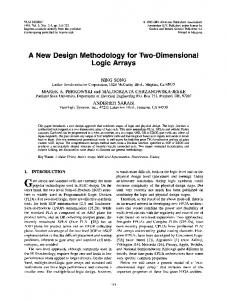
[email protected] Abstract We propose merged single-electron and MOS devices that serve as basic components of multiple-valued logic, such as a universal literal gate and a quantizer. We verified their operation by using single-electron transistors and MOSFETs fabricated on the same wafer by pattern-dependent oxidation process. We also discuss their application to an analog-todigital converter and a multiple-valued adder. Introduction Multiple-valued logics (MVLs) have potential advantages over binary logics with respect to the number of elements per function and operating speed (1-4). They are also expected to relax the interconnection complexity on the inside and outside of integrated circuits (2). Most MVL circuits have been fabricated with conventional transistors like MOSFETs (1,2) and bipolar transistors (3), or with negative-resistance devices represented by resonant tunneling diodes (4). However, their success has been limited, partially because the devices are inherently single-threshold or single-peak, and are not fully suited for MVL. In this sense, it is more natural to utilize the emerging single-electron devices (5,6) because the discreteness of electronic charge in a Coulomb island can be directly related to multiple-valued operation. Actually some single-electron MVL circuits have been proposed (7,8), but the operation has not yet been verified experimentally mainly because their schemes require unrealistic accuracy or limitations of device parameters and operating conditions. In this paper, we introduce a type of MVL circuit consisting of single-electron transistors (SETs) and MOSFETs for practical application. We demonstrate the operation of the basic components of MVL, such as a universal literal gate and a quantizer, using devices fabricated by the Si-based patterndependent oxidation (PADOX) process (9,10). The usefulness of the proposed single-electron MVL is discussed using an analog-to-digital converter (ADC) and a multiple-valued adder as examples. Principle of Operation Fig. 1(a) shows a schematic of the universal literal gate comprising a SET and a MOSFET. A MOSFET with a fixed gate bias of Vgg is used here to keep the SET drain voltage almost constant at Vgg-Vth, where Vth is the MOSFET threshold
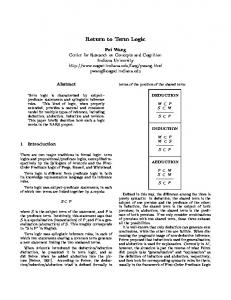
voltage. This results in the Id-Vin characteristics being independent of Vout [Fig. 1(b)], and sharp square-wave-like input-output characteristics with a large voltage swing [Fig. 1(c)]. Conventional SET inverters could not attain such characteristics because the voltage gain of a discrete SET is usually very small, and the applicable voltage is limited to sustain the Coulomb blockade condition. Figure 2(a) shows a schematic of the proposed quantizer. Periodic Id-Vgs characteristics of a SET can be converted to 2terminal Id-Vout characteristics when the SET gate and the MOSFET drain are shorted [Fig. 2(b)]. With a constantcurrent load Io, many stability points appear, and Vin fed through the transfer-gate MOSFET is quantized to a stability point after the gate is cut off. This results in the Vin-Vout characteristics shown in Fig. 2(c). Note that the number of periods in the universal literal characteristics [Fig. 1(c)] or voltage levels in the quantizer characteristics [Fig. 2(c)] is infinite in principle. This is a unique feature of the proposed SET-based MVLs, and leads to a considerable reduction of the number of devices in a circuit. Experiments Both the SET and the MOSFET were fabricated on a thin silicon-on-insulator (SOI) layer. A possible layout and the corresponding circuit diagram of the integrated SET and MOSFET are shown in Figs. 3(a) and (b). The SET is created in a narrow wire region by PADOX (9,10). The quantum size effect raises the potential in the wire, but in the middle of the wire the high compressive stress generated by the oxidation reduces the bandgap [Fig. 3(c)] (10). This creates two tunnel barriers and an island sandwiched between them, which constitute a SET. Since the areas outside the wire can easily be used for MOSFETs, PADOX is highly compatible with the CMOS process. Fig. 4 shows the Id-Vgs characteristics of a SET. Periodic drain-current peaks are clearly seen along with the effect of tunnel resistance modulation by the gate voltage. From this figure and a Coulomb diamond plot, gate capacitance Cg, source/drain capacitance Cs/Cd, and tunnel resistance were calculated to be 0.27 aF, 2.7 aF, and 80∼220 kΩ, respectively. The maximum voltage gain of the discrete SET (Cg/Cd) is as small as 0.1, but this presents no problem in constructing the merged SET-MOSFET device. Fig. 5 shows the subthreshold characteristics of a MOSFET fabricated on the same SOI wafer for drain voltages of 5 V
and 10 mV. The gate length, width and the gate oxide thickness are 14 µm, 12 µm and 90 nm, respectively. The device exhibits good cutoff and a small shift due to the drain voltage, which are suitable for the proposed applications. Fig. 6 shows the input-output characteristics of the proposed literal gate. When the SET Id-Vgs curve corresponding to the Vds assigned by the Vgg setting crosses the load line Io, the output switches between high and low levels as is seen in Fig. 6. The swing is sharp, and the amplitude of the swing is as high as 5 volts. Fig. 7 shows the 2-terminal Id-Vout characteristics of the SETMOSFET device with the SET gate shorted to the MOSFET drain. The current increases and decreases periodically, reflecting the Id-Vgs characteristics of the discrete SET. If we connect a current source of 4.5 nA, stability points a∼f corresponding to quantized levels should appear. Quantizer operation is verified with the setup shown in Fig. 8. The transfer-gate MOSFET1 and MOSFET2 for probing are connected externally. A triangular wave is fed to Vin, and the gate of MOSFET1 is driven by short pulses of CLK. The waveforms are shown in Fig. 9. Vout is quantized to levels a~f that correspond to stability points in Fig. 7. Operation speed shown in the figure is not limited by the intrinsic performance of the device, but by the large stray capacitance of 370 pF existing at Vout. Discussions Fig. 10 proposes a block diagram of a 3-bit flash ADC. 2 Whereas a conventional n-bit flash ADC requires n -1 components such as comparators, the SET ADC (11,12) requires only n components. In addition, this particular ADC with a quantizer at the front end and the SET-MOSFET literal gates does not require comparators, latches, or ramp generators at each literal gate. The use of Gray code is not necessary either, since the quantizer prevents the entry of intermediate voltage levels. Fig. 11 is a circuit diagram to realize the ADC in Fig. 10. The circuit is remarkably simple. For example, the main blocks except for the quantizer require only 9 transistors and 5 capacitors, which is half the 28 transistors required for a conventional implementation (1). Fig. 12 shows the block diagram of a full adder for redundant positive-digit number representation PD2-3 (1). The main parts of this adder are the same as that of the 3-bit ADC in Figs. 10 and 11. Thus, the number of elements can be reduced to a half by the use of the merged SET-MOSFET devices. In addition, this multiple-valued arithmetic itself has the merit of high-speed operation due to the elimination of carry propagation. Conclusions By combining a SET with a MOSFET, we made the best use of the periodic nature of the SET characteristics and obtained
a universal literal gate with sharp transfer characteristics and large output amplitude. We also verified the operation of a novel quantizer based on the same scheme. These basic components for MVL are extremely compact in that the former requires only three elements and the latter only four. Moreover, the number of periods or quantized levels is infinite in principle and does not affect the circuit size. With these components, we showed that a 3-bit flash ADC and a carry-propagation-free adder for redundant number representation PD2-3 could be made with half the number of elements in a conventional implementation. The results open up the possibility of constructing a new class of MVL with single-electron devices. Acknowledgments We thank Dr. Yukinori Ono for helpful discussions, and technical advice in electrical measurements. References (1) S. Kawahito, K. Mizuno, and T. Nakamura, "Multiple-valued currentmode arithmetic circuits based on redundant positive-digit number representations," Proc. 21st IEEE Int. Symp. on Multiple-Valued Logic, pp. 330-339, 1991. (2) T. Hanyu, M. Kameyama, and T. Higuchi, "Beyond-binary circuits for signal processing," Dig. Tech. Papers, IEEE Int. Solid-State Circuit Conf., TA 8.6, pp. 134-135, 1993. (3) L.J. Micheel, "Heterojunction bipolar technology for emitter-coupled multiple-valued logic in gigahertz adders and multipliers," Proc. 22nd IEEE Int. Symp. on Multiple-Valued Logic, pp. 19-26, 1992. (4) H.C. Lin, "Resonant tunneling diodes for multi-valued digital applications," Proc. 24th IEEE Int. Symp. on Multiple-Valued Logic, pp. 188-195, 1994. (5) J.R. Tucker, "Complementary digital logic based on the Coulomb blockade," J. Appl. Phys., vol. 72, pp. 4399-4413, November 1992. (6) M.A. Kastner, "The single-electron transistor," Rev. Mod. Phys., vol. 64, pp. 849-858, July 1992. (7) M. Akazawa, K. Kanaami, T. Yamada, and Y. Amemiya, "Multiplevalued inverter using a single-electron-tunneling circuit," IEICE Trans. Electron., vol.E82-C, pp.1607-1614, 1999. (8) Y. Suda, N. Shiotani, K. Imure, K. Hirohashi, and K. Yamamura, "Single-electron multiple-valued base-n full adder circuit using a bunch of electrons as a unit logic value," Abs. 2001 Silicon Nanoelectronics Workshop, pp. 32-33, Kyoto, June 2001. (9) Y. Takahashi, et al., "Size dependence of the characteristics of Si singleelectron transistors on SIMOX substrates," IEEE Trans. Electron Devices, vol. 43, pp. 1213-1217, August 1996. (10) S. Horiguchi, et al., "Mechanism of potential profile formation in silicon single-electron transistors fabricated using pattern-dependent oxidation," Jpn. J. Appl. Phys., vol. 40, pp. L29-L32, January 2001. (11) S.J. Ahn and D.M. Kim, "Asynchronous analogue-to-digital converter for single-electron circuits," Electron. Letters, vol. 34, pp. 172-173, January 1998. (12) Y. Mizugaki, Per Delsing, and T. Yamashita, "Single-electron flash analog-to-digital converter," The Japan Society of Applied Physics Spring Meeting, 30p-S-1, p. 211, March 2001.
Vdd
40 Id
Io Io
Vout MOSFET
Vgg
(b)
Id (nA)
Id
Vin Vdd
≈Vgg-Vth
Io
(a)
0
(c)
Fig. 1 (a) A schematic of the universal literal gate comprising a SET and a MOSFET. (b) Id-Vin characteristics, which are almost completely independent of Vout since the Vds of the SET is kept nearly constant at Vgg minus Vth, the threshold voltage of the MOSFET. (c) Expected transfer (Vin-Vout) characteristics.
Vdd CLK Id
Vin
Id
(b)
Vout
SET
≈Vgg-Vth
(a)
Vout
Vds
10-8 Vds= 5 V Vds=10 mV
10-12
(c)
(a)
0.5
Vin
Fig. 2 (a) A schematic of the proposed quantizer. (b) 2-terminal Id-Vout characteristics of the merged SET-MOSFET device with the SET gate shorted to the MOSFET drain. (c) Expected transfer (Vin-Vout) characteristics. Vin is transferred to Vout through the transfer gate MOSFET, and is quantized to a stability point after the gate is cut off.
high stress
5
10-6
10-10 transfergate MOSFET
4
10-4 Io
Vout MOSFET
Vgg
3 Vgs (V)
Fig. 4 Id-Vgs characteristics of a SET fabricated by the PADOX process, measured at 27 K. From this figure and a Coulomb diamond plot, gate capacitance Cg, source/drain capacitance Cs/Cd and tunneling resistance are calculated to be 0.27 aF, 2.7 aF and 80~220 kΩ, respectively.
stability points
Io
2
Vin
Id (A)
SET
10
Vout
Vin
Vds
30 Vds(mV) 15 10 20 5
1
1.5 2 Vgs (V)
2.5
3
Fig. 5 Id-Vgs characteristics of a MOSFET fabricated on the same SOI wafer as the above SET, measured at 27 K. Effective channel width, length and gate oxide thickness are 12 µm, 14 µm and 90 nm, respectively. Threshold voltage Vth, corresponding to Id=4.5 nA and Vds=3 V, is 1.07 V, and transconductance Gm at Vds=Vgs=3 V is 151 µS.
gate poly-Si
potential
(c)
silicononinsulator
strain effect
quantum size effect
(b) SET
MOSFET
position
Fig. 3 (a) A possible layout of the integrated SET and MOSFET. (b) Circuit diagram corresponding to the layout above. (c) Potential profile along the length of the narrow wire where a SET is created by the pattern-dependent oxidation (PADOX) (9,10). Since areas outside the wire can readily be used for MOSFETs, PADOX is highly compatible with a CMOS process.
Vout (V)
5 4 3 2 1 0 2
3 Vin (V)
4
5
Fig. 6 Measured transfer (Vin-Vout) characteristics of the proposed literal gate comprising a SET and a MOSFET [Fig. 1(a)] with Vgg of 1.08 V and a current load of 4.5 nA. Originally, the SET Id-Vgs characteristics have a large Vds dependence as indicated in Fig. 4, and this Vds dependence is alleviated by the MOSFET, resulting in a large voltage swing and sharp rises and falls.
8
I (nA)
7
stability points a
b
c
d
quantizer
e
Vin
f
Vm
capacitive divider
6
D0
2C
C
5
literal gates
D1
Io
4
2C
0 1 2 3 4 5 6 7
C
3
D2
2
C
2
3 V (V)
4
5
Fig. 7 2-terminal Id-Vout characteristics of the merged SET-MOSFET device with the SET gate shorted to the MOSFET drain, measured at 1.08 V of Vgg. Stability points (a~f) expected for the current load of 4.5 nA are also shown.
0 1 2 3 4 5 6 7 Vm
Fig. 10 A block diagram of a 3-bit flash ADC. A conventional n-bit flash 2 ADC requires n -1 components, whereas the SET ADC (11,12) requires only n. In addition, this particular ADC with a quantizer at the front end and with the SET-MOSFET literal gates does not require comparators, latches or ramp generator at each literal gate. The use of Gray code is not necessary either. D0
Vdd
Pulse Generator Sync HP8110A Function Generator HP33120A
CLK
Io
Vdd2 external MOSFET2
external MOSFET1
Vdd
CLK M3
M5
M7
M9
M1
M2
M4
M6
M8
SET1
SET2
SET3
SET4
Vout 2
MOSFET R SET
2C
Vss2
Oscilloscope HP5450C
D2
Vin
Vout
Vin Vgg
D1
2C
C
C
Fig. 8 Measurement setup for the quantizer proposed in Fig. 2(a). The external MOSFET2 is used as an FET probe to measure the Vout sustained by a small current (~nA).
C
Fig. 11 A circuit diagram of the 3-bit ADC in Fig. 10. Depletion-mode MOSFETs, M2, 4, 6 and 8, keep the drain voltage of the SETs nearly constant at the absolute threshold voltage, and other depletion-mode MOSFETs, M3, 5, 7 and 9, serve as current sources.
Example:
3 Y2 3 X2
2 Y1 2 X1
2 Y0 3 X0
6 Vm2
4 Vm1
5 Vm0
CLK
S=1•24+2•23 +1•22+0•2+1 =37
Vout
1 1 S4
Fig. 9 Quantizer operation measured by the setup in Fig. 8, with Vgg of 1.08 V and a current load of 4.5 nA. Operation speed is not limited by the intrinsic performance of the device, but by the large stray capacitance of 370 pF existing at Vout.
1 2 S3
0 0 1 S2
1
0
0 1 2 3 4 5 6 7 V
Y=3•22+2•2+2 =18
0 1 2 3 4 5 6 7 Vm1
f e d c b a
Vin
0 1 2 3 4 5 6 7 Vm2
X=3•22+2•2+3 =19
0 0 S1
1 S0
Fig. 12 A full adder for redundant positive-digit number representation PD2-3 (1) consisting of three ADC blocks without a quantizer and linear sums (⊕). This is free from carry propagation, and is thus high-speed. By using the merged SET-MOSFET devices, multiple-valued logics of this kind can be made with half the number of elements in conventional implementation.