Generating Test Plans for Acceptance Tests from UML Activity Diagrams Andreas Heinecke, Tobias Br¨uckmann, Tobias Griebe, Volker Gruhn Applied Telematics and e-Business Group University of Leipzig, Department of Computer Science Klostergasse 3, 04109 Leipzig, Germany
[email protected]
Abstract The Unified Modeling Language (UML) is the standard to specify the structure and behaviour of software systems. The created models are a constitutive part of the software specification that serves as guideline for the implementation and the test of software systems. In order to verify the functionality which is defined within the specification documents, the domain experts need to perform an acceptance test. Hence, they have to generate test cases for the acceptance test. Since domain experts usually have a low level of software engineering knowledge, the test case generation process is challenging and error-prone. In this paper we propose an approach to generate high-level acceptance test plans automatically from business processes. These processes are modeled as UML Activity Diagrams (ACD). Our method enables the application of an all-path coverage criterion to business processes for testing software systems.
1
Introduction
Testing is a crucial action throughout the complete lifecycle of software systems. The different phases of a software life-cycle involve different groups of stakeholders whose knowledge and understanding of software engineering differs heavily. This is especially true if software architects and domain experts talk about the software system. The software architect constructs the system design specification documents depending on the requirements stated by representatives of the customer’s group, namely, domain experts. The software architect has extensive knowledge about the software engineering process, while the domain expert has extensive knowledge about the functional domain but low level of knowledge or none knowledge about software engineering. As a suitable level of abstraction used to talk about a software system, software architects employ the Unified Modeling Language (UML) which de facto is the standard of
the software industry. The models created with UML usually constitute a big part of the software system’s specification documents. The specification documents are created during the initial phases of the software process to record early design decisions and stated requirements. They exist alongside the software product, serve as guidelines during the phase of implementation and are part of the documentation as well as a deliverable on completion of the product. Even though the specification documents are used to communicate the design progress of the system, the domain experts struggle to understand the contained models of the software system. At the latest, on the time of delivery of the whole software system or at the time of delivery of fixed milestones, the domain expert needs to perform an acceptance test to verify the completeness and correctness of agreed functions. Hence, the domain expert needs to test the system, and, therefore, he needs to create the respective test cases. It is obvious that the better the test cases reflect the real usage scenario of the system, the better the quality of the result. Therefore, the test cases should be closely related to the software specification. This can be achieved if the test cases are generated from the software specification. Since a domain expert usually has a low level of software engineering knowledge, in particular, software testing knowledge, he is likely to have difficulties with the task to derive test cases from the specification documents which are predominantly UML diagrams. This can lead to an unstructured test case generation process and cause several effects. The test cases do not cover the functionality that is to be tested, and, therefore, the results are insufficient. Furthermore, the test case generation process may be not repeatable. All in all the acceptance test can become inefficient and therefore expensive. In this paper we propose an approach which enables the domain expert to generate high-level acceptance test plans automatically from the software specification documents. The approach regards the testers viewpoint as relevant one and focusses on the workflows of modeled business pro-
cesses. We assume the business processes are modeled as UML Activity Diagrams. First, the user interaction steps within the workflow are marked with the role of the user that executes these steps. A user interaction step is any input a user states to the system or any output a user can expect from the system. In a second step the UML Activity Diagrams are transformed into an Interaction Flow Diagram (IFD) that contains only user interaction steps. Thirdly, the IFD is transformed into an Interaction Flow Graph (IFG). The IFG is directed graph that contains all paths of the IFD. In the fourth step the test cases are generated and assembled to test plans. A test plan contains all test cases to test the system. Each test case contains the proper instructions for a tester (in this case the domain expert) to execute it step by step. Furthermore, the test plan contains for each test case the inputs a tester has to provide to the system and the corresponding outputs to be expected from the system. Due to the fact that our approach makes only a few and rather less restrictive demands on the modeling of business processes, the freedom of modeling is kept. The paper is structured as follows: Section 2 gives an overview of the related work to the proposed approach. While there are many approaches that synthesize test cases from UML diagrams, we arranged them in groups and discuss each approach within the group. Section 3 presents our contribution for generating test plans from UML Activity Diagrams (ACD), which can be considered new to existent approaches, but still in an early stage of maturity. Section 4 concludes this paper and outlines the fields of future work.
2
Related Work
In this section we summarize a number of recent research approaches to generate test cases from UML diagrams. Each approach is presented by describing the intention, classifying the abstraction level of the generated test cases, outlining the rough procedure, and discussing the relation to our approach. As there are quite a lot of contributions focusing on the test case generation from UML Diagrams, we categorised the approaches into the following groups: Activity Diagram based approaches, State Machine based approaches, and hybrid approaches. Test Case Generation from Activity Diagrams The approaches presented here focus on the generation of test cases from UML Activity Diagrams. The presented approaches are closely related to our approach since they utilize UML Activity Diagrams as well. The approach presented by Kim et al. [12] adopts the testers’ viewpoint and therefore focuses on the inputs to the system and the outputs from the system. The test cases are derived from a constructed graph. Applying the single stimulus principle helps preventing the state explosion problem.
Similar to our method, the testers’ viewpoint is regarded as relevant. Even though this approach generates valid highlevel test cases, the whole process is considered to be executed manually. Our approach focuses, a strong tool support and is validated by a tool prototype. Furthermore, the approach by Kim et al. [12] involves no role model, which allows mapping operation steps to the corresponding group of users. The presented method is rather embryonic and lacks the tool support. Furthermore, we did not find any evidence of further research activity on that topic. Chen et al. [4] propose an automatic test case generation approach that focuses on generating unit level test cases. The proposed approach does not derive test cases directly from the UML Activity Diagrams. The authors argue that the direct test case generation from Activity Diagrams requires complex algorithms due to the fact that the branches and loops within these models make the path conditions very complicated. By the approach it is intended to avoid this drawback of the state of the art of UML modelbased testing. In this approach at first numerous test cases are generated randomly, and then the generated test cases are utilized to run the software. While running the software with the generated test cases, the program execution traces are elicited. The program execution traces can be used in two ways. First, they can be utilized for comparison with the UML Activity Diagram paths to determine the correctness of the implementation. Secondly, they are utilized for the derivation of a reduced set of test cases matching a defined test adequacy criterion. While our approach targets high-level system test cases, the approach of Chen et al. [4] targets low-level unit test cases. This means by the method of Chen et al. [4] it is intended to determine the correctness of algorithms and the correct interaction of classes, whereas by our approach it is intended to determine the correct support of workflows of business processes. Besides the substantial differences regarding the intention of the two approaches, the presented method by Chen et al. [4] contains some remarkable drawbacks as it restricts the modeling and implementation. For instance, the approach regards each action within the used Activity Diagrams as method call, which is a restrictive requirement regarding the modeling. In addition to that, the approach cannot differentiate between method calls to different instances of a class. Hence, it is required that each class of the system under test has only a single instance, which is a restrictive requirement regarding implementation. Test Case Generation from State Diagrams The approaches presented here focus on the generation of test cases from UML State Diagrams. They differ from our contribution in that way that they utilize a different diagram type to synthesize test cases from. Just using another behavioral diagram for test case generation is certainly not a wide
difference. The main difference is located in the semantic foundation of both diagram types. The semantic foundation of UML State Charts introduced with UML 2.0 is more formal than the semantic foundation of Activity Diagrams [6]. Furthermore, State Charts describe the behaviour of the system from another view. Riebisch et al. [17] propose an approach to generate statistical system level test cases from the specification of requirements. They aim at statistical reliability detection rather than fault detection. The test case generation method is integrated into an iterative software development process, and an XML-based tool supports the application of the method. The generated test cases can be executed either manually or automatically with the help of test tools. The aim of the approach is to bridge the gap between requirements engineering and reliability engineering. The test case generation method is organized in five steps: First, the definition and refinement of use cases is to be done manually. The refinement of the use cases is inspired by the approach of Cockburn [5]. Second, the refined use cases are transformed into state diagrams. The transformation is inspired by the work of Fr¨ohlich et al. [10]. Third, the generated state diagrams are transformed into usage graphs. A usage graph is a directed graph with a single start, a single final node, and several usage states. The usage states that are connected with transitions which are labelled with the causing user actions. In the fourth step, the usage graphs are transformed into usage models. A usage model resembles an UML State Diagram. The central activity during this step is to determine the probability of each transition; this has to be done manually. The result is a usage profile describing how the software system can be utilized by different users. The usage model resembles a Markov chain since the procedure is inspired by the work of Whittaker et al. [19]. Finally in the fifth step the test cases are generated from the usage models. Even though the approach of Riebisch et al. [17] is similar to our approach concerning the generation of high level system test cases, it nevertheless represents a different field of software testing. While we intend to determine the support of workflows of business processes by a software, Riebisch et al. [17] intend to determine the reliability of the system under test. In comparison to our approach, the method of Riebisch et al. [17] requires more additional manual actions carried out by the tester than our approach does (e.g., substantial refinement of use cases and determination of the probability of transitions within the usage profile). Fr¨ohlich et al. [10] propose an approach which generates system level test cases from UML Use Case Diagrams. Their approach targets specification based testing and effective test automation. A key feature is the traceability of requirements throughout the complete software life-cycle. The contribution of Fr¨ohlich et al. [10] was the first on
the particular topic of deriving test cases from use cases by transforming them to UML State Diagrams. As mentioned above, the method of Riebisch et al. [17] utilizes this transformation, too. The test case generation process comprises two general steps. First, the use cases are transformed to UML State Diagrams. Thereby, each element of the use case is mapped to the UML State Diagram. Second, test cases are derived from these diagrams. In order to generate test cases, the authors transform the test case generation problem into an AI planning problem, which can be solved with STRIPS [9], a fundamental AI planning system. Although this approach generates valid high-level system test cases, the procedure involves an extensive additional effort for the tester. For instance, to reach the traceability of the requirements throughout the whole software life-cycle the tester has to define how each part of the requirements specification impacts the downstream artifacts. Kim et al. [13] the application of state diagrams for class testing is discussed. The approach does not address highlevel tests but low-level tests of classes. The test cases are derived from UML State Diagrams satisfying a set of coverage criteria based on control and data flows. In Gnesi et al. [11] an approach for formal test case generation from UML state charts is proposed. It is based on input-enabled transitions systems with transitions labelled by input/output pairs, which provide the semantic model for a behavioral subset of the state charts. Basically, the theoretical foundations of model-based formal test case derivation is addressed using formal conformance testing. The presented approach is rather formal and requires extensive knowledge about software engineering, especially inputenabled transition systems. Hence, the intentions of this contribution and our contribution are completely different. Hybrid Approaches In this paragraph another two related approaches are discussed. Both concentrate on the test case generation from UML diagrams but do not fit into the above introduced categories as they integrate the information of at least two UML diagram types. In the first of the two approaches, by Nebut et al. [15], integrated UML Use Case Diagrams and UML Sequence Diagrams are used to generate test cases. In the second approach, by Bertolino et al. [2], UML Sequence Diagrams and UML State Charts are utilized to derive Test cases. Nebut et al. [15] describe an approach to automate the generation of high-level system test scenarios for objectoriented embedded software. The authors intend to integrate formal methods with established software engineering practices to improve the feasibility of this approach for the industrial application. Their main contribution is the generation of test cases from a formalization of the requirements. The test case generation process itself is divided to two phases featuring a different level of automation. In
the first phase the requirements stated to the software system are modeled as UML Use Case Diagram. The modeled use cases are annotated with pre- and postconditions. The authors call this an requirement-by-contract approach analog to the design-by-contract approach by Meyer [14]. The annotated use cases are transformed by a tool into a simulation model. The model consists of correct sequences of use cases - the so called test objectives - and serves as input for a simulation. The results of the simulation are used to fix detected inconsistencies of the model. The second phase of the approach is the test scenario generation. The test objectives serve as input for this generation step. The transformation of test scenarios is related to the approach of Briand and Labiche [3]. The integration of use cases and the UML Sequence Diagrams refining these use cases enables to obtain test scenarios that are closely related to the implementation. This approach concentrates on highlevel system test cases as well as our approach. However, the main difference between our approach and this one is that the method presented by Nebut et al. [15] is tailored for embedded systems. Our approach focusses on information systems. A difference between information systems and embedded systems is that the state space of embedded systems is very limited compared to the state space of information systems. The simulation model that is built during the first phase is suited to clarify this issue. Applying this approach to information systems will result in a simulation model which complexity in building time and memory consumption is too high to be handled. Bertolino et al. [2] present an approach which integrates the information of UML Sequence Diagrams and UML State Diagrams. The integrated diagram serves as input for the test case generation. One of the main goals of this approach is the industrial application. Therefore, the authors name three demands that have to be met by an approach to enable industrial application. First, the approach has to cope with a software specification that is not formally defined, but semi-formal such as UML. Second, the testing must be supported within the early phases of software development, while the software specification is neither complete nor consistent. In other words, the approach must be applicable even if the system is only partially modeled. Finally, the approach must increase the test accuracy even if the test effort is reduced. The authors identify these demands as crucial regarding the feasibility for industrial application and argue that their contribution is new in this regard with respect to existent approaches. Basically, the test case generation approach comprises two aligned procedures. First, the information of Sequence Diagrams and the State Diagrams are integrated into a more complete model. This (reasonably) complete model is checked for inconsistencies, more precisely implied scenarios, with the help of the method by Uchitel et al. [18]. Second, test cases are synthesized from
this (reasonably) complete model. The test case generation utilizes the Use Interaction Test (UIT) method by Basanieri et al. [1]. The whole procedure is carried out in four steps. The approach by Bertolino et al. generates test cases that test the correct interaction of components or subsystems. In short, it generates test cases for integration tests. On the contrary, our approach generates high-level system test cases which test the system as a whole. Instead of testing the correct interaction of modules, we aim to test whether the workflows of business processes are supported correctly by the system under test. While our approach tests the system from the user’s viewpoint, the approach of Bertolino et al. tests the system under test from a rather technical viewpoint. Similarly to Bertolino et al., our method is able to generate test cases even if the system is only partially modeled. Only, the workflows which are to be tested have to meet a few requirements regrading their consistency.
3
Our Approach
In this section we will detail our approach, starting with a brief introduction to the requirements we state on activity diagrams (ACD) to be used as input for our generation method. Furthermore, we will describe the motivation for and the realization of the model transformation steps that have to be taken in order to derive test plans from business process workflows modeled as UML ACD.
3.1
Requirements on Activity Diagrams
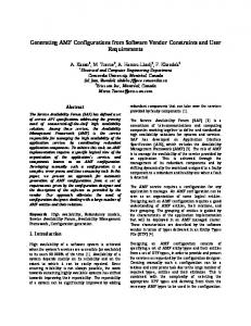
The most basic assumption is that the business processes, that are to be supported with the software are part of the software specification and therefore are modeled with a modeling language that provides formally defined syntax and semantics. At the moment, we assume that the workflows of business processes are modeled with the Unified Modeling Language. Other modeling languages with formally defined syntax and semantics, that support the modeling of business processes are suitable, too. But the actual prototype of the tool concentrates on the UML 2.0 standard. The Unified Modeling Language (UML) supports the modeling of processes and process related concepts in Activity Diagrams (ACD). With the use of ACDs, an abstract view onto the behavior of a system supporting the viewpoint of business processes can be modeled. For test plan generation, we suppose an abstraction level of ACD to provide rather a “functional system model” than a technical model; an example is given in Fig. 1. Furthermore, for the generation of test plans, the following (technical) requirements have to be met by ACDs: • Functions as well as decisions, which are manually executed (by a specific user role) are explicitly marked.
this, the ACD contains only (stereotyped) actions, decision nodes, join nodes, fork nodes, initial nodes, and final nodes.
ACD Expenses reports
3.2 Create expenses report Report
Report
Traveller
Fill form Report
[Save as Draft] [ Send to Accountant] Assign accountant
Report
Check validity Accountant [Report is invalid] [Report is valid] Report
Calculate refund Report Report
Transfer refund
Report
Traveller
Confirm Report
Figure 1. Example Activity Diagram This can be done with the note element that connects to the associated actions. The note contains the user role that executes this action as description. • All objects providing information to a manually executed function are modeled as input pins of actions. • Objects, which are manipulated are modeled as input pins and output pins of actions. • Objects, which are created during the execution of an action are modeled as output pins of actions. Before the ACD can be transformed into a diagram (Interaction Flow Diagram) that only contains interactions performed by the user, all activities have to be flattened. After
Making Inputs and Outputs Explicit
The description of a business process modeled with an UML Activity Diagram (ACD) tends to be very detailed. Such diagrams usually contain process steps which are related to a user and process steps which are executed transparently by the system. User related process steps are any kind of decisions or actions that require the user to state an input to the system or the system to provide an output to the user. In this paper, we regard the user’s or rather the tester’s viewpoint as the relevant one and, therefore, the system as black-box. In doing so, the user is only able to state inputs to the system and observe the corresponding outputs from the system. Compiling a workflow description containing all user related process steps from a certain business process, should enable a user to execute the business process with the workflow description on hand. In the following, we call such a workflow description test plan and the user executing the steps tester. A test plan contains proper instructions which input a user has to provide and which output is to be expected accordingly. With a test plan on hand a tester is able to verify the correct behaviour of a certain system under test (SUT) concerning the realization of the business process. From the testers viewpoint only process steps requiring input from the tester or providing output to the tester are relevant. Hence in order to compile a test plan, these process steps have to be found, marked and filtered. Therefore, we define a special type of diagram that contains only user related process steps, the Interaction Flow Diagram (IFD).
3.3
Interaction Flow Diagram
The Interaction Flow Diagram represents the control flow of inputs and outputs a tester has to state to the system and to expect from the system. Internal actions which are transparent for the tester are suppressed and are not part of the IFD. The IFD is characterized by a drastically reduced set of node types compared to the UML Activity Diagram and serves as initial point to compile a test plan. The Interaction Flow Diagram is regarded as an in-memory model which is exclusively used as an intermediate step to generate test plans. The IFD generally serves two purposes. First, it serves as the starting point to generate test cases from, since it contains only the user interaction steps. The reduced syntax makes the processing of the contained information rather simple compared to the UML Activity Diagrams. Second, the IFD serves as an abstraction layer. Although the approach currently exclusively focusses UML
Activity Diagrams, we plan to integrate more modeling languages that are suitable to model business processes.
ControlFlow * 1 Node
ControlNode
Associated User
Associated User Input Objects Object A Action
Object C
1 IFGNode
Output Objects
Object A Object B
Container
DecisionNode
Incoming Control Flow Arcs
*
*
1
InteractionFlowGraph
InteractionFlowDiagram
Possible Option
Action [X < Y]
Name of this User Action Outgoing Control Flow Arc
Figure 2. Elements of the Interaction Flow Diagram
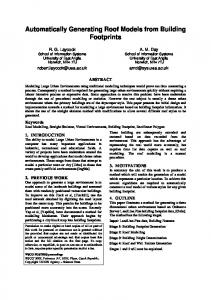
In Fig. 2 the elements of an Interaction Flow Diagram are outlined. Basically, there are only three groups of nodes: Initial nodes, Control nodes, and User Action nodes. The group of Initial Nodes contains the Start node and the Stop node. The User Action node group is formed by the Create Action, the Manipulate Action, and the Show Action. These three types of User Actions reflect the most basic interaction concepts. The Create Action involves the creation of a particular object. The Manipulate Action involves the modification of a particular object. The Show Action involves presenting a particular object to the user. The group of Control nodes contains only the Decision node at the current state of realization. More Control nodes like Fork and Join nodes which require a more advanced handling during model transformation are left out for the sake of simplicity. All nodes contained in an Interaction Flow Diagram are vertically connected via control flow arcs. Start and Stop nodes are equal in syntax and semantics to Start and Stop nodes in UML Activity Diagrams. User Actions are depicted as rectangles with a name and a stereotype denoting the user role. Object flows Input and Output objects are represented as horizontal arrows heading to or away from the User Action. Decisions that are depicted as ellipses are also labelled with a stereotype displaying the user role associated with this decision. A Decision node of the IFD has at least two outgoing arcs and one incoming arc. The sequence of User Actions and Decision nodes represents the interaction control flow. Each notation element of the Interaction Flow Diagram is annotated with a user role. This role provides the information which user group is intended to execute this action or decision. This feature is to a lesser extend important to assign the correct group of testers to the actions in order to execute them, but rather to inform the tester in which context an action is to be executed. Of course a tester is able to take over more than one role during testing the system.
InitialNode
CreateAction
StartNode
StopNode
ShowAction
ManipulateAction
Figure 3. Metamodel of IFD and IFG
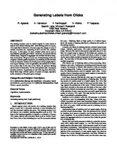
As a prerequisite of the transformation from a UML Activity Diagram (ACD) to an Interaction Flow Diagram (IFD), the concerned Activity Diagrams need to be flattened to atomic actions. The corresponding mapping rules are as outlined in Fig. 5 and described as follows: Each action that is associated with a user (stereotype “role”) is mapped into a User Action within the IFD. The name of the ACD action is used as name of the User Action in the IFD and the modeled user role is mapped to the associated user of a User Action. If an action in the UML Activity Diagram has any input parameter, it is transformed into Input Objects of User Actions in the IFD as well as each output parameter in UML is mapped into an Output Object in IFD. (1) illustrates the mapping rule for an UML ACD Action with input and output parameters, (2) and (3) show the mapping of UML Actions with either an input pin or an output pin. (4) All decisions that are relevant for the control flow through the UML ACD and which are associated with a user are mapped into a IFD Decision. Comparable to User Actions, the associated role is noted in the Decision element and all outgoing control flow arcs in the UML ACD are mapped to the outgoing arcs of the IFD Decision. (5) The control flow arcs between user associated UML Actions are transformed into Control Flow Arcs of the IFD between IFD User Actions. (6) If the successor of an UML Action is not associated with an user (this action is done automatically by the system), the next manually executed action becomes the successor in IFD. As an example: because “Action 2” has no assigned user role, “Action 3” becomes the successor of “Action 1” in IFD. This is due to the fact that an end user can only verify the functions provided by the user interface, which excludes internal functions. To explain the transformation of an Activity Diagram to an Interaction Flow Diagram and further steps of our generation process, we introduce the expenses report example
UML Activity Diagram (1)
Interaction Flow Diagram
Object
«role» User 1
Object
Action
«User 1»
Object
Action
Object
Manipulate Node
(2)
Object
«role» User 1
Object
Action
«User 1»
Action
Show Node
(3)
«role» User 1
Interaction Flow Diagram
«User 1»
Action
Object
Action
Object
Creation Node
(4)
«role» User 1
«User 1»
[X >= Y]
[X < Y]
[X >= Y]
C1
«Traveller»
Report
«Traveller»
Report
Create expenses report
[X < Y]
User Decision Report
(5)
«role» User 1
«User 1»
Action 1
M1
Object Object
«role» User 1
Object
Action 2
«User 1»
Fill form
Object
Action 1
[Save as Draft]
Object
Action 2
D1
Object
«Traveller»
[Send to Accountant]
(6)
Object
«role» User 1
Object
Action 1
«User 1»
Object
Report
Action 1
«Accountant»
Report
Check validity
Object
M2 Object
Action 2
«User 1»
Action 3
[Report is invalid] «Accountant»
Object
Object
«role» User 1
D2 [Report is valid]
Action 3
Report
Figure 4. Mapping Rules from UML Activity Diagram into Interaction Flow Diagram
M3
Report
S2
pictured in Fig. 1. The UML Activity Diagram (ACD) shows the business process of creating an expenses report. A traveller creates a new report form, fills in the form, and saves this report as draft for further editing or decides to submit this form. An accountant will process the travellers report and decide to refund the travellers expenses or to send the report back to the traveller for revision. The ACD contains all necessary information and therefore is prepared for the transformation to an Interaction Flow Diagram (IFD).
Report
«Accountant»
Report
Calculate Refund
«Accountant»
Transfer Refund
«Traveller»
Report
Confirm
M4
Figure 5. Interaction Flow Diagram
3.4
Interaction Flow Graph
Prior to deriving test cases all paths of the Interaction Flow Diagram conforming to a selected coverage criterion are mapped to a graph. This graph is called Interaction Flow Graph (IFG) and provides the foundation for the test plan generation process. The IFG is a directed acyclic graph.
Even though the Interaction Flow Diagram can contain cycles, the Interaction Flow Graph is free of any cycle to ease the tree traversal. The absence of any cycle in the IFG is achieved by applying a modified Depth-First-Search (DFS) algorithm, which ensures that each cycle and each combination of cycles, if there are any nested cycles, are executed only once. The basic concept of this algorithm is the cycle protection. The cycle protection prevents the recursive algorithm to traverse the same cycle twice while building a path for the IFG. The Interaction Flow Graph is built by a subset of node types of the Interaction Flow Diagram, because not all nodes are required here. Since the Interaction Flow Graph and the Interaction Flow Diagram are based on the same metamodel, the mapping of nodes from IFD to IFG is easy. Basing both IFD and IFG on the same metamodel ensures that no information that is associated with a particular node will be lost during transformation. Essentially the Control nodes are not mapped to the IFG. The Interaction Flow Graph is a directed graph and each path in this graph represents a sequence of inputs and outputs to traverse a particular business process. Hence, if the IFD contains a cycle, the nodes associated with this cycle will appear more than once in the IFG. For the business expenses example we select the allpaths-coverage criterion. The example contains two cycles of which the first cycle is a nested cycle. The first cycle starts with the transition from Decision D1 to “Fill Form” and the second one leads from Decision D2 to “Fill Form”. Due to the fact that the second cycle includes the start of the first cycle, the first cycle is nested in the second cycle. Nested cycles lead to the effect that each combination of execution of the cycles results in a distinct path. Usually the application of the all-paths-coverage criterion to a process with nested cycles is complex since the traversing algorithm risks to run into one of the cycles. As mentioned above, we employ a modified Depth-FirstSearch algorithm to walk through the Interaction Flow Diagram. Essentially, our algorithm inspects the nodes and their successors of the IFD and marks each visited node and cycle in order to avoid running into a loop. In doing so, each node that is a subtype of IFGNode is put into the graph. Fig. 7 shows the example Interaction Flow Graph derived from the Interaction Flow Diagram illustrated in Fig. 5. The Interaction Flow Graph now contains all paths derived from the Interaction Flow Diagram. These paths are extracted and analyzed. To extract these paths, a feasible algorithm must be applied. Since the graph contains no cycles by definition, there are many feasible algorithms to extract the paths from the graph, e.g., Breadth First Search, or Depth First Search. Depending on the number of Decision nodes and nested cycles contained in the Interaction Flow Diagram, the num-
Figure 6. Applied Modified Depth-FirstSearch Algorithm
C1
M1
M2
M1
M1 M2 M3
M1
M3 M2
M2
M1 S2
S2
M3
M2 M4
M4
M3
S2
M3 S2
S2 M4
M4
M4
Figure 7. Interaction Flow Graph
ber of paths extracted to the IFG can be quite huge. As Fig. 7 shows, our algorithm found five paths for the expenses report example. We call each path a test scenario and each single testing step within a scenario a test case.
3.5
Role Traveller
Testcase ID TC1
Input Output Create Expenses Show Expenses Report Report
Traveller
TC2
Fill Form
Traveller
TC3
Fill Form
Accountant
TC4
Calculate Refund Transfer Refund
Construct Test Plans
The final result of the test plan generation is a humanreadable representation of a test plan. A domain expert is now able to process a (technical) structured acceptance test without having explicit knowledge about testing softwaresystems. The generated test plan guides the domain expert who has to check whether the system behaves as expected or not through the system. In Fig. 8 and Fig. 9, the tester is provided with instructions what is to be done. The output shows five test scenarios with thirty-five test cases. Each test case is presented with the information, which user role executes this process step, what is to be done, and what is to be expected. In the first test scenario, the tester with the role “Traveller” has to “create expenses report” and expect “fill form” to be shown. In the next step, the tester with the role “Traveller” has to “fill form” and decide to “send to accountant”. Before the tester with the role “Traveller” can “confirm” the calculated refund. The tester with the role “Accountant” has to “check validity” of the report and decide that the “report is valid”. Afterwards the tester with the role “Accountant” has to “calculate refund” and expect the “transfer refund”. This simple example shows that the generated test plan provides simple instructions for a tester to execute a business process with the system under test. The tester is guided through the testing process and can ensure that the selected coverage criterion is applied. While the tester is guided through each path of the business process, it can be verified if the system behaves as specified or not.
4
1.1 Test Scenario 1
Conclusion
In this paper we presented an approach to generate highlevel acceptance test cases from business processes, that are modeled as UML Activity Diagrams. We regard the system under test as a black box, and, therefore, the tester’s viewpoint as relevant. This is accomplished by concentrating on inputs a tester makes to the system and outputs a tester can observe from the system. To process such inputs and outputs, we apply several model transformation steps. A first step transforms the business process to an intermediate model called Interaction Flow Diagram (IFD). The next step creates a graph that contains all paths from the intermediate model. From this graph we derive the test cases that are assembled in test plans. The test plans structure and guide the testing activities and therefore support the domain
State: Filled All required fields of the report are filled. Procedure: Manipulate
Traveller
TC5
Confirm
Action: Fill Form Enter itinerary, specify bills and receipts Validate: Figure 1.1.1 Testcase8.1 Example of a generated Decision: Send to Accountant; Save as Draft nario summarized within a table. Save as draft if not all documents are received. Role: Traveller Input: Assign to accountant if report is complete.
Summary Create Expenses Report; validate output Report; expect Show Expenses Report Fill Form; provide input Report; validate output Report; Send to Accountant; Fill Form; provide input Report; validate output Report; Send to Accountant; Calculate Refund; provide input Report; validate output Report; expect Transfer Refund Confirm;
test sce-
Output: Report Expect: Procedure: Create Create Expenses Report 1.1.3Action: Testcase 3 User creates a expenes report. Validate: Role: Traveller Decision: Input: Report Expect: Show Expenses Report
State: Invalid
1.1.2 Testcase 2 A report is invalid if e.g. not all required documents of the report are received. Output: Report
Role: Traveller Input:State: ReportFilled All Draft required fields of the report are filled. State: Procedure: The report isManipulate saved as draft. Output: Report Fill Form Action:
Enter itinerary, specify bills and receipts Page 2 Validate: Decision: Send to Accountant; Save as Draft Save as draft if not all documents are received. Assign to accountant if report is complete. Expect:
1.1.4 Testcase 4
Figure 9. Example of a generated test case Role: Accountant with detailed information. Input: Report State: Valid All required fields of the report are filled properly. Output: Report State: Calculated expert during the acceptance test. Since our approach analThe refundbusiness of the reportprocesses, is calculated. only the information that yses modeled Procedure: Manipulate is modeled can be included in the test plans. Therefore, the Action: Calculate Refund
modeled business provide rather detailed The amount processes of the refundingshould will be calculated. Validate: Furthermore, the approach focusses the test information. of functional requirements. Even though we focussed this Page 3 is also fitted to suppaper on acceptance tests, the approach port the system test. However, one advantage over other approaches is that it enables domain experts that have none or less software engineering knowledge to generate test cases for the acceptance test from the software specification on their own. To prove the proposed method, we implemented a prototype that is able to import a business process modeled as UML Activity Diagram, apply all transformation steps on
that diagram and assemble the respective test plans. Fig. 8 and Fig. 9 are showing two details of a generated test plan which was generated by the implemented prototype. Fig. 8 shows the table that summarizes all test cases of a certain test scenario. Fig. 9 shows a sample of the detailed description of the test case. This detailed description provides the structured information how the tester has to interact with the system. It details which input the tester has to provide, which output is to be expected and what actions the tester has to take. The prototype is implemented as an Eclipse plugin [7] using EMF [8] - the Eclipse Modeling Framework. The prototype is able to import UML Activity Diagrams that are exported as XMI [16] - the XML Metadata Interchange format file. XMI is the most popular format for exchanging UML models. Although our approach is still in an early stage of maturity, the tool prototype shows the general feasibility of the proposed method. Furthermore, we believe that the method is valuable contribution to the improvement of test efficiency. Our long-term objective is to advance this procedure to a method that specifies the generation of test cases that can be executed automatically within a test harness. We are addressing the issue of test automation within a research project that focusses on testing web-based information systems. Therefore, we have to address several concerns like, the correct handling of fork and join nodes during model transformation, the integration of object states and the user actions, and the selection of valid test data. A further field for future work is the integration of other modeling languages that are suitable to model business processes.
References [1] F. Basanieri, A. Bertolino, and E. Marchetti. The cow suite approach to planning and deriving test suites in uml projects. Lecture notes in computer science, Jan 2002. [2] A. Bertolino, E. Marchetti, and H. Muccini. Introducing a reasonably complete and coherent approach for modelbased testing. Electronic Notes in Theoretical Computer Science, 115:85–97, Jan 2005. [3] L. Briand and Y. Labiche. A uml-based approach to system testing. Software and Systems Modeling, Jan 2002. [4] M. Chen, X. Qiu, W. Xu, L. Wang, J. Zhao, and X. Li. Uml activity diagram-based automatic test case generation for java programs. The Computer Journal, Jan 2007. [5] A. Cockburn. Structuring use cases with goals. Journal of Object-Oriented Programming, Jan 1997. [6] D. Drusinsky. Modeling and Verification Using UML Statecharts: A Working Guide to Reactive System Design, Runtime Monitoring and Execution-based Model Checking. Newnes, 2006. [7] Eclipse Foundation. Eclipse. Eclipse Foundation, 2009. [8] Eclipse Foundation. The Eclipse Modeling Framework (EMF) Overview, November 2009. Available online at: http://www.eclipse.org/modeling/emf/.
[9] R. Fikes and N. Nilsson. Strips: A new approach to the application of theorem proving to problem solving. Artificial intelligence, 2nd IJCAI, Jan 1971. [10] P. Fr¨ohlich and J. Link. Automated test case generation from dynamic models. ECOOP 2000, Lecture notes in computer science, pages 472–491, Jan 2000. [11] S. Gnesi, D. Latella, M. Massink, and C. ISTI. Formal test-case generation for uml statecharts. Proceedings of the Ninth IEEE International Conference on Engineering Complex Computer Systems, pages 75–84, Jan 2004. [12] H. Kim, S. Kang, J. Baik, and I. Ko. Test cases generation from uml activity diagrams. Eighth ACIS International Conference on Software Engineering, Artificial Intelligence, Networking, and Parallel/Distributed Computing, pages 556 – 561, 2007. [13] Y. Kim, H. Hong, D. Bae, and S. Cha. Test cases generation from uml state diagrams. IEEE Proceedings-Software, 146(4):187–192, Jan 1999. [14] B. Meyer. Applying’design by contract’. IEEE Computer, Jan 1992. [15] C. Nebut, F. Fleurey, Y. L. Traon, and J.-M. Jezequel. Automatic test generation: A use case driven approach. IEEE Transactions on Software Engineering, 32(3), Jan 2006. [16] OMG. XML Metadata Interchange (XMI). OMG, 2007. [17] M. Riebisch, I. Philippow, and M. G¨otze. Uml-based statistical test case generation. Lecture notes in computer science, Jan 2003. [18] S. Uchitel, J. Kramer, and J. Magee. Incremental elaboration of scenario-based specifications and behavior models using implied scenarios. ACM Transactions on Software Engineering and Methodology, 13(1):37–85, Jan 2004. [19] J. Whittaker and M. Thomason. A markov chain model for statistical software testing. IEEE Transactions on Software Engineering, 20(10):812 – 823, Jan 1994.