Année académique 2008-2009
Working paper 09/12
Generating user interface from task, user and domain models
Vi Tran, Jean Vanderdonckt, Manuel Kolp, Stéphane Faulkner
Site de Louvain-la-Neuve - Place des Doyens, 1 - 1348 – Louvain-la-Neuve
Generating User Interface from Task, User and Domain Models Vi Tran, Jean Vanderdonckt, Manuel Kolp
Stéphane Faulkner
Louvain School of Management-PRISME Université catholique de Louvain Louvain-la-Neuve, Belgium
[email protected]
Louvain School of Management-PRISME University of Namur Louvain-la-Neuve, Belgium
Abstract— Researchers have greatly studied the importance of automatic database user interface generation based on declarative models. The task, domain and user models are three important declarative models on which the user interface can be built. This paper then proposes a framework, i.e., a methodological process and a software prototype to drive the automatic database user interface design and code behind generation from the task, user and domain model combined together. This includes both the user interface and the sound and complete data update, definition and manipulation. The case study used in this paper is Translogistic, a project supported by the Walloon Region that aims to develop a highly capable, competitive and complete combined transport as well as a high value quality logistics. Keywords-Task Model, Domain Automatic Generation, User Interface
I.
Model,
User
Model,
INTRODUCTION
Research works on UI have richly discussed the capability and importance of automatic user interface generation and propose them as the core of visual-based development environments [16]. Specifically, user interfaces for data systems have been a technical and human interaction research question since a long time and today these UI require dynamic automation and run-time generation to properly be dealt with on a large-scale. There are currently numerous and various approaches using different input materials: designs, patterns, architectures, declarative models to generate UI. In this set of techniques, an emerging method is the automatic UI generation from declarative models [1, 3, 6, 9], inspired from Fourth Generation Languages code generation [2, 5, 7]. In practice, these models are high-level abstraction such as goal or task [1], pattern [14], presentation, dialogue [4] or interaction, domain [8] models. The high-level abstraction features provided by these declarative models typically reduce the semantic gap between the software and organizational concepts. The information used to build the user interface usually comes from a large and complex context in which the users work to complete their tasks. This context includes the users’ characteristics (user model), their current domain of
application (domain model often linked in the database world to the data or conceptual model), the tasks they commonly perform (task model), the platform they work on (platform model), the device [17] they are currently using (device model) and so on. This context is not fixed for the all the user interface generating processes since it depends on the different approaches. The task, domain and user models are three important models based on which the user interface can be built easily for the following reasons in the context of human computer interaction: The task model describes the abstract user interface. The task model is used as a single representation for the user interface that can be used to generate the UIs for different modalities and platforms. The domain model provides the special features for creating a user interface. These features are the attributes of the objects in domain model and the relationships between these objects. The domain model is not used separate from other models to generate the user interface, it is combined to the task, application, domain, user, dialog models. The user model supports the creation of user interfaces which consider to the preference of the users. Like the domain model, the user model is not used separate from other models to generate the user interface since there are various aspects of the user interfaces adapted according to user models. Combining models is an important concept in user interface generation since the different models describe different aspects of the UI. For example, a user interface generated from a task model is expected to be a means on which the user can communicate with the system to accomplish his task. The user interface generated from a user model is expected to support the users based on their characteristics. The user interface generated from several different models carry many needed aspects of a user interface. Various research works have focused on such models to generate UIs. For instance, TOOL[10] uses the task and user models to generate the UI. The UI is automatically generated from the domain and use case models [18] and from combining task, domain and presentation models [8]. This research hence proposes a framework, i.e., a methodological process and a software to drive the automatic database user interface design and code behind
generation from the task model, user model and domain model combined together. The main difference in our work from other ones is the combination of these three major models and the generation of the code for performing both the UI and the basic functions of a database application such as Display(), AddNew(), Update(), Delete(), Search() and Review(). As pointed out by Pribeanu [13], these basic functions can be predicted and they are performed based on the attributes, the objects and the relationships in domain model which are linked to the tasks. The different models serve a specific purpose at different stages of our design process. The task model expresses the knowledge required or procedures used to perform some task; the user model describes the user abilities and beliefs; the domain model defines the aspects of the application which can be adapted or which are otherwise required for the running of the system. Therefore, the task model is used to specify a generic user interface; the domain model is used to specify the control of this user interface – at this level the user interface is specified with more detail – ; the user model is used to influence the design and to select among alternative solutions in the design space. The rest of this paper is organized as follows: Section 2 presents our automatic UI and code generation process taken together the task, user and domain models. In Section 3, we explain the UI generator. The Translogistic project supported by the Walloon Region that aims to develop a highly capable, competitive and complete combined transport as well as a high value quality logistics is used as a case study. Finally, we conclude the research. II.
ENGINEERING UI FROM TASK, USER AND DOMAIN MODELS
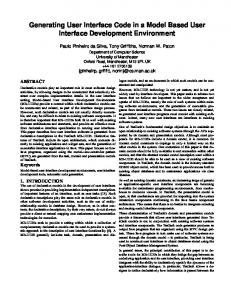
Fig. 1 depicts the main components of our UI and code generation architecture. The Model analyst agent uses the task-, database- knowledge bases and the database itself to analyze the task and domain models to derive sub-tasks, domain objects and their attributes; the user model is also loaded by the Model analyst agent. The Function analyst agent uses the Function description base to define the basic functions of the application. The loaded tasks have to be manually linked to the attributes of the domain objects and to the function defined by the system by the developer. From these linked objects, the UI creator agent automatically creates the user interface (UI) objects based on the mapping rules. Once the UI objects have been created, the code generator agent generates the code that will implement the user interface. Specially, our process does not only generate the user interface code, but also the application code behind needed to perform these predetermined tasks. The model analyst agent is used to load the task, user and domain models. In order to obtain the desired behavior of a database application task, the Function analyst agent defines the basic functions of an application by using the function
description base. These functions are, for instance, Display(), AddNew(), Update(), Delete(), Search() and Review() functions. Once the tasks in the task model have been linked to the attributes of the domain objects in the domain model, Concrete Interaction Objects (CIOs) are created based on the attributes characteristics and the relationships between the domain objects by the UI creator agent. These characteristics are for instance the data types, data length, is-key flag. Once the CIOs have been created, they are transformed into Final interaction Objects (FIOs). A FIO is described as a user interface control unit in a concrete platform. Finally, the code generator agent uses the Layoutknowledge base to generate the user interface code based on the FIOs and uses the Message base to generate the application code based on the defined functions. The application code is generated to perform the tasks linked to the functions which are defined by the Function analyst agent. Declarative models Data Model
Task Model User Model
Taskknowledge
Model analyst
Mapping rules
Database
UI creator
Databaseknowledge
Function analyst
Layoutknowledge
Messages
Code generator
Application code
User interface code
Function description
Fig.1. Main components of our UI and Code Generation Architecture.
In summary, the components of our UI and Code Generation Architecture are: The Database used to obtain the information on and of domain model. The Task-knowledge base that describes the rules of the task model. The Mapping rules base that describes the rules for specifying the concrete user interface from domain objects and the relationships between these objects and for transforming the concrete user interface to the final user interface. The Database-knowledge base that describes generic aspects of the database tasks, the advantages of the syntax and the structure of a query. The Layout-knowledge base that contains the syntactic design guidelines for controls, windows
and other widgets layouts. It also describes the semantic rules from which the control types are defined. The Messages base that contains the generic messages such as errors, warnings, information to users messages and so on The Function description base that describes the basic functions of a database application. For instance, in order to insert the data into a database it has to create a function Insert() which is used to get the data from end user and to input them into the database. Our process for generating the user interface is depicted in Fig. 2. The code generation process starts with loading the domain model from the database, the user model from a text file, the task model from a XML file. The system also defines the functions which are used to perform the generic database tasks such as the ones listed previously.
generated based on the domain model. Typically, these tasks are database manipulation tasks. The developer makes then the links between the specified tasks and attributes of the domain objects in the domain model and the links between the others tasks and the defined functions. The CIOs are created based on the linked objects; then these CIOs are transformed to FIOs. Finally, the user interface code and application code are automatically generated. In this process, we use the database, XML file and diagram file as resources to load the task, user and domain models. These resources are created by the business analyst/designer: The XML file stores the task model which is created by task model case tools such as ConcurTaskTreeEnvironment (CTTE) [11] or TERESA [12]. The Diagram file is used to describe the user’s characteristics. III.
As depicted in Fig. 2, the user interface generator has seven different steps. It starts with loading the task, user and domain models and ends with generating the user interface code and application code. These steps are discussed in detail in the following. The case study used in this paper is Translogistic, a project supported by the Walloon Region and labeled “competitiveness pole”. TransLogisTIC aims to develop a highly capable, competitive and complete combined transport as well as a high value quality logistics.
Database Loading models
Defining functions
Make links between tasks and methods
Creating concrete interaction object
Transforming CIOs to FIOs
Developer
Code generation workflow
Task model Domain model User model
Make links between tasks and attributes of domain object
Specifying database functions
Generating code
App code
UI GENERATOR
UI code
Fig. 2. Code generation workflow: UIs generated from task, user and domain models.
Once the models have been loaded, the developer determines the tasks from which the user interfaces can be
A. Loading the task, user and domain models The task model is loaded from a XML file; this XML file is built by the developer by using tools like CTTE [11] or Teresa [12]. The types of tasks, read from the XML file, are abstraction, interaction, application and user; these types are defined at the analyst level. At this level, the defined tasks represent different information including the unnecessaty information for the UI generation. For instance, the user task is a cognitive task that the end user selects a strategy to solve a problem or checks the result. Therefore, they are translated to action and operation types at the design level based on the following Task Mapping Rules (TMR): TMR1: Abstraction/Cooperation and application tasks are automatically mapped to action and operation tasks. TMR2: We do not consider user tasks since these are tasks from users and they do not communicate with the system. TMR3: Interaction tasks are not classified automatically but by the developer. Interaction tasks in ConcurTaskTrees are used to describe the enduser’s command to the system and end-user’s communication with system. In our process, the Exit task is an action task and Enter user name an operation task; however in ConcurTaskTrees, these same tasks are interaction tasks. This is indeed a limitation when choosing a task model built by the
ConcurTaskTrees Environment to generate a user interface (See for instance, EnterParameter and ProvideRequest tasks in Fig. 3). TMR4: All sub-tasks of a task mapped to an operation task from an interaction task are also mapped to operation tasks (See, for instance, task EnterParameter in Fig. 3). An Action task is a task used to describe the end-user command to the system such as close a dialog, delete a data record, search information, open a dialog and so on. An Operation task is a task which is used to describe the display of information to end-user or the reception of the information from the end-user. Tasks are mapped as follows : Task mapping Action task Abstraction task Interaction task Action or operation task Action task Cooperation task Operation task Application task User task None Fig. 3 depicts an example of the mapping between tasks in ConcurTaskTrees and in our process considering a typical AccessStudent Data task. Task Verify is not focused; tasks AccesstudentData, ShowResults are automatically mapped to action and operation tasks; tasks ProvideRequest, EnterParameters, SubmitRequest are mapped to action and operation tasks by the developer; tasks EnterName and EnterDepartment are automatically mapped to operation tasks since EnterParameters is mapped to an operation task.
AccesstudentData
Mapping
B. Defining the database application functions The system defines the functions for performing the generic tasks of a database application such as add new a record, delete a record, …. These functions are Display(), AddNew(), Update(), Delete(), Search() and Review() functions. They are described in detail in the Table 1: TABLE I.
Function Display() AddNew() Update() Delete() Search()
ShowResults ProvideRequest
EnterParameters
EnterName
(column attributes) and relationships between these objects. This database is determined by the developer. Based on the different databases, the different SQL queries are executed to obtain the information of the domain model. This information is stored specifically in the database data dictionary with respect to the DBMS type. For example, in Oracle, the table name is stored in the User_tables view; the column attributes are stored in the All_tab_cols view; the constraints are stored in the All_constraints view. All these are views of the Oracle Database data dictionary stored in the system user/schema. In SQL server, the table name is stored in information_schema.tables; the column’s attributes in the information_schema.columns; the constraints in the information_schema.constraints. They are, in this case, meta-system views owned by dbo, the database owner.
EnterDepartment
Review() SubmitRequest
DEFINED FUNTIONS
Description Used to select the data stored in the database and to displays this data to the user Used to insert a data record into the database Used to modify the data of an object in the database Used to delete the data records of an object in the database Used to filter the data records based on the some search condition which are determined by the user Used to review the data records by displaying the first, next, previous and last record
Action task Operation task
Fig. 3. Example of Mapping: an AccessStudentData task
The information in the user model is analyzed to classify the users into three different classes based on their ability to use the software. The analyzed information is the characteristics of the users such as the experience, skill, knowledge, behavior so on. The three classes of the user model are named “Simple”, “Mean” and “Complex” corresponding to three ability levels for using the software. Based on these user classes, the designer will design a complex, medium or simple user interface. Finally, the domain model is loaded from a concrete database by executing the SQL queries to obtain the information of the domain objects (table names), their attributes (column names), aspects of these attributes
C. Making links between tasks and domain’s objects The operation tasks are linked to the attributes of the domain objects (See Fig. 4) and the action tasks are linked to the defined functions (See Fig. 5). These links are defined by the developer based on the RLO rules. The Rules for making Link between Operation tasks and domain’s attributes (RLO) are given below: RLO1: Operation tasks that have at least one subtask are not linked to the attribute of the domain objects in the domain model. RLO2: Each leaf operation task (a leaf operation task is a task which has no sub-task) is linked to at least one attribute of the domain object. It means that all operation tasks are used to generate the user interface.
RLO3: One operation task can be linked to more than one attribute of the domain object. For example, task Name is linked to attributes First Name and Last Name. RLO4: One attribute of the domain object can be linked to more than one operation task. For example, attributes First_Name and Last_Names of object Transporters are linked to tasks Name and Manager.
Concrete Interaction Object Label: The label of the CIO; it will be used to label the control Control type: The control type which is used to communicate between the user and computer’s system Editable: Yes if this control can be edited by end-user; otherwise No
Display transporter
Display Transporter info
Manager Name
Email
Search Transporter
Return
Service name Type
Figure 4. Making the links between the operation tasks and the attributes of domain’s objects for the Translogistic Project
The Rules for making Links between Action tasks and defined functions (RLA) are: RLA1: At first, each action task is linked to a function which is defined by default and the name of the function is the name of the task. For example, the Task Search transporter is linked to the function Search (). RLA2: Each action task is linked to only one defined function. RLA3: Each defined function is linked to only one action task. RLA4: The original action task may be linked to a function and may be not based on the task goal. If this task starts by performing a function then the original action task is linked to this function. For example, when the task display transporter information starts, a display() function is performed so that its original goal is linked to function display().
Search Transporters
Choose transporter
ChooseTransporter()
Search transporter
Search ()
Display transporter info Return Name
Category
D. Creating CIOs A Concrete Interaction Object (CIO) is a graphical object for entering and displaying the data that the user can see, feel and manipulate [15]. A CIO is synonymous to a control, a physical interactor, a widget or a presentation object such as text-field, combo-box, check-box, button … A CIO in our process is defined by its label, control type, editable attributes as follows:
Address
Exit()
Fig. 5. Making the links between the action tasks and the defined methods for the Translogistic Project
The concrete user interface should define some, but not all, aspects of the final presentation. This ensures sufficient flexibility in being able to realize the presentation on a variety of devices and platforms. Application developers should be able to define themes and other policies for guiding the transformation for a particular device/platform. For example, the application can define the type and size of font … In order to determine the attributes of a CIO we need to specify the domain object (called edited object) on which the data can be changed and to specify the main attribute of the domain objects (called main attribute). An Edited object is an object determined by the developer. One can add a new data into, get data from, search data on, … an Edited object if a task is linked to basic functions New(), Delete(), Search() … A Main attribute of a domain object which relates to an Edited object through a 1-1 or n-1 relationship is an attribute determined by the developer. A Main attribute is used to determine the control type in the next step. For each leaf task, a CIO is created. Each CIO is created based on the name of the task, the characteristics of the domain attributes which are linked to this task and the relationships between the domain objects. These characteristics are the data type, length, is-key flag and so on. The name of the CIO is the name of the linked task; the control type and editable attributes of the CIO are determined based on the RDC mapping rules presented below. Fig. 6 depicts how to create the CIOs based on the links between the tasks and the domain objects, and the defined functions. In the example, the object Transporters is an edited object, the attributes Service name and Service_Name are the main attributes. One task can be linked to more than one attribute of the domain objects and one task has one determined data type. Therefore if a task is linked to more than one attributes and if the data type of these attributes is T then its data type is T. Otherwise the data type is text. For example, if a Task Total is linked to columns Price and Amount and the data type of both columns is number, the data type of the CIO is number. But if a task Make Appointment is linked to columns Date (datetime type) and Address (text type) then the data type of CIO is text. And if a task is linked to a function then its data type is Void. In order to simplify determining the control type we need to specify the class to which the linked
attributes belong. If the linked attributes derive from more than one object and if the relationship between the edited object and another one (called A) is 1-1 or n-1 then these attributes belong to the edited object group; if it is 1-n or n-n then these attributes belong to class A. Display transporter
Display transporter info Name
Display appointments
Note
Addres
Note Table NotEditable
Time
Name Text field Editable
Time Table NotEditable
…
Search Service info
Search Button Editable
Close Button Editable
Search() Service name Service name Compobox Editable
Exit()
Type
example, in Fig. 6 the CIOs Note, Address and Time derive from object Appointments. RDC5: If the CIOs of the table type belong to the same CIO class then they are assigned to the same table control. Each CIO of type table in our process is a separate interface, but in practice it is just a column of a table. For example, the control type of the CIOs Note, Address and Time is the table type and they are separate CIOs but belonging to the same group Appointments; they are then assigned to the object Appointments. RDC6: If the data type is the container type then the control type of the task is Tab or Panel control. These rules are summarized in Table 2:
Type Number field NotEditable
Address Table NotEditable
Fig. 6. Creating concrete interface object based on the Translogistic Project
The control type of a CIO is determined based on the following Rules for Determining the Control type. RDC1: When a task derives from the attributes of the edited object then the control type of the CIO created for this task is Text field or Text box if the data type is Text; Number field if the data type is Number; Check box/Radio if the data type is Boolean; Date picker if the data type is Date and the Editable attribute value of this CIO is Yes. For example, in Fig. 6 the CIOs Name, Email, Telephone … derive from the object Transporteurs. RDC2: When a task derives from an attribute of a domain object which is not the edited object and if this attribute is not the main attribute and the relationships between the edited object and another one is ‘1-1’ or ‘n-1’ then the control type of the CIO is Text field or Text box if the data type is Text; Number field if the data type is Number; Check box/Radio if the data is Boolean; Date picker if the data type is Date and the Editable value of this CIO is No. RDC3: When a task derives from an attribute of the domain object that is not the edited object and if this attribute is the main attribute and the relationships between the edited object and another one is ‘1-1’ or ‘n-1’ then the control type of the CIO is Combo box and the Editable attribute value of this CIO is Yes. For example, in Fig. 6, the CIOs Service name derives from the object Services. RDC4: If a task derives from the attribute of a domain object which is not the edited object and the relationships between the edited object and another one is ‘1-n’ or ‘n-n’ then the control type of the CIO is table and the Editable value of this CIO is No. For
TABLE II. Data type of attribute of domain’s object
CIO’S CONTROL TYPE
CIO created derives from following components Relationship Related between edited Edite Main object object - related d attrib object object ute 1-1 1-n n-1 n-n
(CIO) Control type
Text
Text field
Text (length>500) Text
Text box
Text (length>500) Text
Text box
Text
Table
Number
Number field
Number
Number field
Number
Combo box
Number
Table
Date DateTime Date DateTime Date DateTime Date DateTime
Date picker
Boolean
Boolean
Check box Radio button Check box Radio button Check box Radio button Table
Container
Tab
Container
panel
Void
Button
Void
Menu
Void
Pop-up menu
Boolean Boolean
Text field
Combo box
Date picker Combo box Table
Edita ble
Based on the classes in the user model, the system selects a correct control type among the possible control types. In other words, if there is more than one control type determined for one CIO then our software chooses one of them for this CIO from the classes in the user model. For example the control type of the CIO Exit can be Button, Menu or pop-up menu types. If it is “Simple” or “Mean” then the control type is Button; if it is “Complex” then the control type is Menu. E. Translating CIOs to FIOs The Final Interface Object (FIO) represents the operational interface object that is running on a special computing platform either by interpretation (e.g., through a web browser) or by execution. The FIO is determined based on the CIO in a certain language, on a certain platform and so on. A Final Interaction Object is defined as follows: Final Interaction Object Label: The label of the control Control type: The control type is specified in certain platform Editable: Yes if this control can be edited by end-user; otherwise No Position: The position (X, Y) of control in a form or in the screen Size: The dimension of the control, it contains width and height
The FIOs are specified based on the CIOs created in Section D and the programming language determined by the developer. For each CIO, a correlative concrete control is created. As discussed, a CIO is defined by the attributes Name, control type, editable, position and size. These attributes are created as follows: The Label of the FIO is the Label of the CIO The Control type of the FIO is determined based on Table III for the Java and VB.Net languages. The value of the FIO’s Editable is the value of the CIO’s Editable. The Position and size attributes of a FIO are determined based on the order of creating the FIO and the length characteristic. Table III shows the control type mapping for Java and VB.Net . TABLE III. Control type of CUI Text field Text box Number field Combo box Date picker Check box Radio control Table Container Tab Panel
Java-AWT TextField TextArea
Checkbox Choice Table Container Panel
FIOS’ CONTROL TYPE
Control type in Java-SWING VB.Net JTextField TextBox JTextBox TextBox NumTextBox JComboBox ComboBox DateTimePicker JCheckBox CheckBox JRadioButton RadioButton JTable DataTable JContainer ContainerControl JTabbedPane TabPage JPanel Panel
Button Menu Pop-up menu Label List Dialog
Button Menu PopupMenu Label List Dialog
JButton JMenu JPopupMenu JLabel JList JDialog
Button Menu PopupMenu Label ListBox Dialog
F. Performing the defined functions In order to perform the functions linked to the tasks in the previous steps, our software determines the controls which are affected by performing these functions. These functions have been defined in Table I. After determining the control, the software specifies how the control is affected. For example, it has to get data from these controls or to display data on these controls. Based on the goal of each function the software generates the different SQL queries such as Select/Insert/Update/Delete. These SQL queries are built based on the attributes of the domain objects linked to the tasks. G. Generating code Finally, the user interface and application code are automatically generated based on the FIOs, the functions linked to the tasks and the concrete programming language. Different code syntaxes are generated for the different languages. Some important points need to be considered when generating the code: The code syntax is generated differently considering the languages. The code generated should be identified, clear and easy to understand which is crucial to maintain, enhance and develop this code. The control name is unique so we have to find a solution for naming a control automatically so that the generated name relates to the CUI name and is unique too. Creating the name must be uniform and standardized since we need to use these names when we generate the code to display and update data. The controls are created in a concrete language based on the attributes of the CUIs; the control type is determined by the Control type of the CUIs; this control is named by the name of the CUIs, etc. IV CONCLUSIONS To be efficient, data-intensive systems that are an important component of today’s software applications need effective human-computer interaction. User interfaces for such data systems has been a recurrent research issue and nowadays these UI have to support automatic generation to adequately be dealt with. We have proposed here a framework whose purpose is to drive the automatic database user interface design and code behind generation from the task, user and domain model combined together. Section 2 has presented our automatic UI and code generation process taken together the task, user and domain models. Section 3 has explained our UI generator.
This framework has aimed at offering a low cost, short time-to-implementation and efficient development environment from the business user side. Indeed, the objective is not to provide a tool for supporting the development of the database applications to not only the developers but also to support non-IT end-user. We have applied the research on Translogistic, a project supported by the Walloon Region that aims to develop a highly capable, competitive and complete combined transport as well as a high value quality logistics is used as a case study ACKNOWLEDGMENT Most of the research on outbound logistics made at UCL/CESCM and the contents of this paper have been initiated by the Walloon region under the auspices of the TransLogisTIC project (www.translogistic.be). We gratefully acknowledge the Region and the project industrial partners for their support. REFERENCES [1]
C. Pribeanu. “An Approach to Task Modeling for User Interface Design”. Proceedings of World Academy of Science, Engineering and Technology, Vol.5, April 2005 [2] P.P. Da Silva, T. Griffiths, N. Paton, “Generating user interface code in a model based user interface development environment”. In Proc. of Advanced Visual Interfaces (AVI'00), New York, pp. 155–160, 2000. [3] E. Schlungbaum and T. Elwert, “Automatic user interface generation from declarative models”. In: J. Vanderdonckt, Ed, Proceedings of Computer Aided Design of User Interfaces (CADUI'96), pp. 3–18, 1996. [4] B. Myers , S. E. Hudson , R. Pausch, “Past, present, and future of user interface software tools”, ACM Transactions on ComputerHuman Interaction (TOCHI), v.7 n.1, p.3-28, March 2000 [5] L. Moroney and M. MacDonald, “ASP.NET Applications in Pro ASP.NET 1.1” in VB .NET From Professional to Expert, Apress, pp. 183- 230, 2006 [6] T. Griths, P. Barclay, J. McKirdy, N. Paton, P. Gray, J. Kennedy, R. Cooper, C. Goble, A. West, and M. Smyth. “Teallach: A Model-Based User Interface Development Environment for Object Databases”. In Proc. of UIDIS'99, pp. 86-96, Edinburgh, UK, September 1999. [7] J. Eisenstein , A. Puerta, “Adaptation in automated user-interface design”, Proceedings of the 5th international conference on Intelligent user interfaces, p.74-81, January 09-12, 2000, New Orleans, Louisiana, 2000. [8] C. Pribeanu. An Approach to Task Modeling for User Interface Design. Proceedings of World Academy of Science, Engineering and Technology, Vol.5, April 2005. [9] P. Pinheiro da Silva. “User Interface Declarative Models and Development Environments: A Survey”. In Proceedings of DSVIS2000, volume 1946 of LNCS, pages 207-226, Limerick, Ireland, June 2000. Springer-Verlag. [10] A. Mahfoudhi, M. Abed, M. Abid. “Towards a User Interface Generation Approach Based on Object Oriented Design and Task Model”. TAMODIA'2005 : 4th International Workshop on TAsk MOdels and DIAgrams for user interface design For Work and Beyond Gdansk, Poland September 26-27, 2005. [11] F. Paternò, G. Mori, and R. Galiberti, “CTTE: an environment for analysis and development of task models of cooperative applications”. In CHI ’01 Extended Abstracts on Human Factors in Computer Systems. Seattle, Mar., ACM Press, 21–22, 2001. [12] F. Paternò, C. Santoro: “One Model, Many Interfaces”. Proc. of CADUI'2002, Kluwer. pp.143-154, 2002
[13] C. Pribeanu. “Tool Support for Handling Mapping Rules from Domain to Task Models”. Coninx, K., Luyten, K., Schneider, K. (Eds.): Proc. of TAMODIA 2006, Hasselt, Belgium, 23 – 24 October. Lecture Notes in Computer Science - LNCS 4385, Springer 2007, pp. 16-23. [14] M. Elkoutbi, I. Khriss, and R. K. Keller, “Generating User Interface Prototypes from Scenarios”, in Proceedings of the Fourth IEEE International Symposium on Requirements Engineering (RE'99), pages 150-158, Limerick, Ireland, June 1999. [15] D.A. Duce, M.R. Gones, F.R.A. Hopgood, J.R. Lee (Eds.), “User Interface Management and Design”, Proceedings of the Workshop on User Interface Management Systems and Environments, Lisbon, 4-6 June 1990. [16] J. Nichols, A. Faulring. “Automatic Interface Generation and Future User Interface Tools”. In: CHI. Proceedings of the Workshop on the Future of User Interface Design Tools, 2005 [17] K. Gajos and D. S. Weld. “Supple: automatically generating user interfaces”. In IUI’04, Funchal, Madeira, Portugal, 2004. ACM Press. [18] A.M. Rosado da Cruz, J.Pascoal de Faria. “Automatic Generation of User Interfaces from Domain and Use Case Models”. Quality of Information and Communications Technology, 2007. QUATIC 2007. 6th International Conference on the.