From mockups to user interface models: An extensible model driven approach José Matías Rivero1,2, Gustavo Rossi1,2 , Julián Grigera1, Juan Burella2,3, Esteban Robles Luna1,2 1
LIFIA, Facultad de Informática, UNLP, La Plata, Argentina {mrivero, gustavo, julian.grigera, esteban.robles}@lifia.info.unlp.edu.ar 2 Also at Conicet 3 Departamento de Computación, Universidad de Buenos Aires
[email protected]
Abstract. Sketching web applications with mockup tools is a common practice that improves the process of elicitation and validation of requirements in web applications. However, mockups are used as a “quick and dirty” way of gathering requirements thus discarded before development. As a consequence, concepts captured in them are usually lost in the manual transformation between mockups and the final user interface. In this paper we present a model-driven approach that overcomes this problem by importing mockups and then transforming them into a technology-dependent model. Development then begins from the imported version of the mockups.
1 Introduction Agile methods are appealing for Web applications because they help to provide quick feedback to customers, following short development iterations and involving them in the development endeavor. Being requirement elicitation and managing an important aspect of Web application development, most mature model driven web engineering approaches (MDWE) use informal textual descriptions (e.g. Use case or User story) to capture them. However, some requirements are not clearly understood and depend on the interpretation of the observer. Particularly, requirements related to interface and interaction issues that are paramount in Web applications are usually remain unchecked until the application has been partially developed. Mockups have become a very popular artifact to capture requirements in agile methods. A mockup is a sketch of a possible user interface (UI) of the application that helps to agree on broad aspects of the UI and can be easily created by any stakeholder. In the last years, its use has been quickly expanded, generating a myriad of tools such as Axure [1], Pencil [2] or Balsamiq [3] that help to create and administrate mockups. Plain HTML can be also used to provide more detailed and realistic UIs. However, most development approaches use them informally and consequently as a “quick and dirty” way of gathering requirements, not providing ways to reuse them in the development process. In this paper we present a model-driven approach for reusing mockups, engaging them as part of either a MDWE process or even in a more handcrafted coding based
approach. We first show how mockups can be created by using any of the aforementioned tools and then imported as instances of a metamodel. Then, we show how to transform these instances to produce either models or technology dependent code that can be used during the development process. Also, as part of our technology dependent transformations, we show how UI structure is separated from UI behavior to allow seamless evolution along the development cycles. In summary, the contributions of this paper are the following: We present a metamodel that abstracts a common set of mockups models and show how we can import mockup model instances. We show how instances of the mockup metamodel can be translated to different technology dependent concrete interface models. We show that the approach is easily extensible to other mockup tools and UI technologies. Finally, we show how we handle evolution in our approach. The rest of the paper is structured as follows: in Sect. 2 we present some related work. In Sect. 3 we present our approach in detail. In Sect. 4, we show how we handle evolution and in Sect. 5 we show some implementation details. In Sect. 6 we show how we can easily extend the approach to use different mockup tools and new technology dependent transformations. Finally in Sect. 7 we conclude and present some future work we are pursuing.
2 Related work Several successful experiences with UI mockups in the context of agile development processes in industry have been reported in the literature. In [4, 5], the use of UI prototypes in conjunction with User stories in real projects was considered a key factor in the entire development process, and facilitated interaction with stakeholders and between different work teams with distinct roles. A similar approach is described in [6], where user interface mockups resulted useful for interaction between analysts, developers and customers in companion with summarized User stories. At the same time many model-driven approaches to user interface specification have been proposed; in most of them UI definition starts by specifying domain objects or concepts like tasks or classes [7], thus neglecting the early capture of aspects like presentation and look and feel that are essential for customers and final users. In [8], a MDA-compliant model-driven UI environment has been defined in order to cope with the complexities of defining modern user interfaces. The approach presented in the paper consists in a framework allowing multi-context UI definition starting from a model belonging to one of four levels of abstraction, from task and concepts to final interface specification in a concrete technology. Once defined the model in a concrete level of abstraction, the framework facilitates transformations to any other level of abstraction, including the less abstract of all: the Final UI (FUI) implementation. Also, transformations between models at different contexts of use like, for example, desktop or Pocket PCs, are provided. In the context of the paper, the approach presented in our work depicts a transformation path from mockups to an abstract mockup model similar to a Concrete UI (CUI), and then reification (a decreasing abstraction transformation) to a Final UI (FUI) for supported technologies. We have tested and analyzed several mockup UI tools such as Axure, Pencil, GUI Design Studio [9] and Balsamiq to define our UI mockup metamodel concepts. De-
spite some of these tools provide interaction or behavior specification, the metamodel proposed in this paper only tackles structural UI aspects, in order to support the vast majority of mockup tools.
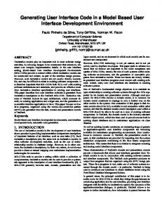
3 Our approach in a nutshell To give a context of our approach we will show how we can use it in WebTDD [10], though it can be also used with other development styles such as a RUP based process [11] or even with Extreme Programming [12]. Nevertheless, with some additions and enhancements like those commented in Sect. 7, we are pursuing a better development tasks automation and assistance. In WebTDD, requirements are captured using mockups and WebSpec [13]. The approach presented in this paper crosscuts two important steps of the WebTDD process: Requirements gathering and Implementation (UI derivation) (Fig. 1).
Fig. 1. Our approach’s process
During the requirements gathering steps, the approach is used to import mockups and derive them to a concrete technology so that customers can check on a preliminary version of the application’s interface. During the development phase, the UI of each requirement can be implemented from the “derived” version of the mockups, overcoming the translation problem between mockup and implementation. The approach proposed in this paper detailed in Fig. 2, consists in using a metamodel that helps to abstract mockups in a tool-independent way. A collection of mockup parsers (1) are provided for each tool, allowing a concrete mockup conversion from each one into our metamodel. When the mockup parsing ends, a post-processing is performed (2) to rearrange the parsed UI controls and the final abstract mockup model is obtained. Once the whole importing process finishes and the complete abstract mockup model is instantiated (3), it can be used to derive stub UI classes/models implemented with concrete technology (4) - similar to what is provided by tools like Axure. For each concrete technology of interest, a code generator can be constructed to transform mockup models to concrete UIs able to run in a browser. This code generator will choose the more appropriate widgets in the particular web technology to implement the respective UI components present in the abstract mockup, deriving the code that constructs and configures each one.
Fig. 2. Our approach in action
3.1 Importing mockups The mockup importing process starts with individual UI component detection and parsing from a mockup file created with a specific tool (Fig. 2, step 1). Since most of mockup tools make focus in user interface sketching, unlike common UI frameworks or technologies they don’t provide ways of defining natural UI control composition. Nevertheless, our metamodel contemplate this kind of composition in order to derive complete UI specifications for concrete technologies. Thus, mockup parsers must instantiate metamodel components with an initial composition structure. Taking into account this requirement, a mockup parser for a concrete tool must scan a mockup file composed with the tool and return a collection of metamodel controls representations grouped in “clusters”. Each “cluster” represents a set of components in a unique graphic space (for example, a page, a window or another UI control grouping concept that a mockup tool could define). For each control, a common set of properties are read (e.g., position coordinates and sizes) and a specific subset of properties are obtained from the source file for specific types of controls (for example, text content in labels or URL in links). Once the UI control groups are obtained, a post-processing over each particular group is performed. The first processing task performs hierarchies detection: if a UI control is graphically inside another and the first one is a composite control, the second one is added as a child of the first. Finally, the controls are grouped in Pages. At this phase, a UI model is composed of a set of pages containing a hierarchyarranged collection of controls each one. Because of the myriad of different Web UI technologies implementations, an absolute positioning scheme is not sufficient to model a user interface in a platform-independent way. To avoid this problem, the components are arranged into a specific platform-independent layout used later to derive positioning information in the code generation phase. Actually, we developed an inference layout algorithm to arrange the UI controls into a GridBagLayout (described in Sect. 6), the most expressive and extensible layout that the metamodel supports at the moment. After this last post-processing task, the complete UI specification model with a platform-independent layout configuration is obtained. This abstract and formal UI description can be used later for UI platform-specific specifications derivation.
3.2 Automatic UI model derivation Models obtained in the parsing phase can be derived to different concrete implementations using the previously mentioned code generators. The derivation process consists in iterating through each model element in a Visitor-like process [14] and generating an intermediate representation of the UI. This representation is used to derive the final UI code that will become part of the web application from the original abstract mockup model. The derivation also considers the generation of code that assigns a unique identifier to every UI component being constructed in the concrete technology. This feature is fundamental in order to reference user interface controls from manually written code that implements the UI behavior or enhance the derived components features. Finally, code generators derive the initial structure of code files that can be used to enrich generated UI components or add behavior. The separation of derived source code that captures the representation of the mockup in the concrete technology and the manually written source code is paramount to isolate UI interaction or detailed specification from automatically generated user interface code and structure.
4 Evolution We introduced our approach as useful in the context of agile methodologies, because mockups are commonly used as a requirements gathering tool. Since agile processes are characterized as iterative, with short development cycles and continuous interaction with final users and stakeholders, changes in the UI specification are common, resulting in a great number of user interface iterations through the complete development process. Thus, the evolution of the UI is an important concern to be considered in our approach. An extremely simple example of this problem can be observed in Fig. 3. The Balsamiq mockup shows a first version of a login screen that has a simple change to fulfill a new stakeholder requirement.
Fig. 3. A UI mockup change example
The possibility of enriching the generated mockup implementations without modifying the generated source code, allows a clear separation between UI presentation and behavioral concerns. Consequently, if the structural UI definition doesn’t change, modifications to be made in behavioral aspects as a result of the application’s natural evolution can be done isolated, therefore simplifying evolution. Structural changes in UI mockups present a more complex problem, because modifications in the user interface structure could cause invalid or obsolete references to components that have changed or have been deleted in a new iteration. Thus, a more sophisticated way of relating static aspects of an UI derived from source mockup files
and dynamic aspects added with manual coding, is required. In the presented example, a change in the UI is proposed where a button is deleted and a link is added. This modification implies that the behavior code referencing the deleted “Return” button is no longer valid in the new version of the UI and consequently should be removed or changed. Additionally, since all the behavior code is maintained, actions associated to the new added link should be coded manually. In order to solve this problem, an indirect way of referencing UI components during the implementation is proposed. The solution we propose consists in the construction of an identifier translation function to associate natural name identifiers for UI components to native ids assigned by the code generators; we call this function a reference translator. This approach has two advantages. First, the implementation code references UI controls through natural identifiers as in pure manually coded Web applications. Besides, if in some future iteration an existing component identifier assigned by the code generator changes, a simple tuning in the reference translator is sufficient to solve the reference problem. Changing a mockup source file could imply one of three possible actions from an individual UI component point of view: (1) a new UI control is created, (2) an existing UI control is preserved and possibly modified or (3) an existing UI control is deleted in the new iteration. The first one presents no complexity since it doesn’t invalidates any behavior implemented in code. The second could entail a reference problem if the automatically generated UI component identifier changes from the previous iteration. In this case, a correction to the reference translator solves the problem. Finally, the last case implies behavioral changes and, therefore, the manually written source code should be changed to reflect the interaction semantics of the new UI. Because of the non-predictable nature of UI control id generation, the best solution is to redefine the reference translator after each iteration. Fig. 4 shows how a UI change like the one expressed in the example of Fig. 3 can be handled with preservation of manually added behavioral code using the reference translator approach.
Fig. 4. Code preservation through mockup UI evolution using a reference translator
In the context of the MDD architecture vocabulary [15], the commented reference translator could be considered as part of a domain framework for a concrete implementation platform. All access to the UI structure should be done using the provided framework in order to write portable code between iterations.
So far, the presented approach solves the reference consistency problems between automatically generated UI and manually coded behavior when new UI components are added or existing ones are modified between iterations. However, the control deletion is still a problem, since some of the controls referenced in the code written by hand could no longer exist in the new UI version. Due to the potentially complex logic implemented in behavior code, it is very difficult to apply an automatic and safe refactoring that removes all the operations implied by a deleted control. Nevertheless, the problem can be solved in a test-driven way. When the first UI iteration is generated, a test is written to check that the structural requirements are satisfied. When a mockup is changed and a new UI version is obtained, the user interface structure test is run after the respective changes were done in the reference translator. If the test fails, the handwritten code should be changed to fit the new UI structure. On the other hand, if the test passes, it shows that the current handcrafted code will work with the new user interface structure, but its semantic could be obsolete or invalid. In both cases, the test should be updated in order to assert the new UI structure features. An outline of the UI iteration life cycle can be observed in Fig. 5.
Fig. 5. UI life cycle
In conclusion, in handcrafted code approaches, on the first UI iteration, three artifacts are derived from abstract mockups specified with our metamodel: the user interface structure, a first version of the reference translator and an initial code behavior structure. To obtain the first functional UI version, the initial behavior must be written after assigning natural ids to those automatically generated in the reference translator. Also, user interface structural test writing in this phase is encouraged in order to reflect the initial UI structure requirements. After each iteration, the UI structure and reference translator are regenerated, but the behavior code and structural test are maintained and should be updated accordingly. Assuming that the mockup tool assigns and maintains a unique id for each widget in the mockup (as Balsamiq does), it can be stored in metamodel UI components (as is shown in Sect. 5). Once stored, this id can be used to trace changes made between mockup iterations through metamodel instances comparison, thus facilitating or even avoiding some of the manual steps commented later (e.g, writing and executing manual UI integrity tests in order to detect widget deletion). Each change detected between mockup versions can be translated to the derived implementation (automatically through refactorings, when possible).
5 Implementation In Fig. 6, the structure of the proposed metamodel derived by finding and abstracting common features between the set of analyzed tools is denoted. An abstract mockup model has a root object which is an instance of the MockupModel class. A MockupModel is composed by one or more pages (Page instances), which in turn contain a collection of UIControls, each one representing a UI mockup component. An UI control has position and size information and can belong to one of two classes: CompositeControl and SimpleControl. The first ones work as a container of another UIControls, while the second ones are atomic UI components like buttons, links and textboxes. The set of UI controls types included in the metamodel are those present in all the observed mockup tools.
Fig. 6. The core mockup metamodel
Additionally, the metamodel considers different layouts that can be associated to any composite control (including Pages) to arrange its inner UI controls. As shown in the figure, the layout is a separated concern and does not mix with the UI definition. We modeled three different kinds of layout, inspired in some LayoutManagers present in Swing [16]: FlowLayout, BoxLayout and GridBagLayout. A FlowLayout does not sort the UI controls in any particular way, but simply puts one after another in an arbitrary manner. A BoxLayout aligns UI controls in a vertical or horizontal sequence. Finally, a GridBagLayout arranges components in an HTML table-like way: each UI control is placed in a particular row and column of a grid, and is extended for a concrete numbers of columns and rows right and down respectively. As said before, this layout was the one chosen to be used as default because of its richness and flexibility, and an iterative algorithm is applied over the parsed widgets in order to configure it. This algorithm starts with a GridBagLayout with 1 row and 1 column, and tries to put the components in a particular cell depending on its relative position in its parent widget. If more than one component is assigned to a cell, a row or a column is added and the process starts again. To choose between adding a new row or a new column, the algorithm detects in which direction the colliding components are closer, and chooses the option that promotes better widget isolation. A graphically representation of the process execution can be appreciated in Fig. 7. Similar algorithms can be applied to infer another layouts like, for example, BoxLayouts.
Fig. 7. GridBagLayout inference algorithm execution
We claim that the proposed metamodel is sufficient to specify the structural composition of a large set of common UIs. Likewise, with the addition of layout-oriented composite widgets supported by existing mockup tools like tab or accordion panels, an even wider set of UI could be expressed. To preserve generality, the metamodel limits the existing UI widgets to those which are commonly present in most popular mockup tools and avoids the specification of advanced aspects like behavior or interaction. Since only static aspects of an UI are considered, it is important to allow the derived models to be extended in several ways. As has been said, the generated implementation assigns an id to every derived UI control that can be used to obtain a reference to the component in runtime and manipulate it, for example, attaching event listeners to add interaction to the mockup. Besides, for each data-oriented control like Lists or Tables, an empty data source, that can be refined to provide real data to the functional UI, is generated. Finally, if some features of one or more user interface components in a concrete technology only can be specified at construction time, the domain framework provided allows defining them manually in a separated source code file. Then, when the user interface control is constructed by derived code, the extra parameters are added implicitly to the component’s constructor call without having to modify the generated mockup source code file. As a proof of concept, we successfully developed mockup model parsers for the mockup tools Pencil, GUI Design Studio and Balsamiq, and constructed code generators for YUI [17] and Ext JS [18] Web technologies. In the context of MDWE approaches, we are implementing transformations to convert instances of our metamodel to UsiXML Concrete UI (CUI) models [8] and WebRatio templates [19]. With this addition, the model-driven approach presented in this paper can be linked to other MDWE and model-driven UI methodologies and thus be combined with them.
6 Framework extensibility In the following subsections we show how we can extend our approach with a new mockup tool and a new derivation to a technology dependent framework. Once defined a mockup parser for a new mockup tool or a code generator for a new concrete technology, it can be easily plugged in our framework.
6.1 Adding new mockup tools Adding support for a new tool in the approach consists in implementing an interface that receives a mockup source (e.g. a file) and returns a collection of controls separated in independent graphically spaces or “clusters”. All the subsequent postprocessing is performed with existing software components, thus allowing the reuse of all the mentioned tasks for any new parser that could be defined in the future. In Fig. 8.a we show a class diagram of a mockup translator structure. A MockupTranslator is the class responsible of taking a concrete mockup source (the generic type TSource, usually a File) and translating it into an instance of our metamodel (MockupMetamodel). An instance of a MockupTranslator is configured with a concrete ControlParser, which implements the UI control parsing and grouping for a concrete mockup tool. Additionally, an instance of ControlParser is configured with a concrete MockupMetamodelFactory, which provides methods for constructing metamodel elements for a particular representation of our metamodel (e.g., a memory-stored one).
Fig. 8.a. Mockup translator structure
Fig. 8.b. Code generator structure
The fact that the architecture expects from the mockup parsers only individual control parsing and spatial grouping, implies a few assumptions in the features of the source mockup format and, consequently, in the mockup tool used to construct it. Hence, a mockup tool capable of drawing variable-size UI components and supporting the set of user interface elements included in the metamodel is sufficient to compose a complete mockup translatable to our metamodel. 6.2 Adding new technology derivations Extending the derivation scheme to add support for a different Web technology requires the implementation of an interface that receives an instance of our metamodel and derives a collection of specifications which will be translated later by our framework into specific implementation artifacts as mentioned before. The framework implements an extensible code generation library that resolves some usual code generation concerns like indentation and files creation and also provides an OO way of defining and composing generated code artifacts. The idea behind the construction and use of that library was having a pure object-oriented approach to define and compose textual representations generation with total freedom to compute and transform metamodel instances returned by mockup parsers. The structure of a common code generator using our framework can be observed in Fig. 8.b. Any code generator defined must implement the MockupCodeGenerator
interface in order to be plugged into our framework. The CodeArtifact class is defined by the code generation library and generalizes and abstracts some aspects relative to the generation of textual code artifacts. Additionally, the interface MockupMetamodelVisitor defines methods that must be implemented in order to apply the Visitor design pattern for code generation, and thus its implementation is encouraged. Adding support for MDWE and model-driven UI approaches implies the definition of code generators for deriving textual model representations as those generated by MDD tools to serialize models into files. The derived model could be later imported in the respective model-driven tool and thus can be used in the context of its associated MDD methodology.
7 Concluding Remarks and Further Work In this paper we outlined a model-driven approach to represent UI mockups allowing to import them from existing sketching tools and generating code for different modern Web technologies. The implemented software allows translation from mockups constructed with any of the mockup tools supported to any Web technologies, using our mockup abstract model representation as a “pivot”. The architecture of the framework constructed implies a small amount of work to add support for new mockup tools or Web technologies. Additionally, we show how the derived code for Web technologies can be enhanced to obtain final implementations and handle application evolution, allowing mockups being a reusable software specification artifact. Finally, the automatic model-to-code translation promotes a uniform UI design style, avoids common manual coding errors [20] in UI implementation and problems related to presentation discrepancies between browsers in web applications. The construction of a tool that facilitates the introduction of refinements to the parsed UI models (e.g. widget composition) and also captures changes made in metamodel instances in order to apply refactorings and changes necessary to reflect them in the underlying implementation represents a potential future work. More detailed UI specifications surely should be needed in real world cases as can be seen, for example, observing modern interaction patterns and UI widgets in Web applications [21]. Adding support for more mockup tools, Web technologies, MDWE and model-driven UI methodologies represents a fruitful field for future work. We continue working in mockup tools and Web technologies analysis in order to define new mockup parsers and code generators. Also, UsiXML CUI models and WebRatio templates generators and parsers are being improved in order to fully support transformations. Finally, linking our UI metamodel with others metamodels oriented to domain, behavior, data transformation and process workflow definition could enhance model instances semantics, resulting in more code artifacts able to be automatically generated. However, while these semantic increments could provide a more MDA-based process, how to link the derived code with code-based agile methodologies remains being a challenge and represents some important future work we are pursuing.
References 1. 2.
Axure, http://www.axure.com Pencil, http://www.evolus.vn/pencil
3. 4.
Balsamiq, http://www.balsamiq.com Ferreira J., Noble J., Biddle R.: Agile Development Iterations and UI Design. In: Agile
2007, pp. 50–58. IEEE Computer Society, Los Alamitos (2007) 5. 6. 7. 8. 9. 10. 11. 12. 13. 14. 15. 16. 17. 18. 19.
20.
21.
Noble J., Biddle, R., Martin, A.: The XP Customer Role in Practice: Three Studies. Agile Development Conference (ADC'04), pp.42-54. (2004) Ton, H.: A Strategy for Balancing Business Value and Story Size. In: Agile 2007 Conference, pp. 279-284. IEEE Computer Society, Washington, DC (2007) Lu, X., Wan, J.: Model Driven Development of Complex User Interface. In: the MoDELS 2007 Workshop on Model Driven Development of Advanced User Interfaces. CEUR-WS. (2007) Vanderdonckt, J.: A MDA-Compliant Environment for Developing User Interfaces of Information Systems. In: Pastor, O., Falcão e Cunha, J. (eds.) Advanced Information Systems Engineering. LNCS, vol. 3520, pp. 16-31, Springer, Heidelberg (2005) GUI Design Studio, http://www.carettasoftware.com/guidesignstudio/ Robles Luna E., Grigera J., Rossi, G.: Bridging Test and Model-Driven Approaches in Web Engineering. In: Gaedke, M., Grossniklaus, M. (eds.) Web Engineering. LNCS, vol. 5648, pp. 136-150. Springer Verlag (2009) Kruchten, P.: The Rational Unified Process: an Introduction. Addison-Wesley Longman Publishing Co., Inc. (2003) Beck, K.: Extreme programming explained: embrace change. Addison-Wesley. (2000) Robles Luna, E., Garrigós, I., Grigera, J., Winckler, M.: Capture and Evolution of Web requirements using WebSpec. To be published In: the 10th International Conference on Web Engineering. (2010) Gamma, E., Helm, R., Johnson, R., Vlissides, J.: Design Patterns: Elements of Reusable Object-Oriented Software. Addison-Wesley Professional. (1994) Tolvanen, J., Kelly, S.: Domain Specific Modeling: Enabling full code generation. WileyIEEE. (2008) Using Layout Managers – The java Tutorials, http://java.sun.com/docs/books/tutorial/uiswing/layout/using.html YUI Library, http://developer.yahoo.com/yui/ Ext JS – Javascript Framework and RIA Platform, http://www.extjs.com/ Acerbis, R., Bongio, A., Butti, S., Ceri, S., Ciapessoni, F., Conserva, C., Fraternali, P., Toffetti Carughi G: WebRatio, an Innovative Technology for Web Application Development. In: Koch, N., Fraternali, P., Wirsing, M. (eds.) ICWE 2004. LNCS, vol. 3140, pp. 779, Springer, Heidelberg (2004) Pastor, O: From Extreme Programming to Extreme Non-programming: Is It the Right Time for Model Transformation Technologies?. In: Bressan, S., Küng, J., Wagner, R. (eds.) Database and Expert Systems Applications. LNCS, vol. 4080, pp. 64-72, Springer, Heidelberg (2006) Mahemoff, M.: Ajax Design Patterns. O'Reilly Media. (2006)