Generic Control Flow Reconstruction from Assembly Code Daniel Kastner ¨
Stephan Wilhelm
AbsInt GmbH & Saarland University Saarbrucken, ¨ Germany
[email protected]
AbsInt GmbH & Saarland University Saarbrucken, ¨ Germany
[email protected]
ABSTRACT
1. INTRODUCTION
Processors used in embedded systems are usually characterized by specialized irregular hardware architectures for which traditional code generation and optimization techniques fail. Especially for these types of processors the Propan system has been developed that enables high-quality machine-dependent postpass optimizers to be generated from a concise hardware specification. Optimizing code transformations as featured by Propan require the control flow graph of the input program to be known. The control flow reconstruction algorithm is generic, i. e. machineindependent, and automatically derives the required hardwarespecific knowledge from the machine specification. The reconstruction is based on an extended program slicing mechanism and is tailored to assembly programs. It has been retargeted to assembly programs of two contemporary microprocessors, the Analog Devices SHARC and the Philips TriMedia TM1000. Experimental results show that the assembly-based slicing enables the control flow graph of large assembly programs to be constructed in short time. Our experiments also demonstrate that the hardware design significantly influences the precision of the control flow reconstruction and the required computation time.
According to a study of Dataquest Interactive, 90% of all microprocessors sold are used in embedded systems. Application fields are healthcare technology, telecommunication, automotive and avionics, multimedia applications, etc. Due to the incorporation of application-specific functionality the architectural design of these microprocessors usually is highly irregular. Generating efficient code for irregular architectures requires highly optimizing techniques that have to be aware of specific hardware features of the target processor. During the past years, research of code generation methods for irregular processors has been gaining increasing interest. However, retargetability issues have been primarily considered from the point of view of closed compilation systems and high-level language compilers [15, 17, 9, 8]. Nevertheless the use of retargetable compilers in industry is rare; one reason is that they would cause the existing compiler infrastructure to be replaced. In this context, postpass approaches like the PO system [6, 7] that take assembly files as an input are very attractive. The postpass orientation enables the optimizer to be integrated in existing tool chains with moderate effort and the code quality of existing compilers to be improved. This means that the costs associated with changing the compiler infrastructure in a company can be avoided. The Propan system [14, 10, 11] has been developed as a retargetable framework for high-quality code optimizations and machine-dependent program analyzes at assembly level. From a concise hardware specification a machine-sensitive postpass optimizer is generated that especially addresses irregular hardware architectures. The generated optimizer reads assembly programs and performs efficiency-increasing program transformations. If hardware-specific knowledge is required, all information is retrieved in a standardized way from an architecture ’database’ that is generated from a central machine description written in TDL [12, 11]. Tdl (Target Description Language) [12, 11] is a dedicated machine description language that allows to specify the hardware resources of the target processor, its instruction set, the assembly language and irregular hardware constraints [11]. A precondition for the code transformations performed by the Propan-generated optimizers is that the control flow graph of the input program is known. Due to the integration into Propan the core of the reconstruction algorithm has to be generic while the required target-specific information is extracted from the central machine description. This paper
Categories and Subject Descriptors D2.13. [Software Engineering]: Reusable Software—Reusable libraries; D3.4. [Programming Languages]: Processors—Code Generation, Compilers, Optimization, Retargetable compilers
General Terms Algorithms
Keywords control flow reconstruction, call graph, assembly code, postpass optimization, retargetable compilers, embedded processors
Permission to make digital or hard copies of all or part of this work for personal or classroom use is granted without fee provided that copies are not made or distributed for profit or commercial advantage and that copies bear this notice and the full citation on the first page. To copy otherwise, to republish, to post on servers or to redistribute to lists, requires prior specific permission and/or a fee. LCTES’02–SCOPES’02, June 19-21, 2002, Berlin, Germany. Copyright 2002 ACM 1-58113-527-0/02/0006 ...$5.00.
focuses on the generic control flow reconstruction algorithm, the interaction with the machine description and the experimental results of applying the control flow reconstruction to assembly programs of two different contemporary microprocessors. This paper is structured as follows: Sec. 2 gives an overview of related work in the area of control flow reconstruction and Sec. 3 shortly summarizes the Propan framework. The basic concepts and requirements of the reconstruction algorithm are introduced in Sec. 4; Sec. 5 describes the algorithm in more detail. Sec. 6 focuses specifically on reconstructing control flow indirections. The experimental results are presented in Sec. 7 and Sec. 8 concludes.
2.
RELATED WORK
The Executable Editing Library EEL reconstructs control flow graphs from binary programs for the purpose of editing programs without knowledge of the original source code [16]. It uses slicing techniques to determine the targets of control flow indirections and whenever these targets cannot be computed statically, EEL inserts code for translating a jump’s target address at run time. However, [16] does not give any numbers about the number of indirections whose targets cannot be determined statically. Retargeting EEL to a new architecture is done by specifying a high-level machine description. Although the reconstructed CFGs are reported to be very precise for some machines, e. g. the SPARC architecture, [23] reports that the system is not sufficiently generic to deal with complex architectures and compiler techniques [23]. Exec2crl has been designed to overcome these limitations [23]. It uses a bottom-up approach for the reconstruction of a basic CFG which solves some problems specific to control flow reconstruction from executables. The targets of control flow operations are also computed using program slicing techniques that enable the targets of most indirections to be computed precisely for typical DSP programs. The reconstructed CFGs are used for static analyzes of worst case execution times of binary programs. Asm2c is an assembly to C translator for the SPARC architecture [5]. The translation requires a CFG which is computed using extended register copy propagation and program slicing techniques. Extended register copy propagation was first used in the dcc decompiler [3] which was developed to recover C code from executable files for the Intel 80286. In contrast to EEL and exec2crl, asm2c and dcc are not retargetable by specification of a high-level machine-description. [5] and [3] do not contain any information about the precision of the reconstructed CFGs. Although all of the described tools use program slicing techniques, details about these techniques are not described in any of the papers mentioned above. We observed that slicing programs in a machine-level representation, i. e. assembly and executables, is different from slicing programs in a highlevel language. [4] addresses these problems by using a modified version of the slicing algorithm from [1]. However, this requires a precise CFG in order to compute dependency information needed in the algorithm. For this reason the approach cannot be used in our system where a precise CFG is not yet available when slices are computed. A different approach for disambiguating the possible targets of control flow indirections in a conservatively approximated CFG obtained from object files is presented in [22].
The disambiguation of the targets of control flow indirections is realized using reachability and liveness analyzes and constant propagation. The implementation is tailored to the DEC Alpha architecture and achieves good results.
3. THE PROPAN FRAMEWORK The Propan system [14, 10, 11] has been developed as a retargetable framework for high-quality code optimizations and machine-dependent program analyzes at assembly level. The retargetability concept of Propan is based on the combination of generic and generative techniques. An overview of Propan is shown in Fig. 1. The input of Propan consists of a Tdl-description of the target machine and of the assembly programs that are to be analyzed or optimized. The Tdl specification is processed once for each target architecture; from the Tdl description a parser for the specified assembly language and the architecture database are generated. The architecture database consists of a set of ANSI-C files where data structures representing all specified information about the target architecture and functions to initialize, access and manipulate them are defined. The core system is composed of generic and generated program parts. Generic program parts are independent from the target architecture and can be used for different processors without any modification. Hardwarespecific information is retrieved in a standardized way from the architecture ’database’. For each target architecture, the generic core system is linked with the generated files yielding a dedicated hardware-sensitive postpass optimizer. The optimizations are based on integer linear programming and allow a phase-coupled modeling of instruction scheduling, register assignment and resource allocation taking precisely into account the hardware characteristics of the target architecture. By using ILP-based approximations, the calculation time can be drastically reduced while obtaining a solution quality that is superior to conventional graph-based approaches [10, 13]. In contrast to most other phase-coupled approaches allowing an exact solution, the optimization scope is not restricted to basic blocks. A novel superblock concept allows to extend the optimization scope across basic block and loop boundaries. The superblock mechanism also allows to combine the ILP-based high-quality optimizations with fast graph-based heuristics. This way, ILP optimizations can be restricted to frequently used code sequences like inner loops, providing for computation times that are acceptable for practical use [11]. Additionally the integration of user-supplied functionality is supported. This may include dedicated program analyzes or hardware-specific program transformations. Those external program parts can communicate with the core system via a well-defined interface and can access the architecture database generated from the machine description.
4. CONTROL FLOW RECONSTRUCTION The control flow of a program can be described completely by its interprocedural control flow graph (ICFG). The ICFG consists of two parts. 1. A call graph (CG) describes the relationships between a program’s procedures. Its nodes represent procedures, its edges represent procedure calls. 2. A basic block graph (BBG) describes the intraprocedural control flow for every procedure of a program;
Figure 1: The Propan System. its nodes are the basic blocks of the program. A basic block is a sequence of instructions that are executed under the same control conditions, i. e. , if the first instruction of the block is executed, the others are executed as well. The edges of the BBG represent jumps and fall-through edges1 . Since the control flow information is fully represented in the basic block graph, we will use control flow graph (CFG) and BBG as synonyms for reasons of notational simplicity. An instruction is defined as a set of microoperations whose execution is started simultaneously. This definition is mainly used in the context of VLIW2 architectures. However, a processor not exhibiting instruction-level parallelism can be seen as a special case of a VLIW architecture with each instruction containing only one microoperation. We assume that the assembly files to be optimized are generated by a compiler from a high-level language such as ANSI-C. The input of the CFG reconstruction is a generic representation of the assembly instructions of the input program. The assembly parser generated by the Propan system from the Tdl description produces an unstructured list of instructions in the CRL format. CRL is a generic control flow representation language where properties of machine instructions can be specified in a machine-independent way by attributevalue pairs. The set of attributes required for each machine instructions is defined by the Tdl description; for example there are attributes associated with operands, or with unique instruction names. Parts of the CRL representation of two machine instructions of the Adsp-2106x Sharc [2] are given below: 0xd8:6 "r2=dm(i1,m5)": genname="DMreadIMi", offset="m5", base="i1", dst1="r2", src1="MRF" /*...*/ ; 0xde:6 "MR0F = r2": genname="MulFixed22", dst1="MR0F", src1="r2" /*...*/;
From this flat list of instructions, the ICFG has to be extracted. In the ideal case, the reconstructed ICFG describes the control flow precisely. Whenever this is not possible, a safe approximation has to be computed (see later). Another important requirement is that the reconstruction algorithms are generic, i. e. that they can be used for any target architecture without modification. All information about the architecture should be retrieved from the TDL description. The following enumeration describes the problems arising from these requirements. 1. Syntax and semantics of assembly operations depend on the target architecture. They must be known in 1 Fall-through edges point to successors that are reached by sequential execution of the instructions instead of following a branch. 2 Very Long Instruction Word
order to distinguish control flow operations from operations not affecting control flow. In the case of control flow operations it is also necessary to determine their targets and their number of delay slots. 2. In assembly files control flow transfer is realized by explicit intraprocedural jumps on the one hand and procedure calls or interprocedural jump instructions on the other hand. Jump and call targets are usually represented by labels. For each label it has to be determined whether it is the target of an intra- or an interprocedural control flow instruction. In the first case it represents an intraprocedural jump target, in the latter case a procedure entry point. 3. Control flow indirections make it difficult to determine jump or call targets statically. Frequent memory accesses make it hard to propagate values over the CFG because of pointer aliasing problems. The next three sections address these problems in the order defined above.
5. THE TOP-DOWN APPROACH There are two possible approaches for reconstructing control flow from a sequential list of instructions. A bottom-up approach combines the instructions to basic blocks which are then combined to procedures (cf. [23]). A top-down approach considers all instructions to be contained in one block which is contained in a single pseudo-procedure. The pseudo-procedure then is split until the true procedures remain, each containing one large block. In the second stage the blocks of each procedure are split stepwise until only the true basic blocks remain. The top-down approach is especially suitable for dealing with indirections. Definition 1 (Program) Let I be the instruction set of a target architecture. Then P (I) = (A, ǫ, map, ctarg , jtarg, guard ) denotes an assembly program for that architecture where A ⊂ IN, |A| < ∞ is the finite set of consecutive instruction addresses. ǫ ∈ A is the unique entrance address and map : A → I is a mapping of addresses to instructions. The functions ctarg : A → P(A) and jtarg : A → P(A) map addresses to the set of their possible call and jump targets. The function guard : A → IN returns 1 if m(α) is a predicated instruction and 0 otherwise. The interval [min(A), max(A)] is called address range of P and the addresses min(A) ≥ 1 and max(A) are called start address and end address of P . For the sake of a concise notation we will assume that instructions have width 1 and that there are no gaps between addresses. This implies that the set of addresses is
an interval of natural numbers. The first assumption can be dropped when a more detailed notation is adopted. The second assumption can always be enforced by a consistent renumbering of all program addresses. We furthermore assume that all jump and call instructions are executed immediately, i. e. that there are no delay slots. The number of possibly existing delay slots can be retrieved from the Tdldescription for every control flow operation. Using such information in the following algorithm is straightforward and will be described in Sec. 5.5. Definition 2 (Block) Let P (I) = (A, ǫ, map, ctarg , jtarg , guard ) be a program. b ⊆ A is a block of consecutive addresses from P . Define B := P(A) ∪ {b0 } as the set of all blocks where b0 6∈ P(A) is a special block that is not contained in any program P . The interval [min(b), max(b)] is called address range of b and the addresses min(b) and max(b) are called start address and end address of b. Definition 3 (Procedure) Let P (I) = (A, ǫ, map, ctarg , jtarg , guard ) be a program. A procedure p ∈ P(B) is a set of blocks so that b∈p b is a set of consecutive addresses, i. e. there must be no gaps between blocks contained in a procedure. The address range of a procedure p is the closed interval from min{α | α = min(b), ∀b ∈ p} to max{α | α = max(b), ∀b ∈ p}. The lower and upper bound of this interval are called start address and end address of p.
S
This definition holds both for ”pseudo-procedures” and ”true procedures”; we will use the term pseudo-procedures only for clarification if the recognition of the procedures, i. e. the first phase of the recognition, has not been finished yet. The next section introduces a recursive function for decomposing instruction sequences which is at the base of our reconstruction algorithm. It splits a sequence of operations at a set of operation addresses and can be used for both stages of the reconstruction algorithm, i. e. for splitting pseudo-procedures into procedures and blocks inside procedures into basic blocks.
5.1 Decomposing Instruction Sequences The function inb : A ∪ {0} → B maps addresses to their containing block. If no block contains the address, the function returns the special block b0 . The function s : (B ×A) → P(B) splits a block at a specified address. If the address is the end address of the block, the block will be preserved as is. The function t : P(B) × (A ∪ {0}) → P(B) transforms a set of blocks into another set of blocks by splitting the block that contains a specified address.
(
′
t(B , α) =
B′ B ′ \ {inb(α)} ∪ s(inb(α), α)
if inb(α) = b0 otherwise
The function r : P(B) × P(A ∪ {0}) → P(B) is the the basic operation of the reconstruction algorithm. It decomposes a set of blocks recursively based on a set of addresses.
(
′
′
r(B , A ) =
B′ r(t(B ′ , α), A′ \ {α}) , α ∈ A′
if A′ = ∅ otherwise
In every recursion step the function randomly chooses one address from A′ and splits the block containing the chosen address which is then removed from A′ . The function terminates when the set A′ is empty. It is important to notice
that the order in which the addresses are chosen is irrelevant with regard to the result of the computation. Otherwise start and end addresses of the resulting blocks would differ. Since these addresses are exactly those contained in A′ , this can be excluded. Another important observation is that the number of computed blocks is |A′ | + 1 if max(A) 6∈ A′ because no address can be chosen twice.
5.2 Computing Procedures The function r defined above splits blocks so that the splitting address becomes the end address of the first block. Thus the next address becomes the start address for the second block. If we call the function with the block containing all program addresses and the set of all addresses which are immediate predecessors of the start addresses of procedures, it will compute a set of blocks so that every block contains all addresses of one procedure. Note that this is also possible for the procedure whose start address is min(A) because min(A) ≥ 1. In order to compute this set of addresses the start addresses of all procedures must be found. A generic way to do this is to collect all addresses that are targets of procedure calls plus the program’s entrance address. Let AaP = α∈A c(α) ∪ {ǫ} be the set of such addresses. The set of immediate predecessors can be defined as AeP = {α − 1 | α ∈ AaP }. The address min(A) − 1 is not contained in the program. Thus the function r will not split any block at that address. For the remaining n − 1 addresses it will perform n − 1 split operations resulting in n blocks that represent the n procedures of the program. Correctness follows from the choice of addresses and the discussion in Sec. 5.1. Call instructions and their targets can be identified from the specification of the machine instruction semantics in the TDL description. However, in case of computed calls where the target address is computed from register contents, identifying the call target becomes more challenging (see Sec. 6). The program entry address can usually be found at the special label main, but it is also possible that there are other naming conventions and that assembly files do not contain the main procedure. The latter case occurs when several source files are linked into an executable, or if the source code belongs to a library. The naming convention for the main procedure can be specified in the assembly section of the TDL description. Additionally it is possible to enhance the control-flow reconstruction algorithm by userwritten functionality to identify procedure entry points. In most cases it is possible to find a fixed code pattern that is generated from the compiler at the beginning of every procedure. The start addresses can thus be found by simple pattern matching. Note that this problem does not occur in the CFG reconstruction from binaries.
S
5.3 Computing Basic Blocks The computation of a procedure’s basic blocks starts with a block containing the complete address range of the procedure. Such blocks are already available after the preceding computation. Thus it suffices to find the set of addresses at which the block must be split. It follows from the definition of a basic block that the splitting must be performed immediately after the elements of the following kinds of addresses: 1. Addresses α with the property that map(α) is a control flow operation. This set is denoted as AC and it can be computed by evaluating the function map on all elements of b.
2. Addresses that are immediate predecessors of the targets of such control flow operations. The targets of control flow operations can be computed as AT = α∈AC jtarg (α). The set of their immediate predecessors is then defined as A∗T = {α − 1 | α ∈ AT }.
S
The function r transforms a block containing the address range of a procedure into a set of basic blocks if it is called with the set of addresses defined by AC ∪ A∗T .
5.4 Adding Control Flow Edges The strategy described in Sec. 5.2 and 5.3 shows how to compute the nodes of the ICFG. Computing the edges is straightforward if there are no control flow indirections. To compute the outgoing edges of a node p of the call graph, i. e. a procedure, we must determine the addresses that are targets of procedure calls by computing the set E(p) = b∈p jtarg (max(b)). The successors of p are the nodes of the procedures containing the elements of E(p). This is an unambiguous computation that can be performed by checking the address ranges of all procedures. Because of fall-through edges, computing the outgoing edges of a node in the basic block graph is slightly more complicated. The addresses of successors of the last instruction in a block b, i. e. in a node of the BBG, can be computed in two steps. The set of jump targets is determined by jtarg(max(b)). Candidates of fall-through successors are all addresses a with a = max(b) + 1. Additionally one of the following statements must be true: either max(b) contains a predicated instruction or map(max(b)) is a call or a return instruction. The second is equivalent to the statement that jtarg (max(b)) = ∅. Thus the successor addresses that define fall-through edges can be computed as {α | α = max(b) + 1 ∧ (g(max(b)) = 1 ∨ jtarg(max(b)) = ∅)}. The successors nodes in the BBG can then be found by evaluating inb : A ∪ {B} → 0 for all successor addresses.
S
5.5 Handling Delay Slots For the sake of a simplified notation, dealing with delay slots has not been addressed in the preceding sections. However, the modifications are straightforward and will be shortly summarized below. The number of possible delay slots for any control flow operation can be retrieved from the Tdl-description. The basic idea is to split the block containing a delayed control flow operation not at the splitting address computed by the splitting function s but at the splitting address + the number of delay slots. To this end the decomposition algorithm is modified as follows: a function delay : A → A is introduced that returns 0 if the operation has no delay slots or the number of delay slots otherwise. Then, adding control flow edges requires to explicitly determine the control flow operation in a block instead of assuming that it is always the last operation. This can be done by checking every operation’s Tdl-attributes. This approach is correct if the instructions in the delay slots are always executed, which is true for the Adsp-2106x Sharc and the TriMedia Tm1000. Unfortunately this assumption does not hold for all architectures. The Sparc architecture has so called annulled branches where the instructions in the delay slots of a branch are executed only if that branch is taken [21]. In such cases the control flow can be described by creating a basic block containing only the instructions from the delay slot and making that block reachable only if the branch is taken
( 1) ( 2) ( 3) ( 4) ( 5) ( 6) ( 7) ( 8) ( 9) (10) (11) (12) (13) (14) (15) (16)
r2=dm(-2,i6); r12=r2-1; r8=4; r2=r8-r12; if not ac jump (pc, _L$10)(DB); nop; nop; r2=r12; r4=1; r2=r2*r4 (ssi); r4=_L$11; r1=r2+r4; i4=r1; i12=dm(m5,i4); jump (m13,i12); .endseg; .segment /dm seg_dmda; .var _L$11[5]= _L$5, _L$6, _L$7, _L$8, _L$9;
Figure 2: Assembly code for the ADSP-2196x SHARC generated from a switch-case construct.
S
[16]. The decomposition algorithm can create the additional block if the addresses α∈p delay(α) are added to the set of splitting addresses.
6. HANDLING INDIRECTIONS The major problem in the reconstruction of the CFG are indirections of the control flow. These are computed jumps and computed calls, i. e. , jumps and calls whose argument is not an assembly label but a register value. Fortunately most compilers generate such operations only in special cases. Examples are jump tables that are generated in the translation of switch-case constructs or pointers to procedures. This suggests the use of pattern matching to identify constructs like jump tables; however, this requires further knowledge about the compiler. We will show that it is possible to solve some instances of the problem in a generic way using the semantic information from the Tdldescription. Consider the assembly code in figure 2. It will be used as a running example to illustrate how such common patterns can be identified and the best approximation of the control flow can be computed. The most interesting instruction is the computed jump in line 13. It jumps to the current value of register i12. If we don’t know anything about that value we must assume that the jump can transfer control to any program point. We assume that in assembly files all jump targets are marked by labels; thus the set of possible targets can be restricted to all labeled instructions. However, further improvements are possible. Note that the value of i12 is computed by loading the start address of a jump table in line 9. The jump table is defined in line 16. It contains five different labels. In line 10 the start address of the table is modified by the value of register r2 and the result is loaded into register i12. Assuming that the range of r2 is no bigger than the size of the jump table, the possible targets of the computed jump can be restricted to the labels stored in the jump table. In compiler-generated code it is a reasonable assumption, that if an access to a jump table can be identified, it will access an address within the address range of this jump table. More exact information about the value of r2 could lead to an even
better approximation but it is difficult to compute because it relies on a value loaded from memory in line 1. The problem is now to find out that the target address of the computed jump is indeed a jump table entry. Thus we need information about the values of the involved registers which is obtained by computing a program slice defined by the instruction in question. A symbolic evaluation of that slice relying on the semantic information from the Tdl-description to recognize jump tables will compute the desired information in a generic and safe manner. This is described in more detail in the following sections.
6.1 Slicing Assembly Programs A program slice consists of the parts of a program that potentially affect the values computed at some point of interest. The point of interest and the values computed there are called slicing criterion and will be denoted by C ≡ (n, V ) where n is a node in the CFG of a program and V is a subset of the program variables. According to [24] a slice with respect to criterion C is a subset S of the program statements P that must satisfy the following property: whenever P halts for a given input, S also halts for that input, computing the same values for the variables in V whenever the statement corresponding to n is executed. Let DEF(i) be the set of variables that are defined at the node i and REF(i) be the set of variables that are referenced at the node i. The 0 set of directly relevant variables RC (i) at a node i with respect to the criterion C can be computed as follows: 0 • RC (i) = V if i = n. 0 • For all (i, j) ∈ E the set RC (i) contains all variables v 0 such that either (a) v ∈ RC (j) and v 6∈ DEF(i) or (b) 0 v ∈ REF(i) and DEF(i) ∩ RC (j) 6= ∅. 0 From this a set of directly relevant statements SC is derived. It is defined as the set of all nodes i which define a variable v that is relevant at a successor of i in the CFG: 0 0 SC ≡ {i | DEF(i) ∩ RC (j) 6= ∅, (i, j) ∈ E}
The approach of [24] is limited with respect to direct jumps and similar unstructured control flow statements (cf. [18]) – which are common in assembly programs. If program slicing is used in the reconstruction of the CFG, the CFG must be approximated in a way such that the computation of slices may only err on the safe side. In the following a method for computing the indirectly relevant statements is presented that maintains correctness also for assembly programs. Let t : N → P(N ) be a function that maps jumps to their targets where N is the set of CFG nodes. If the given node is not a jump, the function returns the empty set. The set of relevant control flow statements in an assembly program can be defined as k BC ≡ {b |
[
k RC (j) 6= ∅}
j∈t(b)
where b is a node in the CFG. Why is this correct? If the set of relevant variables at the targets of a jump instruction is not empty, it is also not empty at the jump itself which means that the slicing criterion is reachable. On the other hand, if the jump node is reachable from the slicing criterion it is relevant with regard to the criterion if and only if the set of relevant variables has been propagated over an edge that is not a fall-through edge. Otherwise the jump can
safely be removed from the slice without affecting the result of executing the slice. We can now continue with the original algorithm by computing the set of indirectly relevant variables as k+1 k RC ≡ RC ∪
[
0 R(b,REF(b) (i)
k b∈BC
where the relevant control flow operations together with its referenced variables define new slicing criteria that must be taken into account. The set of indirectly relevant statements k is the set of nodes in BC and the nodes i that define a variable that is relevant at a successor j. k+1 k k+1 SC ≡ BC ∪ {i | DEF(i) ∩ RC (j) 6= ∅, (i, j) ∈ E}
[24] shows that these equations define a fixpoint iteration. k+1 When the computation terminates, SC contains a set of statements that define a slice with respect to the criterion C. Note that the slicing equations are mutually dependent by the index k that is incremented in every iteration step. Because of pointer aliasing problems determining the values of registers that are used in control flow indirections is difficult when memory accesses are involved. The computation of slices terminates whenever a load operation is found. This leads to a slice that may have several starting points that are all load instructions. Thus the slice is no longer an executable subset of the program code whose execution computes the same results at the slicing criterion as the original program. But it is exactly the set of statements that are immediately responsible for the computation of the values at the slicing criterion.
6.2 Safe Approximation of the CFG In order to compute program slices the control flow graph of the program has to be known. A correct and minimal slice can be computed only if an exact CFG is available. During control flow reconstruction, the CFG cannot be assumed complete. In general we cannot expect to obtain minimal slices; thus the goal is to compute a correct (safe) approximation. A slice is correct if it contains all statements that are relevant for the computation of the variables at the program point defined by the criterion. Those statements are computed from the set of relevant variables that is propagated backwards over the CFG. Thus we get a safe approximation if the approximated set of relevant variables is larger than the precise set and an incorrect approximation if the approximated set is smaller. In terms of the CFG, this means that the CFG may contain too many but not too few edges. Thus it is sufficient to add edges from all unknown control flow operations to all labels in the program. To be more precise, for every procedure we split blocks containing indirect jumps using the function r as introduced above. Then we add edges from every block ending with an indirect jump to every label in the BBG. If necessary, we split the blocks containing those labels again by using the function r.
6.3 Evaluation of Program Slices In the following example the evaluation of program slices and the computation of targets of control flow indirections is illustrated. Consider the program part from figure 2. After the reconstruction of the control flow for all direct control flow operations, the jump in line 13 lies inside a block that
( 1) ( 2) ( 6) ( 7) ( 8) ( 9) (10) (11) (12)
r2=dm(-2,i6); r12=r2-1; r2=r12; r4=1; r2=r2*r4 (ssi); r4=_L$11; r1=r2+r4; i4=r1; i12=dm(m5,i4);
Figure 3: A slice of the assembly code from figure 2 for the slicing criterion (12, i4). Line numbers are preserved from figure 2. does not represent a true basic block. In order to conservatively approximate the CFG, the containing block is split, so that one of the new blocks ends with line 13 and the other one starts with the next instruction. Lines 14 and 15 contain assembly directives which can be safely ignored. Using the specification of operation semantics in the TDL description, the jump in line 13 is recognized to be an indirect jump whose target is the value stored in register i12. Registers m13 and m5 are hardwired to fixed values which are also declared in the TDL file and thus are known. In order to determine the value of i12 the program has to be sliced with the criterion (13, {i12}). The resulting slice consists of only two instructions, i. e. {12, 13}. The evaluation function computes a set of symbolic values for all involved registers. In the current slice this set contains exactly one element of the form i12 = load where load denotes a memory reference (i. e. an unknown value). It is obvious that it cannot be concluded from this information that the target of the jump in line 13 is indeed a jump table entry. Thus we define a set of (generic) plug-in functions (which can be extended by user-supplied functions) that can identify special cases of control flow indirections like accesses to jump tables. Whenever a slice is evaluated all plug-in functions are checked in order to find out what to do. The return value of each plug-in function is a pointer to a refinement function, which can also be the calculation of another program slice. If the refinement function to be executed is uniquely determined, its execution is started. This leads to the following general algorithm. 1. Identify the slicing criterion for the current control flow indirection. Compute and evaluate a slice for that criterion. 2. Check the return value of all plug-in functions for the evaluation result. If at least one plug-in function returns a valid refinement function and if all returned functions are equal, this function is selected. Otherwise stop. 3. If the selected refinement function is the computation of another slice with respect to a new slicing criterion, goto 1 and repeat the steps with the new criterion. Otherwise a plug-in function has recognized the type of the indirection. Execute the refinement function to compute the targets of the control flow indirection. In the running example, the plug-in function for jump tables should request another slice for the criterion (12, i4)
(remember that the register m5 is hardwired). A correct, minimal slice for that criterion is shown in Fig. 3. Symbolic evaluation of that slice computes the following value for the register from the slicing criterion i4 = (((load − 1) ∗ 1) + L$11) where load represents the unknown value that is loaded from memory in line 1. In the input assembly file L$11 is defined as a static array of variables via the assembly directive .var which has to be specified in the TDL description. Each of the element values of that array represent labels in the program code that have already been encountered by the control flow reconstruction algorithm and thus can be safely classified as labels. A jump table in assembly is defined as a static array of variables each of which is used as a label in the program code – thus the jump table can be recognized. The transformation function for jump tables assumes that any offset to a jump table must be an integer value no larger than the size of the table. Here the advantage of program slicing for control flow reconstruction becomes apparent. The goal is to reconstruct register contents that determine the target of control flow indirections. This requires evaluating the semantics of machine instructions in order to try determining their result value. Program slicing allows to restrict this evaluation only to those instructions that immediately determine the targets of control flow indirections. In contrast, a classical global data flow analysis (value analysis) on the safe approximation of the CFG would require to analyze all instructions of the program. For the Adsp-2106x Sharc the number of indirections is at most about 1% of all control flow operations; thus the program slicing-based approach can be expected to be much faster.
6.4 Applying the Results to the CFG The result of the strategy described in the previous section is a set of possible targets of the examined control flow indirection. When the targets of the indirections can be computed, it is possible to use the reconstruction function presented in Sec. 5.1 in order to reconstruct the control flow from indirections. Remember that the result of the reconstruction function is independent of the order in which the addresses are chosen. Thus we can split the reconstruction into two steps. In the first step we start the reconstruction function with the addresses of all direct control flow operations. If the input file contains indirections the resulting CFG is then conservatively approximated so that correct slices can be computed. In the second step the reconstruction function is then started with the addresses of all indirections. The functions jtarg and ctarg must then point to the function that controls the slicing and plugin functions. The reconstruction function will thus obtain a set of possible targets for every indirection and proceed as in the case of direct control flow operations. In a last step the additional edges from the safe approximation of the CFG must be deleted for those cases in which a better approximation has been computed. This can be done in every step of the reconstruction function yielding a better approximation of the CFG for the subsequent computations.
7. EXPERIMENTAL RESULTS
Operations: Directives: Control flow operations: Indirections: Unresolved indirections: Execution time:
15012 1294 1287 1 0 13.8 seconds
Table 1: Experimental results for the ADSP-2106x SHARC on the Dspstone benchmark. Operations: Directives: Control flow operations: Indirections: Unresolved indirections: Execution time:
16200 3006 575 203 48 8.53 minutes
Table 2: Experimental results for the TriMedia TM1000 on the Dspstone benchmark. The assembly-based control flow reconstruction algorithm has been evaluated for two widely used contemporary digital signal processors with considerably different hardware characteristics, the Analog Devices Adsp-2106x Sharc [2] and the Philips TriMedia Tm1000 [20]. The Adsp-2106x Sharc is a digital signal processor with an irregular hardware architecture and restricted instruction-level parallelism; the TriMedia TM1000 is a multimedia processor with a VLIW architecture. The TriMedia Tm1000 has several hardware characteristics that make control flow reconstruction difficult: it exhibits significant instruction level parallelism, implements procedure calls and returns by jump instructions and uses predicated execution for all machine operations. Predicated instructions complicate the static evaluation of program slices because control dependences have been transformed to data dependences so that the control flow depends on the value of the predicates. However since the TriMedia Tm1000 frequently uses hardwired predicate registers their value can mostly be statically determined. The investigated input programs comprise the Dspstone kernels and and the SPECint2000 benchmarks. The Dspstone benchmark [25] is a collection of typical digital signal processing algorithms like digital filters, convolutions, etc. All experiments have been executed on a 1,2 GHz AMDAthlon processor with 512 MByte RAM. The experimental results for the Dspstone benchmark are shown in Tab. 1 and Tab. 2. The tables show the number of microoperations, of compiler directives and indicate the number of contained control flow operations. The total number of control flow indirections among the latter and the number of indirections that could not be resolved are shown in separate rows; the last row indicates the required computation time. Control flow indirections that do not require computing and evaluating program slices in order to determine their targets are not counted in the ”Indirections” row. Such indirections can occur because the compiler generates fixed code patterns e. g. for returns to the calling procedure that can be matched non-ambiguously before starting the reconstruction algorithm. The following code shows an example of a computed jump that denotes a return in Adsp2106x Sharc assembly: (1) (2) (3)
jump (m14,i12) (DB); RFRAME; nop;
The RFRAME assembly macro in line 2 restores frame and
stack pointers upon return. If this macro follows in the delay slots of a delayed computed jump (the jump in line 3 has two delay slots) the jump can be classified as a return to the calling procedure. The result of the control flow reconstruction of the Dspstone benchmark for the Adsp-2106x Sharc is displayed in Tab. 1. It shows that the DSP programs of the Dspstone benchmark contain very few control flow indirections. In fact, there is only one indirection used to access a jump table generated from a switch-case construct. The control flow can be reconstructed perfectly within 13.8 seconds. In Tab. 2, the result of the control flow reconstruction is shown for the TriMedia Tm1000. Compared to Tab. 1 the number of indirections is much larger which is mostly due to the characteristics of the tmcc compiler used to generate the assembly files. Most of the indirections follow the pattern that first a label is loaded into a register which is then used as an argument to a subsequent branch instruction. Two of the contained computed branches are indirect function calls (whose call targets were computed correctly by our implementation). The remaining indirections occur in the return sequence of the main function of each program. Their call targets are not denoted by labels; instead they are passed in registers whose contents cannot be statically determined, so that these indirections must be conservatively approximated. The computation time measured for the TriMedia programs is significantly higher than the computation time required for the Adsp-2106x Sharc assembly files. This can be explained by the large number of program slices that have to be computed and evaluated in order to identify the targets of indirections. We also observed that the computed slices tend to be bigger than in the case of the Adsp-2106x Sharc. This is mostly due to the fact that memory accesses occur less frequently and that the distance between definitions and uses of registers containing branch targets is often larger. Finally the high level of instruction level parallelism in the generated code (up to five operations per cycle) makes the computation of minimal slices much more complex. From these results it becomes apparent, that the quality of the control flow reconstruction depends on the instruction set and hardware features of the target architecture, as well as on the characteristics of the compiler used to generate the assembly files. The results shown in Tab. 1 and Tab. 2 were achieved by applying exactly the same algorithm on assembly files generated for the same set of C files. Nevertheless the number of indirections generated for the TriMedia Tm1000 is significantly larger than in the case of the Adsp-2106x Sharc. This leads to a longer execution time and less precise control flow graph reconstructions. In contrast to Adsp-2106x Sharc assembly, where 100% of the targets of all contained control flow operations can be computed precisely, the reconstruction from TriMedia Tm1000 assembly only computes the targets of 91.65% of all control flow operations precisely. 8.35% of the contained control flow operations must be approximated conservatively. The control flow reconstruction for the Adsp-2106x Sharc has also been evaluated on the SPECint2000 benchmark, which comprises the source code of a representative set of standard applications. The source files are mostly written in ANSI-C except for the 252.eon-subdirectory which contains C++ code. The latter has been dropped since there is no C++ compiler for the Adsp-2106x Sharc available
164.gzip 175.vpr 176.gcc 181.mcf 186.crafty 197.parser 253.perlbmk 254.gap 255.vortex 256.bzip2 300.twolf
Operations 16048 45478 419936 3471 43688 34375 84790 201887 160987 11163 60991
Directives 1612 3293 21642 3471 2763 3498 17327 8969 24656 852 4257
Control flow 2385 5021 71748 422 4430 5530 15231 28722 21921 1338 6196
Indirections 4 10 479 0 10 0 56 1403 35 0 2
Unresolved 4 4 307 0 4 0 27 1399 20 0 0
Time (sec) 7.2 34.4 2163.6 0.4 29.8 32.6 243.7 546.4 158.4 20.9 20.5
Table 3: Experimental results for the ADSP-2106x SHARC on the SPECint2000 benchmark.
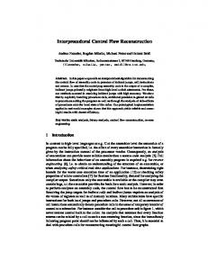
Figure 4: Evaluation of the SPECint2000 results. to us. We furthermore dropped 3 files from 176.gcc, 5 files from 253.perlbmk, 1 file from 254.gap and 1 file from 300.twolf because of compiler crashes. Another file has been removed from 254.gap because the compiler-generated code produced assembler errors. The detailed results are listed in Tab. 3. The control flow has been reconstructed perfectly for 4 of the 11 subdirectories. For the remaining subdirectories we successfully determined the targets of about the half of all indirections except for 176.gcc and 254.gap. The majority of the unresolved indirections results from the 254.gap-directory where a sophisticated memory management implementation is responsible for a huge number of computed calls. Another source of computed calls lies in the 164.gcc directory. In that case the possible call targets can be determined statically because they are stored in global fields containing procedure labels. These calls can be handled analogously to jump tables. Unfortunately definition and use of these fields is spread over several assembly files whereas the current implementation is limited to treating one assembly file at a time. However, the implementation will be extended so that these cases can be covered, too. The results show that on average the number of indirections in assembly code generated with the g21-k compiler is only 1.2% of the contained control flow operations which in turn is 15% of the number of operations in the input
files. 11.7 % of the indirections have been recognized as jump table-based jumps; thus the algorithm found the targets of 98.92 % of the control flow operations. The remaining 1.08 % have been approximated in a safe manner. Without 254.gap only 0.44 % of the control flow operations are indirections of which 38.59 % are recognized as jump tables. Thus the targets of 99.73 % of the control flow operations can be computed precisely. These results are displayed in Fig. 4. The experimental results also show that the reconstruction algorithm works fast even for programs with hundreds of thousands of lines of code. The assembly files from the SPECint2000 benchmark represent 534724 lines of ANSIC code and the complete running time of the reconstruction algorithm was 54.3 minutes. For smaller programs like 181.mcf the reconstruction takes less than one second whereas the reconstruction of 176.gcc takes up to 36 minutes. However, the example of the TriMedia Tm1000 shows that the control flow reconstruction will take more time on assembly code that contains a large percentage of indirections while yielding less precise results. The evaluation of the SPECint2000 for the TriMedia Tm1000 is currently being addressed.
8.
CONCLUSION
In this article a generic control flow reconstruction algorithm for assembly files has been presented. The control flow reconstruction is part of the Propan framework which is a retargetable system for generating machine-specific postpass optimizers from concise hardware specifications written in TDL. Hardware-specific information which has to be known for reconstructing the control flow graph is retrieved from the TDL description. Additionally user-defined functionality can be incorporated to increase the efficiency of the reconstruction, e. g. for recognizing assembly patterns characterizing the begin and end of assembly functions. The control flow reconstruction algorithm is based on an extended program slicing mechanism that also works with unstructured control flow instructions which are typical for assembly programs. In order to determine targets of control flow indirections static information about register contents has to be computed. Program slicing allows to restrict the required evaluation of machine instructions to those instructions that immediately determine the targets of control flow indirections. Experimental results show that this enables the control flow graph of large assembly programs to be constructed in short time. Due to indirect control flow instructions the reconstructed control flow graph cannot be guaranteed to be precise but it does represent a safe approximation. The experimental results show that for the Adsp-2106x Sharc the percentage of control flow instructions whose target address cannot be precisely determined is very small and that the reconstruction can be accomplished in short time. When comparing these results to the TriMedia Tm1000 assembly, it becomes apparent that the quality of the control flow reconstruction depends on the instruction set and hardware features of the target architecture, as well as on the characteristics of the compiler used to generate the assembly files. Especially a larger number of control flow indirections can lead to a longer execution time and less precise control flow graph reconstructions. Currently there is ongoing work to extend the implementation to simultaneously address several assembly files (crossfile reconstruction) and to enhance the efficiency of the implementation in terms of memory consumption and execution speed.
9.
REFERENCES
[1] H. Agrawal. On Slicing Programs with Jump Statements. In Proceedings of the ACM SIGPLAN Conference on Programming Language Design and Implementation, pages 302–312, 1994. [2] Analog Devices. ADSP-2106x SHARC User’s Manual, 1995. [3] C. Cifuentes. Interprocedural Data Flow Decompilation. Journal of Programming Languages, 4(2):77–99, June 1996. [4] C. Cifuentes and A. Fraboulet. Intraprocedural Static Slicing of Binary Executables. Proceedings of the International Conference on Software Maintenance, pages 188–195, October 1997. [5] C. Cifuentes, D. Simon, and A. Fraboulet. Assembly to High-Level Language Translation. Proceedings of the International Conference on Software Maintenance, pages 228–237, August 1998. [6] J.W. Davidson and C.W. Fraser. The Design and Application of a Retargetable Peephole Optimizer. ACM Transactions on Programming Languages and Systems, 2(2):191–202, April 1980.
[7] J.W. Davidson and C.W. Fraser. Code Selection through Object Code Optimization. ACM Transactions on Programming Languages and Systems, 6(4):505–526, October 1984. [8] A. Halambi, P. Grun, V. Ganesh, A. Khare, N. Dutt, and A. Nicolau. EXPRESSION: A Language for Architecture Exploration through Compiler/Simulator Retargetability. Proceedings of the DATE99, 1999. [9] S. Hanono and S. Devadas. Instruction Scheduling, Resource Allocation, and Scheduling in the AVIV Retargetable Code Generator. In Proceedings of the Design Automation Conference 1998, San Francisco, California, 1998. ACM. [10] D. K¨ astner. PROPAN: A Retargetable System for Postpass Optimisations and Analyses. Proceedings of the ACM SIGPLAN Workshop on Languages, Compilers and Tools for Embedded Systems, June 2000. [11] D. K¨ astner. Retargetable Code Optimisation by Integer Linear Programming. PhD thesis, Saarland University, 2000. [12] D. K¨ astner. TDL: A Hardware and Assembly Description Language. Technical Report TDL1.4, Transferbereich 14, Saarland University, 2000. [13] D. K¨ astner. ILP-based Approximations for Retargetable Code Optimization. Proceedings of the 5th International Conference on Optimization: Techniques and Applications (ICOTA 2001), 2001. [14] D. K¨ astner and M. Langenbach. Code Optimization by Integer Linear Programming. In Proceedings of the 8th International Conference on Compiler Construction CC99, pages 122–136, March 1999. [15] D. Lanneer, J. Van Praet, A. Kifli, K. Schoofs, W. Geurts, F. Thoen, and G. Goossens. CHESS: Retargetable Code Generation For Embedded DSP Processors. In [19], pages 85–102. Kluwer, 1995. [16] J.R. Larus and E. Schnarr. EEL: Machine-Independent Executable Editing. In Proceedings of the ACM SIGPLAN Conference on Programming Language Design and Implementation, pages 291–300, 1995. [17] R. Leupers. Retargetable Code Generation for Digital Signal Processors. Kluwer Academic Publishers, 1997. [18] J. Lyle. Evaluating Variations of Program Slicing for Debugging. PhD thesis, University of Maryland, College Park, Maryland, December 1984. [19] P. Marwedel and G. Goossens. Code Generation for Embedded Processors. Kluwer, 1995. [20] Philips Electronics North America Corporation. TriMedia TM1000 Preliminary Data Book, 1997. [21] SPARC International Inc. The SPARC-Architecture Manual, 2nd edition, 1992. [22] B.D. Sutter, B.D. Bus, K.D. Bosschere, P. Keyngnaert, and B. Demoen. On the Static Analysis of Indirect Control Flow in Binaries. In Proceedings of the International Conference on Parallel and Distributed Processing Techniques and Applications (PDPTA), 2000. [23] Henrik Theiling. Extracting Safe and Precise Control Flow from Binaries. In Proceedings of the 7h International Conference on Real-Time Computing Systems and Applications, July 2000. [24] M. Weiser. Program Slicing. In Proceedings of the 5th International Conference on Software Engineering, pages 439–449. IEEE Computer Society Press, March 1981. [25] V. Zivojnovic, J.M. Velarde, C. Schl¨ ager, and H. Meyr. DSPSTONE: A DSP-Oriented Benchmarking Methodology. In Proceedings of the International Conference on Signal Processing Applications and Technology, 1994.