in efforts to save on resources and development time. ... 1 This research was supported in part by The John von Neumann Minerva Center for the Development of Reactive Systems, and by a grant from the Kahn Fund .... ios involving flooding).
Generic Reactive Animation: Realistic Modeling of Complex Natural Systems David Harel and Yaki Setty Department of Computer Science and Applied Mathematics, The Weizmann Institute of Science, Rehovot 76100, Israel {david.harel,yaki.setty}@weizmann.ac.il
Abstract. Natural systems, such as organs and organisms, are largescale complex systems with numerous elements and interactions. Modeling such systems can lead to better understanding thereof and may help in efforts to save on resources and development time. In recent years, our group has been involved in modeling and understanding biological systems, which are perhaps the prime example of highly complex and reactive large-scale systems. To handle their complexity, we developed a technique called reactive animation (RA), which smoothly connects a reactive system engine to an animation tool, and which has been described in earlier publications. In the present paper we show how the basic idea of RA can be made generic, by providing a simple general way to link up any number of reactive system engines — even ones that are quite different in nature — to an animation tool. This results in natural-looking, fully interactive 3D animations, driven by complex reactive systems running in the background. We illustrate this with two examples that link several tools: Rhapsody for state-based specification, the Play-Engine for scenario-based specification, MATLAB for mathematical analysis and the 3DGameStudio for animation. Our examples are both from biology (pancreatic development) and from everyday activities (e.g., gym training).
1
Introduction
Natural systems, such as organs and organisms, are large-scale complex systems that maintain an ongoing interaction with their environment and can thus be beneficially specified as reactive systems [18,23]. This observation has led to quite a lot of work on modeling biology using various software engineering tools and ideas to simulate behaviors in various natural systems. To handle the complexity of natural systems we need even better visualization techniques than those 1
This research was supported in part by The John von Neumann Minerva Center for the Development of Reactive Systems, and by a grant from the Kahn Fund for Systems Biology, both at the Weizmann Institute of Science. Part of this David Harel’s work carried out during a visit to the School of Informatics at the University of Edinburgh, which was supported by a grant from the EPSRC.
2
David Harel, Yaki Setty
used for conventional reactive systems. Indeed, animating natural system reveals unexpected behavioral properties that emerge from the simulations at run-time. These emergent properties are not explicitly programmed, but are often a consequence of massively concurrent execution of basic elements that act in concert as a population [8]. In recent years, our group has been involved in developing a technique called reactive animation, whereby reactive systems whose external form requires more than conventional kinds of GUIs are modeled by languages and tools for the reactivity linked with tools for true animation. In our earlier work on this topic [10] we were motivated by a complex modeling example from biology, which required us to model many thousands of T cells developing, moving around and interacting in the thymus gland, and we wanted the animation to show this actually happening. Our implementation linked the Rhapsody tool, with its statechart model of the system, to a Flash animation front-end, and enabled interaction of the user with the system either via Rhapsody or via the Flash front-end. In that work, the animation was two-dimensional. More importantly, however, the linking itself was binary — one reactive system engine to one animation tool — and it was carried out in an ad hoc fashion. It thus did not provide a mechanism for a more generic reactive animation. In this paper we exhibit a stronger kind of reactive animation, by devising a specific mechanism for linking any number of tools, which may include an animation tool and reactive system engines of different kinds. We illustrate the technique and the underlying principles (as well as the feasibility of 3D reactive animation) by linking up the Rhapsody tool, which supports statecharts and object diagrams, and the Play-Engine [22], which supports live sequence charts (LSCs)[9], to 3DGameStudio (3DGS) [1] for animation and MATLAB[28] for mathematical analysis. Our two reactive engines, Rhapsody and the Play-Engine, which follow state-based and scenario-based approaches, respectively, are connected through a central mechanism with the 3DGS animation tool and the Mathematical GUI. The mechanism is general enough to support and maintain any number of such links. We demonstrate the architecture using two main examples, a complex one from biology and a simpler one closer to everyday life. We will also briefly discuss possible future directions for modeling other natural systems. This paper is supplemented by a website (www.wisdom.weizmann.ac.il/ yaki/GRA), which contains a recording of a short session that was carried out ~ with the different tools linked together. The material on the site also includes several more detailed video clips showing some of the possibilities of the setup. We have deliberately left out in this paper much of the technicalities of the method and its implementation, and have focused instead on the motivation and objectives, and on examples. For readers who are interested in the technical details, there is a technical report that explains things in greater detail, and which can be downloaded from the above website. That report also includes a detailed description of how the architecture is employed, and it briefly suggests directions for standardizing the platform. The site also points to some additional
Generic Reactive Animation
3
supplementary material on the examples (e.g., explanatory clips and interactive illustrations). In our first example, we employ the architecture to model pancreatic development in the mouse, which besides its biological importance turns out to be a highly complex system for modeling, with numerous different kinds of objects. Our model includes a state-based specification linked to a 3-dimensional animated front-end and a mathematical analysis GUI [36]. A prerecorded clip of the simulation at run time is available at www.wisdom.weizmann.ac.il/~yaki/ runs. In this example, Statecharts [16] (in Rhapsody [38]) describe the behavior of the biological objects themselves (e.g., cells), which are represented in the front-end as 3D elements possessing realistic animation attributes. Statistics and analysis of the simulation are shown in a separate GUI (in MATLAB). We discuss how available scientific data is specified as statecharts in Rhapsody, and how scenarios via the LSCs and the Play-Engine may answer the need for mutating the system. The front-end shows the animation continuously, and provides the means to interact with it. The mathematical analysis GUI provides statistics and graphs of the simulation. Generally, the simulation corresponded well with the biology, indicating that the 3D structure emerging from the simulation seems to capture pancreatic morphogenesis in mice. Moreover, this platform enabled to perform a set of in silico experiments, which reproduced results similar to in-vivo efforts and provided a dynamic description. In addition, the model suggested new intriguing results that are currently being tested through collaboration, for an experimentally validation. Our second illustration of the method is a more intuitive running example (pun intended...) of a 3-participant gym training system, which includes a team leader and two team members, running, walking, jumping, crawling and standing, and if needed also swimming and wading (in the special case of scenarios involving flooding). The system also includes a moving camera, sub-viewing abilities, and more. We discuss the way certain parts of the overall controlling behavior are specified in scenarios via the LSCs and the Play-Engine, whereas others, such as the behavior of the participants themselves, are specified using statecharts in Rhapsody. The front-end shows the animation continuously, and provides the means to interact with it. Interactive illustrations of this example are available at http://www.wisdom.weizmann.ac.il/~yaki/GRA/gym.
2
Reactive Animation
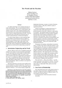
Reactive animation (RA) [10] is a technology aimed at combining state-of-the art reactivity with state-of-the-art animation (Fig. 1A). RA links the effort of reactive system design and the front-end design by bridging the power of tools in the two separate areas. In essence, RA has two arms: One comprises powerful tools and methods for reactive systems development, the heart of which is a rigorous specification of the systems reactivity. The other comprises powerful animation tools to represent the specification as an intuitive, controllable, animated front-end. The animated front-end serves as a communication channel for
4
David Harel, Yaki Setty
better human understanding of the simulation. Technically, RA is based on the view that says that a system is a closely linked combination of what it does and what it looks like. From this stem two separate but closely linked paths: reactive behavior design and front-end design. Implementing a tool for RA poses a number of challenges: accuracy, performance (e.g., CPU usage, memory management, smoothness of the resulting animations), distribution, ease of interaction, openness and platform independence. These should be considered at the architecture level and with the specific functionality chosen. RA was conceived of during an effort to model and simulate the development of T-cells in the Thymus gland [10], where it was implemented using a direct communication socket between a state-based model (using statecharts in Rhapsody) and a 2D animated front-end (using Flash). Our work improves upon [10] by providing a generic, modular and fully distributed multi-party architecture for RA, which also employs 3D animation (Fig. 1B).
Fig. 1. A. Reactive animation: an animation tool is binary linked to a reactive system tool to enable natural-looking, fully interactive animations. B. Implementing generic multi-party reactive animation: reactive engines, animation, mathematical and any other type of tool are linked together using a central routing server (a star topology). Tools communicate through a TCP socket and transmit XML based messages, enabling a fully distributed, platform-independent implementation (in a way similar to Soap).
Generic Reactive Animation
3
5
Implementation Architecture
The architecture of our examples includes two reactive engines supporting two different modeling approaches: a state-based, intra-object approach, and a scenariobased, inter-object approach. The reactive engines are linked up to a threedimensional animated front-end and a mathematical analysis GUI, using a central routing server. In principle, the architecture can be extended by using any number of additional components of any related kind (e.g., a 2D front-end using Flash).1 Below we briefly describe each of the architectural components, a detailed technical report is available at www.wisdom.weizmann.ac.il/~yaki/ GRA/. The Central Routing Server: The server was implemented as a multi-threaded executable application. Each thread serves as a communication plug-in for one architectural component. A TCP socket is initialized upon registration to the server, enabling message transmission and XML parsing. See the supplementary technical report for a more detailed description. The State-Based Specification: We use the language of statecharts [17] and the Rhapsody tool [38] to implement state-based specification. Statecharts are naturally suited for the specification of objects that have clear internal behavior, an attribute we call intra-object. Together with object model diagrams, they provide a graphical representation of the dynamics of objects using states, transitions, events, and conditions [20]. The language makes it possible to visualize the behavior of an object in a way that emphasizes the elements in its life-cycle. Rhapsody is a model-driven development environment supporting statecharts and object model diagrams (see [20]), and can be viewed also as a UML tool. It enables object-oriented design, with full execution of the statechart-rich models, and full code generation. Table 7, top details a representative example for a state-based specification. The Scenario-Based Specification: We use the language of LSCs, live sequence charts [9] and the Play-Engine [22] to implement scenario-based specification. LSCs are scenario-based, and inter-object in nature, and are particularly fitting for describing behavioral requirements. LSCs extend classical message sequence charts (MSCs) with logical modalities, depicted as hot and cold elements in the charts. The language thus achieves far greater expressive power than MSCs, and is comparable to that of temporal logic. In particular, LSCs can specify possible, mandatory and forbidden scenarios, and can be viewed as specifying multi-modal restrictions over all possible system runs. An LSC typically contains a prechart and a main chart. The semantics is that if the scenario in the prechart executes successfully, then the system is to satisfy the scenario given in the main chart. The Play-Engine is the tool built to support LSCs, that 1
In earlier work of our group, we developed InterPlay, which is a different kind of technique to connect reactive system engines, based on pairings of connections [4].
6
David Harel, Yaki Setty
enables a system designer to capture behavioral requirements by ‘playing in’ the behavior of the target system, and to execute the specified behavior by ‘playing out’. In the play-out phase the user or an external component executes the application as if it were the real system. Table 7, bottom details a representative example of a scenario-based specification. The 3D Animated Front-End: The front-end was implemented using a three dimensional authoring tool (3D Game Studio (3DGS) [1]), which supports real time rendering of 3D animation. In 3DGS, objects can have associated actions, which appear as part of its attributes. The scripting language of 3DGS, C-Script, enables control of animation objects (e.g., changing an attribute) and supports object oriented programming. We choose to add a controlling GUI to our system as part of the front-end (as was done also in the thymus model [10]). However, in more complex systems such a GUI could very well complicate the front-end and should be designed as a different architectural component, possibly using a GUI-building tool. Mathematical Analysis GUI: We designed a mathematical analysis GUI using MATLAB from MathWorks [28], which is a high-level language and interactive environment for computational tasks. This GUI generates various graphs and statistics based on data received from the simulation. Similar mathematical analysis tools such as Mathematica from Wolfram Research, can also be plugged-in the architecture. The Architecture at Run-Time: Each component, when executed, initiates a connection with the Central Routing Server. The setting of components in the architecture enables pairwise message transfer between them. At run-time, message passing drives the simulation in the participating components. For example, messages from the reactive engines (i.e., Rhapsody and Play-Engine) drive the animation in the front-end. Table 7 describes in detail possible runs of one of our examples.
4
Modeling a Large-Scale Biological System
We have employed the proposed generic RA setup to model the development of the pancreas, a highly complex system, containing numerous objects. The pancreas is an essential organ, which is involved in regulation of metabolic and digestive pathways. During development, it takes on an interesting threedimensional cauliflower-like shape. A prerecorded run of the simulation is available at www.wisdom.weizmann.ac.il/~yaki/runs Abnormal functioning of the pancreas leads to lethal diseases such as pancreatitis and diabetes. Our model includes a comprehensive state-based specification that results from analyzed scientific data. It is linked to an animated front-end and a mathematical analysis GUI. In the future, we plan to link these two also with a scenario-based specification to simulate mutations (e.g., defective blood
Generic Reactive Animation
7
vessel). In [36], we provide details of this the work and discuss the intriguing novel ideas that emerged from the model. See www.wisdom.weizmann.ac.il/ ~yaki/abstract/ for a short description. Modeling Pancreatic Development: We modeled pancreatic development as an autonomous agent system [5] in which cells are autonomous entities that sense the environment and act accordingly. The cell object in the model consists of three elements, the nucleus, the membrane and the cell itself. The nucleus operates as an internal signaling unit that expresses genes to drive the development, while the membrane acts as an external signaling unit that senses the environment and alerts the cell. The cell itself changes states in response to the various signals (see Fig. 2). The environment was modeled as a computational grid, with values that designate concentrations of biological factors. Various biological components participate in the process by regulating factors in the environment. Each of these was specified as an object accompanied by a statechart to describe its behavior. Cells however, are considered as the basic objects, and the progress of the simulation/execution relies very much on their behavior. An execution of the model is initiated with approximately 500 cells, which, among other processes, proliferate and create new instances. A typical execution ends with almost 10, 000 objects.
Fig. 2. The model for a cell as an autonomous agent accompanied with its visualization (top-left)
8
David Harel, Yaki Setty
Designing an Animated Front-End: We visualize the simulation in an animated front-end, which we built based on what is depicted in the literature. Each one of the participating components is represented as a 3D element possessing attributes to represent change in location and behavior (Fig. 3A). For example, the cells are represented in the front-end as spheres. At run time, an instance of a cell directs its corresponding animated sphere according to its active state. A differentiated cell might, for example, change its color to depict the new stage. As the simulation advances, the cells dynamically act in concert to form the cauliflower-shape structure of the pancreas (Fig. 3B). At any stage, the user can halt the simulation and query objects or interact directly with the emerging structure (e.g., ‘slice’ the structure) (Fig. 3C). Mathematical Analysis GUI: We designed a GUI in MATLAB to provide mathematical analysis of the simulation. The GUI continuously receives data from the reactive engine, analyzes it and provides graphs and statistics (for example, graphs of cell population, proliferation rate etc.). It thus enables the user to evaluate the dynamics of the simulation over time. Fig. 3D shows a snapshot of a graph that displays the cell count over time. In general, the system developer can design many graphs and statistics, which are related to the relevant system and whose data is gleaned from the model.
Fig. 3. A. 3D Animated front-end for the pancreatic development. B. The pancreatic structure emerging from the simulation. C. User interaction with the simulation, the simulation was halted and a cross-section cutting was triggered. D. Mathematical analysis of the pancreatic development: number of cells as function of time.
Generic Reactive Animation
9
Specifying Mutations in the Simulation: In the pancreas project, as well as as in modeling other large-scale natural systems, scenario-based programming may help in specifying mutations in a rather natural way. A typical mutation scenario should specify the changes in the model that correspond to relevant mutations between elements in the system. At run-time, the user may trigger relevant scenarios to mutate the system and then watch the effect on the simulation. For example, a mutation scenario in pancreatic organogenesis would specify the effect of a defective blood vessel on the participating elements, in particular cells. In the past, work in our group has shown scenario-based programming to be beneficial for modeling biology. For example, it was the dominant tool used for the specification and verification of certain developmental aspects in the reproductive system of the C. elegans nematode (see e.g., [26,27,35,25]). The Pancreas at Run-Time: Once the model is executed, instances of the Cell are created and appear in the front-end as a sheet of red spheres on the proper location on the flat endodermal Gut. Once a Cell instance is created, one state in each concurrent component of its statechart is set to be in active state. At this point, the Cells are uniform and their active states are set to the initial states . In parallel, the environment is initiated and defines the initial concentrations of factors in the extracellular space. As the simulation advances, cells respond to various events (e.g., the concentration of factors in their close vicinity) by changing their active states accordingly. Hence, the sheet loses uniformity at a very early stage of the simulation. As the simulation advances, among other things, cells are differentiated, proliferated and move. The processes are driven by many extracellular events (e.g., from the membrane) and intra-cellular events (i.e., from the nucleus). These events change the active states in orthogonal specifications through the various stages of the cell’s life cycle. For example, the proliferation process is initiated by extra-cellular signals when the membrane senses relevant factors and generates a chain of inter-cellular events (in the cell and the nucleus) that promote cell division. Proliferation ends when the Cell duplicates itself by creating an identical instance. In turn, a message is sent to the front end, which creates a new identical sphere corresponding to the new Cell at the proper location. The cell population acts in concert to drive the simulation, by promoting various decisions in individual cells. Consequently, messages are continuously being sent between the different components in the architecture, in order to drive the simulation. The process is displayed in parallel in each one of the components. The state-based specification highlights the active state of the different objects and, at the same time, the front-end and the mathematical GUI continuously visualize and analyze the simulation. Once scenario-based specification is combined to the model, interplay between scenario- and state-based specifications will drive mutations in the simulation. The user would be able to trigger mutations through the various tools in the model and then watch the mutated behavior through the animation and
10
David Harel, Yaki Setty
analysis. Such mutations may be tested in vivo on the real system through laboratory collaboration.
5
A Team Training Model
The second example we describe here is a simple, yet representative, model. It involves gym training sessions for a team of three: a team leader and two team members. The team leader performs various actions at different speeds, and the team members follow suit, after a short “comprehension” delay. Team members, however, are not as physically fit as the team leader, and need to rest while performing certain fast actions. In addition, the team leader reacts to environmental changes (e.g., a Flood) and performs an appropriate set of actions to handle such situations. The model implements a state-based and scenario-based model, linked to an animated front-end. Detailed descriptions of two execution examples of the model are given in Table1. Also, http://www.wisdom.weizmann.ac.il/~yaki/ GRA/gym contains several self-explanatory video clips. Modeling Team Behavior Using Statecharts: We used the state-based approach to specify the team’s actual behavior. Our Rhapsody model includes three classes: the team leader, the team member and the team. We demonstrate statecharts using two team members, however, the model can be easily extended to handle any number thereof. The behavior of each model element is specified by a different statechart. The statecharts of the leader and a member describe the action and the speed taken and are very similar (see Table2 for greater details). The statechart of the team handles interactions with the environment. Specifying Team Training Tasks Using LSCs: We used the scenario-based approach to specify training tasks for the team. The Play-Engine model specifies several training task, which include a set of instructions for the team and for the environment. Four different tasks have been specified: Escape, Flood, Storm and Volcano Eruption. Each of these initiates a different scenario. Triggering a new task while another is being executed causes a violation and the new LSC terminates. An instruction message (e.g., crawl, jump, swim) triggers an LSC that forces the engine to execute a specified set of messages. In addition, LSCs specify camera control and environmental changes (see Table2 for greater details). Designing an Animated Front-End: The front-end for the model consists of a real-time 3D animation of the training exercise. Animated renditions of a team leader and a team member were created based on the cbabe model of 3DGS. The participants perform various actions such as walking, swimming, wading etc. The user may query the model by clicking an animated figure, and the relevant data (e.g., ID, current action) is displayed next to it. Environmental changes such as a flood may occur and the animated front-end displays the change accompanied by matching sound effects. The GUI portion of the front-end enables the user to
Generic Reactive Animation
11
trigger an instruction to the team (e.g., to jump fast) or to assign a task (e.g., to escape), respectively. He or she also controls the camera’s activity and may query the running simulation. Team Training at Run-Time: Once the model is executed, the state-based specification of the team behavior is initiated and the active state of each player is set to Stand (i.e., the initial state). As the simulation advances, various events (either internal or external) change the active state of the players. For example, instructions from the leader to the members are internal events of a team that drive within the state-based specification. Similarly, external events from the scenario-based specification, describing team tasks (e.g., flood), directs the active state of state-based specification. The behavior of the model is continuously visualized at the front-end in various manners. For example, when a flood task is initiated, a water wave appears at the front-end and the team starts wading. At every time-point, the user may interact with the model so as to trigger different behaviors of the team (e.g., change the action of team members).
6
Additional RA examples
We are currently looking into using our techniques in additional biological modeling projects. We use the generic reactive animation architecture to visualize behaviors as part of the GemCell project [2]. GemCell contains a generic statechart model of cell behavior, which captures the five main aspects of cell behavior (proliferation, death, movement, import and export). This generic model is coupled with a database of biological specifics (DBS), which holds the information about the specific cellular system. Modeling a particular segment of biology involves setting up the DBS to contain data about the specific behaviors and responses of the particular kinds of cells in the system under description. During execution, statecharts read in the specific data and the combination runs just as described in the model above. We have employed the generic reactive animation architecture to link the GemCell model (in Rhapsody) with a 2D animated from-end (in Flash). At run time, the front-end continuously visualizes the behavior of numerous cells. The visualization clarifies the underlying principles in simulation. This project is still in its early stages of development. In addition to this, we have tested the genericity of our architecture on some other examples, with different tools. We have a ‘traffic handing’ model that uses our architecture to link the scenario-based programming tool, the Play-Engine, to a 2D animated front-end using Flash. Also, we have designed a ‘police at work’ game using S2A[21], an aspectJ-based tool for scenario-based programming, linked to a 2D animated front-end in Flash. Further details of these examples appear in www.wisdom.weizmann.ac.il/ yaki/GRA. ~
12
7
David Harel, Yaki Setty
Discussion
In the last few years, increasing interdisciplinary work combines experimental results with theoretical models in order to explain various natural systems (see e.g., [3,7,15,29]). Another type of modeling work formalizes gene expression and protein activity using a variety of mathematical and computational tools (for example, see [6,24,31,32,33]). However, most of the relevant work ignores multiple concurrent activities and focuses on a single mechanism in the entire system. An example for comprehensive modeling is the beating heart project [30], which formalizes the electric activities in the heart. However, by its mathematical nature, the model interactivity and real time animation are limited since simulations require much computation time. Recently, various work uses computational modeling approaches for natural systems. In [14], hybrid automata are used to model the Delta-Notch mechanism, which directs differentiation in various natural systems. In [12], computational challenges of systems biology are described and various approaches for achieving them are discussed. A similar motivation for model-driven engineering approaches is discussed in [34]. Recently, in [13] computational and mathematical approaches are reviewed and the term executable biology is used to describe the kinds of modeling carried out in our group, and recently also elsewhere. In [39], a model for a eukaryotic cell is built, in which a UML class diagram was used to formalize the relations between a cell and its sub-cellular elements. The setup was empowered by specifying behavior of different cell types (e.g., red blood cell) using the ROOM formalism. A similar approach was employed in [37] to model the Ethylene-Pathway in Arabidopsis thaliana using statecharts and LSCs. As mentioned, the present paper is an extension and generalization of our previous work on reactive animation [10], which was motivated by the need for a clean way to bridge the gap between how objects behave and how that behavior should show up on the screen. The idea was to separate the reactivity from the visualization, making it possible to choose the best tools for each, and thus enjoying the benefits of both worlds. Having a reactive engine that controls the simulation while an animated front-end monitors the visualization, makes it possible to model large-scale systems with many objects and interactions. Each agent in the reactive engine has a corresponding animated figure in the frontend, and since the two models are separate, they can be designed by specialists in their particular fields using any state-of-the-art tools. In [10], reactive animation was illustrated by simulating the development of T-cells in the Thymus gland, and it was implemented using a direct communication socket between a state-based model (statecharts in Rhapsody) and a 2D animated front-end (in Flash). The present paper provides a generic, modular and fully distributed architecture, with the ability to link multiple reactive engines, and it illustrates the feasibility of reactive animation with a three-dimensional visualization. Furthermore, this platform was used beneficially for the realistic modeling of pancreatic development, a complex and large-scale biological system. Moreover, the model reproduced results of relevant experiments and suggested new intriguing ideas [36].
Generic Reactive Animation
13
We believe that our biological models emphasize the benefit for modeling complex large-scale systems using reactive animation. In the models, the visualized concurrent execution of the basic elements revealed properties that were not explicitly programmed into the model. Rather, they emerge from the concurrent execution of cells as a population. For example, in the pancreas model, we found that concurrent execution of pancreatic cells gives rise to a property that corresponds well with first transition clusters found to appear early in the developing organ in vivo [36]. Similarly, the concurrent execution of T-cell development in the thymus led to the emergence of competitive behavior between the cells [11]. Moreover, using the model, we analyzed and studied these properties and suggested some insights into the phenomena [8,11,36]. In general, since emergent properties are dynamic properties of a population, it is rather difficult to predict them from the model’s static specifications. At the animated front-end, which visualizes the simulation, the phenomenon is often easily seen and can then be carefully examined against the literature for a biological explanation. While we have used a number of examples to illustrate generic reactive animation, we find the technique particularly beneficial for large-scale biological systems. We envision that in the long run, the pancreas project may lead to new insights about pancreas-related diseases, such as diabetes. Furthermore, we feel that generic RA my perhaps help in efforts to build an in-silico organ or organism (see, e.g., [19]). Acknowledgments. We would like to thank Shahar Maoz and Gera Weiss for their help and support in setting the architecture and designing the examples.
14
David Harel, Yaki Setty
Table 1: Illustration of two execution examples of the team training model (for interactive illustration and recorded clips see http://www.wisdom.weizmann.ac.il/~yaki/GRA/gym) . Illustration of the Architecture: The Team Training Model: Message transmission between the architectural components of the model: The state-based model (ST, at top left); The scenario-based specification (SC, at bottom left); and the animated front-end (FE, at middle right).
Example 1: Medium Speed Jumping Participating components: FE, ST Description: When the user sets the speed scroll bar to medium and clicks the jump button, FE notifies (i.e., sends a message to) ST about the instruction (1). Accordingly, the team object in ST generates an inner event to set the statechart of the team leader to jump at medium speed (i.e., the Action sub-statechart moves to the Jumping state and the Speed sub-statechart is set to Medium). After a predefined time interval, the team object generates another event for the statecharts of each of the team members. Upon entering the Jumping state, ST notifies FE to animate the action (2). Consequently, the animated team leader jumps, and the team members follow suit. The user can change the camera’s position to view the team from different angles. Camera relocation, however, has no effect on the running simulation. During a run of the system, the user may query the model or relocate the camera. When a query is requested, FE notifies ST (1), which provides the appropriate information. Changes in the camera, however, do not interact with the reactive engines.
Example 2: Flood Training Task Participating components: FE, SC,ST Description: The user assigns a flood task to the team by clicking on the appropriate button. Consequently, FE notifies SC and the flood LSC is activated (3), initiating the scenario. The first message in the flood LSC is a running instruction for the team. Consequently, the run LSC is activated, and it notifies ST to run at a slow speed (4). Later on, a message in the flood LSC instructs the environment to initiate a flood. The FloodAlert LSC is activated and notifies FE (5). Accordingly, a water layer is displayed and a corresponding splashing sound is played. Immediately after this, the swim LSC is activated and it notifies ST. The swim message enables a forbidden element in the run LSC, causing the run LSC to exit. Again, the swim LSC notifies ST, which in turn notifies FE(2). The flood LSC completes after it instructs the team to walk, the environment to end the flood, and the team to stand (i.e., to stop moving). At this point, there are no more LSCs active in SC, the statecharts of ST are all in the standing state, and the animated figures in FE are standing, ready for the next task. In case a fast speed action is taken, each of the two team member objects will enter a resting state after some time. Consequently, ST notifies SC(6) and FE(2). Concurrently, the team member in FE changes its appearance to resting, an SC in SC is triggered, and it notifies FE (5) to activate the team member’s camera.
Generic Reactive Animation
15
Table 2: Sample of the model: statechart behavior of the team leader (top), and LSC specification describes Flood task(bottom) Samples of the Model
Description The team leader’s statechart: The behavior of the team leader is specified by a statechart with four orthogonal components (i.e., concurrent sub-statecharts). The most important of these are Action and Speed, which specify the team leader’s current action (e.g., running, working) and current speed (slow, medium, fast), respectively. The statechart of a team member is similar, but it has an additional behavioral element: a team member takes a short rest while a fast action is performed. To add this behavior, a superstate was added to a team member’s Action subchart and an internal statechart was added to the fast state. The other two orthogonal components are less important; they serve as internal and external communicators.
The flood LSC: assigning a flood task triggers the flood LSC, which initiates the following scenario: the team participants run until the water level rises, and then they swim until the water level is low enough to walk. When the flood is over, the team participants stop motion, and stand, ready for a new task. During task execution, the run instruction triggers an LSC that instructs the team to run at an increasing speed. When the swim instruction is taken, the run LSC terminates.
16
David Harel, Yaki Setty
References 1. 3D Game Studio, www.3dgamestudio.com. 2. Amir-Kroll, H., Sadot, A., Cohen, I. R., Harel, D.: GemCell: A Generic Platform for Modeling Multi-Cellular Biological Systems, T. Comp. Sys. Biology to appear (2007) 3. Axelrod, J. D.: Cell Shape in Proliferating Epithelia: A Multifaceted Problem, Cell 126, 643–645 (2006) 4. Barak, D., Harel, D., Marelly, R.: InterPlay: Horizontal Scale-Up and Transition to Design in Scenario-Based Programming, In: Lectures on Concurrency and Petri Nets, Lect. Notes in Comp. Sci. 3098, 66–86 (2004) 5. Brooks, R. A.: Elephants Don’t Play Chess, Robotics and Autonomous Systems 6, 3–15 (1990) 6. Cardelli, L.: Abstract Machines of Systems Biology, T. Comp. Sys. Biology 3, 145– 168 (2005) 7. Ciliberto, A., Novak, B., Tyson, J. J.: Mathematical Model of the Morphogenesis Checkpoint in Budding Yeast, J. Cell. Biol. 163, 1243–1254 (2003) 8. Cohen, I. R., Harel, D.: Explaining a Complex Living System: Dynamics, Multiscaling and Emergence, J. R. Soc. Interface 4, 175–182 (2007) 9. Damm, W., Harel, D.: LSCs: Breathing Life into Message Sequence Charts, Formal Methods in System Design 19, 45–80 (2001) 10. Efroni, S., Harel, D., Cohen, I. R.: Reactive Animation: Realistic Modeling of Complex Dynamic Systems, IEEE Computer 38, 38–47 (2005) 11. Efroni, S., Harel, D., Cohen, I. R.: Emergent Dynamics of Thymocyte Development and Lineage Determination, PLoS Comput. Biol. 3, e13 (2007) 12. Finkelstein, A., Hetherington, J., Li, L., Margoninski, O., Saffrey, P., Seymour, R., Warner, A.: Computational Challenges of Systems Biology, IEEE Computer 37, 26–33 (2004) 13. Fisher, J., Henzinger, T. A.: Executable cell biology, Nat. Biotechnol. 25, 1239– 1249 (2007) 14. Ghosh, R., Tomlin, C.: Symbolic Reachable Set Computation of Piecewise Affine Hybrid Automata and its Application to Biological Modelling: Delta-Notch Protein Signalling, Syst. Biol. (Stevenage) 1, 170–183 (2004) 15. Gibson, M. C., Patel, A. B., Nagpal, R., Perrimon, N.: The emergence of geometric order in proliferating metazoan epithelia, Nature 442, 1038–1041 (2006) 16. Harel, D.: Dynamic Logic, In: D. Gabbay and F. Guenthner, editors, Handbook of Philosophical Logic, Reidel, 2, 497–604 (1984) 17. Harel, D.: Statecharts: A Visual Formalism for Complex Systems, Sci. Comput. Programming 8, 231–274 (1987) 18. Harel, D.: A Grand Challenge for Computing: Full Reactive Modeling of a MultiCellular Animal, Bulletin of the EATCS 81, 226–235 (2003) 19. Harel, D.: A Turing-like test for biological modeling, Nat. Biotechnol. 23, 495–496 (2005) 20. Harel, D., Gery, E.: Executable Object Modeling with Statecharts, IEEE Computer 30, 31–42 (1997) 21. Harel, D., Kleinbort, A., Maoz, S.: S2A: A Compiler for Multi-modal UML Sequence Diagrams, In: FASE, 121–124 (2007) 22. Harel, D., Marelly, R.: Come, Let’s Play: Scenario-Based Programming Using LSCs and the Play-Engine. Springer-Verlag (2003)
Generic Reactive Animation
17
23. Harel, D., Pnueli, A.: On the Development of Reactive Systems, In: K. R. Apt, editor, Logics and Models of Concurrent Systems, NATO ASI Series F-13, 477–498 (1985) 24. Heath, J., Kwiatkowska, M., Norman, G., Parker, D., Tymchyshyn, O.: Probabilistic Model Checking of Complex Biological Pathways, In: C. Priami, editor, Proc. Computational Methods in Systems Biology (CMSB’06), Lecture Notes in Bioinformatics 4210, 32–47 (2006) 25. Kam, N., Harel, D., Kugler, H., Marelly, R., Pnueli, A., Hubbard, E. J. A., Stern, M.: Formal Modeling of C. elegans Development: A Scenario-Based Approach, In: C. Priami, editor, Proc. Int. Workshop on Computational Methods in Systems Biology (CMSB 2003) 4–20 (2003) 26. Kam, N., Kugler, H., Appleby, L., Pnueli, A., Harel, D., Stern, M. J., Hubbard, E. J. A.: A scenario-based approach to modeling development (I): Rationale, hypothesis testing, simulations and experimental follow-up, submitted (2007) 27. Kugler, H., Kam, N., Marelly, R., Appleby, L., Pnueli, A., Harel, D., Stern, M. J., Hubbard, E. J. A.: A scenario-based approach to modeling development (II): A prototype model of C. elegans vulval cell fate specification, submitted (2007) 28. The MathWorks, www.mathworks.com. 29. Nelson, C. M., Vanduijn, M. M., Inman, J. L., Fletcher, D. A., Bissell, M. J.: Tissue geometry determines sites of mammary branching morphogenesis in organotypic cultures, Science 314, 298–300 (2006) 30. Noble, D.: The heart is already working, Biochem. Soc. Trans. 33, 539–542 (2005) 31. Priami, C., Quaglia, P.: Modelling the dynamics of biosystems, Briefings in Bioinformatics 5, 259–269 (2004) 32. Regev, A., Shapiro, E.: Cellular abstractions: Cells as computation, Nature 419, 343 (2002) 33. Regev, A., Silverman, W., Shapiro, E.: Representation and simulation of biochemical processes using the pi-calculus process algebra, In: Pacific Symposium on Biocomputing, 459–470 (2001) 34. Roux-Rouqui´e, M., da Rosa, D. S.: Ten Top Reasons for Systems Biology to Get into Model-Driven Engineering, In: GaMMa ’06: Proc. of the 2006 international workshop on Global integrated model management 55–58 (2006) 35. Sadot, A., Fisher, J., Barak, D., Admanit, Y., Stern, M. J., Hubbard, E. J. A., Harel, D.: Towards Verified Biological Models, IEEE/ACM Trans. Comput. Biology and Bioinformatics to appear (2007) 36. Setty, Y., Cohen, I. R., Dor, Y., Harel, D.: Four-Dimensional Realistic Modeling of Pancreatic Organogenesis, submitted (2007) 37. Taubner, C., Merker, T.: Discrete Modelling of the Ethylene-Pathway, In: ICDEW ’05: Proceedings of the 21st International Conference on Data Engineering Workshops 1152 (2005) 38. Telelogic, www.telelogic.com. 39. Webb, K., White, T.: Cell Modeling with Reusable Agent-based Formalisms, Applied Intelligence 24, 169–181 (2006)