Genetic algorithm optimization of precast hollow core slabs Luca Sgambi1a, Konstantinos Gkoumas*2b and Franco Bontempi2c 1
Department of Civil and Environmental Engineering, Politecnico di Milano, Piazza Leonardo da Vinci 32, 20133 Milan, Italy 2 Department of Structural and Geotechnical Engineering, Sapienza University of Rome, Via Eudossiana 18, 00184 Rome, Italy
(Received
, Accepted
)
Abstract. Precast hollow core slabs (HCS) are technically advanced products in the precast concrete
industry, widely used in the last years due to their versatility, their multipurpose potential and their low cost. Using three dimensional FEM (Finite Element Method) elements, this study focuses on the stresses induced by the prestressing of steel. In particular the investigation of the spalling crack formation that takes place during prestressing is carried out, since it is important to assure the appropriate necessary margins concerning such stresses. In fact, spalling cracks may spread rapidly towards the web, leading to the detachment of the lower part of the slab. A parametric study takes place, capable of evaluating the influence of the tendon position and of the web width on the spalling stress. Consequently, after an extensive literature review on the topic of soft computing, an optimization of the HCS is performed by means of Genetic Algorithms coupled with 3-D FEM models. Keywords: Hollow Core Slabs, Genetic Algorithms, Finite Element Method, Optimization, Soft
Computing, Spalling, Rotating Crack Model, Prestressed Reinforced Concrete Structures.
1. Introduction Precast hollow core slabs (HCS), also known as void slabs or simply hollow slabs, are technically advanced products in the precast concrete industry, widely used in the last years due to their versatility, their multipurpose potential and their low cost. These are a particular kind of concrete slabs that can be prestressed or conventionally reinforced. In the first case, the prestressing steel, which is the only reinforcement of the HCS, is inserted in the form of strands or wires, placed in the lower part of the vertical concrete part between two adjacent cores (webs), where the concrete segment allows the optimal wire or strand bonding. The steel is prestressed before the insitu concrete topping is poured, and transfers the prestressing force to the concrete in the transfer zone. The bonding of the prestressed reinforcement is heavily influenced by
a b c
Assistant Professor, E-mail:
[email protected] Research Associate, Corresponding Author, E-mail:
[email protected] Professor, E-mail:
[email protected]
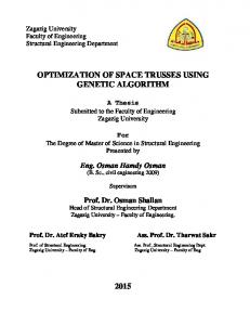
the condition of the concrete in the transmission zone (along a distance equal to the transmission length). The degree of bonding is influenced by several parameters (e.g. concrete type), but it is mostly influenced by the presence or absence of cracking in the transmission zone (Buettner and Becker 1998). Capuano et al. (2002) deal with the HCS design requirements and production technique. Fig. 1 shows the principal cracks due to the tensile stresses at the slab head in a prestressed precast shallow core slab (adapted from Capuano et al. 2002): splitting cracks: caused by stresses resulting from the development of prestressing in the anchorage zone, that may generate traction stresses in the concrete. bursting cracks: a local effect, generated by the strand slippage into the slab end while the former widens slightly on being cut. spalling cracks: occurring above the axis of the strands in the HCS end zone, caused also by the development of prestressing in the concrete at the slab ends where only the lower part holding the strands begins to be prestressed. Splitting cracks can occur only in elements prestressed with pretensioned tendons, while bursting and spalling cracks can occur both in elements with pretensioned or post-tenioned tendons. Stress checks for spalling are particularly important. The spalling stress has its peak at the very end of the slab and if the stress is large enough it develops into horizontal cracks which are commonly known as "crocodile mouths”, normally located where the web has a minimum thickness. Such cracks start at the end of the slab and run rapidly as long as needed until the equilibrium is found. This distance is usually rather small and never leads to large delamination. Since a HCS has to go through additional stages that can damage its load bearing capacity (i.e. demoulding, transportation storage and erection), it is important to assure the appropriate necessary margins concerning the stresses that take place during prestressing (EN 1168+A2, 2010).
σsp
Figure 1. Different tensile crack phenomena in HCS (splitting, bursting, spalling).
The tensile strength of HCS has been studied extensively in literature. In an early study, Pisanty and Regan (1991) carried out extensive experimental tests on prestressed HCS, and obtained useful results on the tensile strength of the web as a function of the web geometry and for different specimen locations. An analytical investigation on the above is found in Pisanty (1992). More recently, for what concerns their structural behavior in general, Girhammar and Pajari (2008), after providing a literature review on the topic, focus, both analytically and experimentally, on the shear strength, with specific reference on the influence of the concrete topping. Gálvez et al. (2009), study with an experimental procedure the splitting failure of the concrete, induced by the action of the indented wire, in hollow core slabs and prestressed joists. They focus on the influence of the distance between wires, the thickness of concrete cover and the depth of the wire indentations in the bond-splitting. On the later, the authors propose also a bond model that takes into account the possible failure of concrete by splitting. Benítez and Gálvez (2011), present an analytical model for simulating the bond between steel and concrete, in precast prestressed concrete elements, which allows evaluating the bond stress in the transmission zone where bond stress is not constant, during the prestressing force release. Araujo et al. (2011) perform numerical non-linear modeling on HCS, and propose a methodology for the shear design. Chang et al. (2008) focus on the structural behavior of HCS subjected to fire, proposing more realistic numerical models that account for the membrane action of the RC topping layer. The shear resistance of HCS is also investigated for HCS connected to steel beams (Lam et al. 2000; Lam, 2002; Hegger et al. 2009) and wall panels (Wilson et al. 2008), HCS strengthened with carbon fiber polymers (Elgabbas et al. 2010) and using fiber reinforced concrete (Cuenca and Serna 2013). In this study, the stresses arising from prestressing are analyzed by means of three dimensional FEM (Finite Element Method) elements. A parametric study is carried out, capable of evaluating the influence of the tendon position and of the web thickness on the spalling stress. This is of particular importance since the spalling stress relates directly with the structural robustness, intended as the ability of a structure to maintain localized an initial damage and avoid the propagation of failures in the system (for some of the latest achievements on the topic see Starossek and Haberland 2011 and Giuliani, 2012). A comparison between the spalling stresses obtained with the FE analysis and those from European Standards is also performed. After this, an optimization of the slab dimensions is carried out using a soft computing method (Sgambi, 2008 provides an overview of artificial intelligence methods in the civil engineering field) in particular using a genetic algorithm approach. Topology optimization problems (that is to optimize for a specific performance the material layout within a given design space, for a given set of loads and boundary conditions) are common in civil engineering. Literature is vast, also focusing on the specific topic (concrete and non-linear structures). Usually, when distributing concrete, steel and voids, the optimized design resembles a strut-and-tie model, thus, principal applications of topology optimization in reinforced concrete design is in generating strut-and-tie models. Guan (2005) applies topology optimization on reinforced concrete deep beams with web openings under stress and displacement constraints. Bogomolny and Amir (2012) optimize the design of reinforced concrete structures and provide examples, discussing also issues arising from nonlinear analysis. In their formulation, focusing on the distribution of concrete, steel and void of simple structures, the objective is to maximize the end compliance. Fairbairn et al. (2004) focus on cracking of massive concrete structures (a small concrete dam) by means of a coupled thermo-chemo-mechanical model in FEM code and genetic algorithm optimization. Tomás and Martí (2010) apply optimization methods for the optimum geometric design of concrete shells using different objective functions
(strain energy, weight or tensile stress). Del Coz Díaz et al. (2011) minimize the weight of a hollow concrete masonry block. In their problem the global stiffness (objective function) is maximized subject to a volume reduction constraint. More recently, Amir (2013) proposes a methodology and applies structural optimization to different concrete structures (a deep beam, a corbel and a wall with openings), optimizing the distribution of both concrete and reinforcement bars. Luo and Kang (2013) focus on the layout optimization problem of reinforced concrete structures, implementing a hybrid constraint-reduction strategy, thus minimizing the structural mean compliance under yield stress constraints on concrete elements and a volume constraint on the steel elements. As stated earlier, in this study, coupled FEM models (micro- and meso-scale) are used together with genetic algorithm optimization, for minimizing the HCS volume subject to resistance and spalling stress criteria. To this point, it is useful to provide a brief overview of SC methods and their applications in the civil engineering field. The concept of Soft Computing (SC), nowadays a formal computer science area of study, was formally introduced by Zadeh in 1981 (Zadeh, 1997): it is a whole methodology directed to exploit the tolerance to the imprecision and to the uncertainty to achieve tractability and robustness with little computational cost, being the human mind the model of reference. These methods of analysis are therefore suitable for the treatment of problems in which an exact solution does not exist or if exists it is a very complex one. This issue is important for complex structural systems (Bontempi et al. 2008), with the complexity characterized by the fact that every system includes physical parts (hardware), logical aspects (software) and is designed and operated by people (humanware). There are three principal constituents of SC: artificial neural networks, fuzzy systems and evolutionary algorithms. Artificial Neural Networks (ANN) are systems of elaboration of the information inspired by the biological neural network. They are characterized for their robustness and flexibility and for their ability to generalize. In the last years ANN are applied in the civil engineering field, in structural design (Adeli and Park, 1995) reliability engineering and structural identification (Ceravolo et al. 1995; De Stefano et al. 1999; Kim et al. 2000; Jiang and Adeli, 2005; Arangio and Bontempi, 2010; Arangio and Beck, 2011), in transportation engineering (Vlahogianni et al. 2007; Boto-Giralda et al. 2010; Graf et al. 2010), foundation engineering (Reuter and Möller, 2010), and for pattern recognition (Adeli and Samant, 2000). Fuzzy Systems (FS) allow reproducing the approximate reasoning of the human mind. The term derives from the fuzzy sets theory (Zadeh, 1965). In civil engineering, FS are applied in problems that require analysis in presence of uncertainty: some noteworthy applications concern the structural design (Biondini et al. 2004a; Malekly et al. 2009), structural reliability (Dordoni et al. 2010), structural control (Kim et al. 2010), risk analysis (Sadeghi et al. 2010) and the treatment of uncertainties (Möller et al. 2003; Sgambi, 2004; Baitsch and Hartmann, 2006; Tagherouit et al. 2011; Wang and Li, 2011). A Genetic Algorithm (GA) is an example of a stochastic evolutionary process where an initial random population evolves in order to maximize a fitness function. It is important to observe that, (a.) during its evolution the GA acquires knowledge about the problem characterization, and (b.) GA’s are adaptive, in the sense that they are able to interact with a mutable environment. In the structural engineering field, GA applications were pioneered in early 1990’s (see for example Adeli and Kumar 1995 and Bontempi et al. 2000). More recently, they have been used in design optimization (Descamps et al. 2011; Bel Hadj Ali et al. 2010), in maintenance (Orcesi and Frangopol, 2011; Bocchini and Frangopol, 2011), in structural health monitoring and control (Gaudenzi et al. 1998; Koh and Dyke, 2007; Liu et al. 2008),
in damage detection (Jafarkhani and Masri, 2011), for the identification of moving loads (Deng and Cai, 2009), for forecasting of freeway accident duration times (Lee and Wei, 2010), for crew allocation in the precast industry (Al-Bazi and Dawood, 2010) and in the design of composite structures (Rohani et al. 2013). Mathakari et al. 2007 use GA’s coupled with FEM modeling for the optimal design of steel truss structures. In Cheng (2007), a hybrid GA and FEM algorithm is proposed for the optimum design of truss arch bridges, focusing both on the safety (in terms of stress) and the serviceability (in terms of deflection). Srinivas and Ramanjaneyulu (2007) implement a GA approach aided by Artificial Neural Networks to get the optimum sectional configuration of a T-girder bridge deck by minimizing the cost. More recently, Sgambi et al. 2012 apply GA optimization for the serviceability performance assessment of a long span suspension bridge, within a dependability framework. Several research papers are found on GA applications on HCS, most of them dealing with the integrated production cost minimization (de Castilho et al. 2005; de Castilho et al. 2007; de Albuquerque et al. 2012). Conceptually, the rest of this paper is organized in the following manner: Section 2 describes the numerical analyses for the investigation of the spalling crack formation on HCS and provides a comparison between the spalling stresses obtained with the FE analysis and those from European Standards. Section 3 deals with the GA optimization of the HCS form. Finally, Section 4 provides some generic conclusions.
2. Numerical modeling A realistic numerical analysis is fundamental for the proper structural design since a numerical model has the purpose to faithfully reproduce the actual mechanical behavior of the structure.However, the numerical representation does not always represent reality since a series of hypothesis are made. These hypotheses influence the accuracy of the numerical response. In this sense, in the analysis it is appropriate to use models with different levels of accuracy (micro-, meso- and macro-level) as indicated in Petrini et al. 2010. A micro or meso-level model can be built with a refined discretization and more accurate mathematical formulations. It is able to represent in a proper way the local behavior of the element but, geometrically, does not represent the whole structure, so no information can be obtained for the global behavior of the structure. On the contrary, a macro-level model is able to describe the general behavior of the structure, but it is not able to provide information on the local behavior of the single element or substructure. The various model types result appropriate or not according to the quantity of information that can be extracted (e.g. a model with shell elements provides a more accurate representation than a beam model). Considering the above, the structural analysis can be subdivided, from an operational point of view, in coordinated phases, as shown in Fig. 2 (adapted from Petrini and Bontempi, 2011). On the x-axis are reported the design variables and on the y-axis the different performance levels. The link is established by an efficient modeling at different structural scale, maintaining a global coherence, being necessary that the results of a model at one level are the input for another model at a different scale as dictated by the sub-structuring technique (Przemieniecki, 1968).
Figure 2. Performance and modeling levels.
In the next paragraph, the above concept is applied in the specific case of HCS, where, for the spalling crack investigation a micro-scale model is implemented, while, in Section 3, an additional meso-scale model is implemented for the assessment of the global bending behavior of the HCS. 2.1 Description of the numerical model HCS are produced with webs of different form and height. In this study, analyses are carried out on a slab having the web of Fig. 3. The reference slab, taken from a commercial HCS technical data catalogue, has a length of 8 meters and a load bearing capacity (excluding self-weight) of 8 kN/m2. As stated in Section 1, in order to evaluate the internal stress state of the entire slab and it dependence on the geometric characteristics of the cross section, a parametric study is carried out, by varying the strand position and the rib width. Focusing on the evaluation of the spalling stress, a 3-D micro-scale model is implemented, and the slab is modeled using 8-node hexahedral FEM elements, considering a single section consisting of a web and the two adjacent semi-voids and fixing the boundary conditions in such a way to reproduce the three dimensional behavior of the slab. Since the micro-scale model is implemented only for investigating the diffusion of the prestress force, and not the bending behavior, the selfweight is not considered in the analysis. Symmetry constraints are inserted along both the flanges and the lateral profile, in such a way to reproduce the continuity of the slab (Fig. 3). Furthermore, horizontal restraints are used to simulate the continuity of the structure. This is a big approximation, however it can be accepted since the micro-FEM model is used to study the prestressing effect only in the slab head. The cable prestress in the micro-model is modeled as an equivalent force. In order to better simulate the spalling effect, the prestressing force is not considered only in correspondence to the slab head, but instead is set along the line of the prestressing cable using a parabolic relationship, for a length equal to the transmission length, evaluated according to Eurocode 2 (EN 1992-1-1, 1994). In fact, even if guidelines allow using a linear relationship (Capuano et al. 2002), this is not actually on the safe side for what regards the spalling stresses, since it underestimates the development of the prestressing force on the slab head, and thus, underestimates the vertical stresses
developed in the ribs. The rib cross-section corresponds to the section of Fig. 3, while the model length is 100 cm, sufficient to allow a complete diffusion of the pre-stressing forces inside the rib.
Figure 3. Cross-section of the reference HCS and corresponding numerical model.
Even though deformations are not very high and the spalling tensions should not create cracks, the analyses carried out are non-linear, using custom FORTRAN software. In this way, it is possible to account for the slight non-linearity of the concrete behavior under compression stress, and evaluate the spalling crack formation by means of the non-convergence of the iteration solution process. FEM nonlinear concrete modeling has been addressed in Garavaglia et al. 2013, while, the general importance of non-linear analysis for prestressed concrete structures is explained in Biondini et al. 2004b. The constitutive relation for the concrete is assumed a generalization in three dimensions of wellknown uniaxial constitutive relations that consider Reinforced Concrete (RC) elements as assemblies of two-dimensional membrane elements subjected to in-plane shear and normal stress: The Compression Field Theory (CFT), developed by Collins and Mitchell (1980), which assumes that the direction of the cracks (inclined compression field) and the principal compressive stress coincide. The Modified Compression Field Theory (MCFT), a modified theory based on the CFT which accounts for the contribution of tensile stresses in the cracked concrete (Vecchio and Collins, 1986); and, The Rotating-Angle Softened Truss Model (RA-STM) where the shear stresses along crack plane are not considered and the direction of cracks is assumed to coincide with the direction of principal compressive stress after cracking (Hsu, 1988; Pang and Hsu, 1995). The resulting constitutive model is a rotating crack model (RCM), (see for example Foster et al.
1996) with distributed cracking inside the finite element. The following procedure is carried out to calculate the stiffness matrix of the material in a global reference system. From the linear elastic solution obtained from the FEM analysis, the three principal deformations and the three principal directions are obtained. The stiffness matrix in the principal reference system is obtained by correlating at each principal direction a uniaxial constitutive relation. The Poisson’s ratio is taken as null, thus, the stiffness matrix in this reference system results to be diagonal. The following constitutive relations are assumed for the stressed concrete in the principal reference system:
2 d f 'c 2 d d 0 0 2 d 1 0 d f 'c 1 2 1
if d 0
(1)
if d 0
(2)
where σd is the compression strength, εd the compression strain, ζ the softening parameter, f’c the uniaxial compressive strength, ε0 the corresponding deformation. In Eq. (1) and Eq. (2) the softening parameter
1 1 400 eq
helps reducing the
compression resistance of the concrete in presence of transversal tensile deformation. The
eq
corresponding tensile deformation is taken equal to
1
2
2
2
3
2
, where i
is 0 if the deformation is due to compressive stress, and i if it is due to tensile stress. For concrete under tensile strain the following constitutive relation is used:
r Ec r r f cr cr r
if
( r cr )
(3)
if
( r cr )
(4)
0.4
where σr is the tensile stress, εr the tensile strain, fcr the uniaxial tensile strength and εcr the corresponding deformation. The value of the concrete elastic modulus is taken equal to Ec 9500 3 f c [MPa] and the concrete cracking stress f cr 0.25 3 f c2 [MPa]. The shear modulus of the unckracked concrete G is evaluated by Eq. (5):
Gij
Ei E j Ei E j
(5)
After the stiffness matrix D is obtained in the principal reference system, the material properties in the global reference system are obtained by means of Eq. (6):
D XYZ T D123 T T
(6)
where, T is a rotation matrix. In addition, it is well known that the nonlinear analysis of reinforced concrete structures can suffer problem of non-objectivity and localization: it means that special attention must be given to the mesh size and control. In this case, the lack of objectivity of the mesh problem has been treated using a non-local approach (Bontempi and Malerba, 1997). The steel is modeled as a perfectly elastoplastic material, however, the performed analysis involve only the elastic branch. Finally, the FEM model implemented in the analysis has 8000 degrees of freedom and consists of 1800 hexahedral elements. 2.2 Comments on the Spalling stress Fig. 4 shows the analyses outcome in terms of tensile deformations in the vertical directions that lead to the spalling effect. It is possible to observe that the only substantial vertical tensile deformations are actually along the slab head.
Figure 4. Areas of maximum concentration of the vertical tensile deformations at the head (above) and at the central cross section (below).
By assigning different values to some of the parameters of Table 1, nine analyses are carried out, aiming at the identification of the influence the rib thickness and the strand eccentricity on the rib vertical tensile stress. Figs 5, 6 and 7 show the spalling stress along the rib height, respectively for
a web thickness of a 42.5, 52.5 e 62.5 mm and for different values of the strand eccentricity. It can be observed that a variation of merely one centimeter in the strand position or in the rib thickness leads up to a 30% variation to the vertical tensile stress on the rib. Furthermore, the sensitivity to the variation of the strand position is higher with respect to the variation of the web thickness. Table 1. The considered variables and their values. Variable Symbol Slab height h Web Thickness c Distance between webs b Concrete Grade --Sp0j Sp0j Prestressing strand area Ap Prestressing force P0 Strand eccentricity E0 Transmission length lbp
Value 300 mm 42 mm 425 mm C30/37 1250 MPa 93 mm2 (one 0.5” strand) 116250 N 120 mm 875 mm (estimated from the EN 1168+A2, 2010)
Spalling stress (MPa)
0
0,5
1
1,5
2
2,5
3
Web axis (cm)
0 5 10
e = 110 e = 120 e = 130
15 20 25 30
Figure 5. Spalling stress along the web height, for a web thickness of 42.5 mm and for different values of the strand eccentricity.
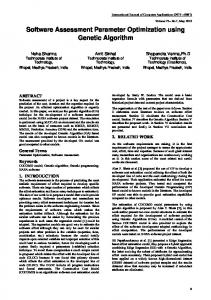
The obtained results are also reported in the 3D graph of Fig. 8, which shows the spalling stress for the different values of the web thickness and the strand eccentricity. It can be observed that for the considered values, the spalling stress is approximately linear. This leads to the possibility to obtain (for the specific HCS) a sensitivity trend of the spalling stress to the strand eccentricity of 0.6 MPa/cm and to the web thickness of 0.20 Mpa/cm.
Spalling stress (MPa)
0
0,5
1
1,5
2
2,5
3
Web axis (cm)
0 5
e = 110 e = 120
10
e = 130
15 20 25 30
Figure 6. Spalling stress along the web height, for a web thickness of 52.5 mm and for different values of the strand eccentricity.
Spalling stress (MPa)
0
0,5
1
1,5
2
2,5
3
Web axis (cm)
0 5
e = 110 e = 120
10
e = 130
15 20 25 30
Figure 7. Spalling stress along the web height, for a web thickness of 62.5 mm and for different values of the strand eccentricity.
Figure 8. Spalling stress for different values of the web thickness and the strand eccentricity.
2.3. Comparison with the prescriptions of European standards In the HCS design, the spalling stress in the webs is regulated by EN 1168+A2 (2010), Art. 4.3.3.2.1 “Resistance to spalling for prestressed hollow core slabs”. The resistance to spalling has to be verified for the web in which the highest spalling stress will be generated, or, for the whole section if the strands or wires are essentially well distributed over the width of the element, the spalling stress σsp shall satisfy the following condition: sp f ct (7) with:
sp
P0 bw e0
15 e2,3 0,007 1, 5
l 1 pt1 1,3 e 0,1 e0
and:
e
(e0 k ) 0 h
(8)
(9)
where: fct is the value of the tensile strength of the concrete deduced at the time that the prestress is released on the basis of tests; Po is the initial prestressing force just after release in the considered web; bw is the thickness of an individual web; eo is the eccentricity of the prestressing steel;
lpt1 is the lower design value of the transmission length; k is the core radius taken equal to the ratio of the section modulus of the bottom fiber and the net area of the cross section (Wb/Ac); The spalling stress has been calculated for all nine different ribs. The spalling stress calculated by means of FEM analyses values are compared with those obtained with the indications provided in EN 1168+A2 (2010) for different web thicknesses (Figs 9-11).
Figure 9. Comparison of the spalling stresses from EN 1168+A2 (2010) and those obtained from the FEM analyses for a web thickness of 42.5 mm.
Figure 10. Comparison of the spalling stresses from EN 1168+A2 (2010) and those obtained from the FEM analyses for a web thickness of 52.5 mm.
Figure 11. Comparison of the spalling stresses from EN 1168+A2 (2010) and those obtained from the FEM analyses for a web thickness of 62.5 mm.
The comparison shows a good fitting between the values obtained by the FEM analyses and those obtained by the EN 1168 standard. However, for lower stress values, the EN 1168 standard provides values almost equal or slightly higher than those obtained by the FEM analyses, a trend that inverts when the stress values come close to limit tensile strength of the concrete. For example, with reference to the case of Fig. 11 (web thickness of 62.5 mm), when the strand is placed 2 cm from the inferior border of the slab, the code check underestimates about 17% the spalling stresses calculated with the numerical method.
3. Optimization of the cross section The slab dimensioning takes place accounting for both stresses due to service loads and those due to the prestressing force transfer. The stresses due to service loads depend on the global behavior of the slab under the vertical service loads, while the tensile stresses during prestressing, are local stresses that have an influence only on the transmission length. In order to take into account the prestressing stresses it is necessary to adopt a refined numerical model of the slab near the support, such as the 3D model implemented in section 2 that accounts for the diffusion of the prestressing forces. The stresses due to service loads on the other hand, can be calculated with simpler numerical models that account for the global behavior of the slab subjected to flexure and shear. Considering the above, in the adopted optimization procedure, two different numerical models have been adopted. A micro-scale model consisting in hexahedral FEM elements as the one described in Section 2, and a meso-scale model obtained by the discretization of the slab with shell elements, using appropriate boundary conditions that account for the translation and reflection symmetries (Fig. 12).
More precisely, the model represents only half of the rib (consisting in one web and the corresponding lower and upper parts of the slab). In order to reproduce the entire rib, reflection symmetry constraints are introduced in the opposed section of the reference system (with origins at the edge of the half rib). In order to reproduce the behavior of the entire slab starting from the single rib, translation symmetry constraints are introduced at flanges along the entire length of the rib. In the meso-scale model, equivalent forces are inserted in correspondence to the slab head for modeling the pre-stress of the cables, while both concrete and steel are considered with linear elastic constitutive relations.
Figure 12. Longitudinal stress in the global numerical model of the as a consequence of both the prestressing and the vertical loads [MPa].
Fig. 13 provides an overview of the five geometric features considered as variables during the automatic sizing of the cross section, while the strand prestressing is considered as a sixth variable. Table 2 provides a description of the variables. These variables are optimized with respect to the total slab weight, accounting for the verification of global and local stress states. Using different values for the geometric features, it is possible to consider hollow core slabs totally different in form and size during the optimization process. Table 2. Description of the considered variables VARIABLE X1 X2 X3 X4 X5 X6
DESCRIPTION Upper flange thickness Web thickness Lower flange thickness Slab height Distance between webs Strand prestressing force
Binary encoding
X1,i X2,i X3,i X4,i X5,i X6,i
01001101 00100110 10010000 00001001 11000100 00100100
Crossover operator
X1,i = 77 mm = 01001101
Old
X1,j = 33 mm = 00100001
01001001 = 73 mm
New 00100101 = 37 mm
Figure 13. The binary genetic code matching the geometry characteristics of the section (above) and example of crossover operation (below).
As stated in Section 1, a GA is an example of a stochastic evolutionary process where an initial random population evolves in order to maximize a fitness function. The GA initiates by considering an initial population of vectors x created assigning random values to the unknown variables. This represents a specific configuration of the problem under consideration. In the case under study for example, each population represents a section with different geometric features. In this sense, the values adopted for the optimization problem variables, characterize a specific solution (individual). These variables, appropriately decoded in binary code, represent the genetic code of the individual. The initial population (representing cross sections of different geometry) is randomly chosen. On the basis of the genetic code of each individual, the global and local structural models are created. The structural analyses are carried out on this model, focusing on the evaluation of the maximum stress levels. The optimization aims to the cross section geometry with the minimum weight, subjected to the check of local and global stresses. The latter constitute the optimization problem constrains. From the genetic code of each individual it is possible to calculate the volume, and thus the weight. In this study the fitness function, the one that measures the quality of the represented solution, is taken as a function of the weight of each individual. From an analytical point of view, the optimization problem is equivalent to the estimation of a minimum of a function F(x) subject to certain constraints gi(x) and hi(x), as shown in Eq. 10.
min F ( x) ai gi ( x) bi i 1...m h ( x) c j 1...k i j
(10)
The fitness function F includes terms to represent the weight of the slab as a function of the slab section geometry. The considered constraints in Eq. 10 are two kind of inequality constraints. First, functions gi(x), representing the geometry constrains. In order to reduce the optimization space close to a meaningful design solution, gi(x) assume the values in the range indicated in Tab. 2. The above constraints are implicitly satisfied during the definition of the variable space within the optimization procedure. Functions hi(x) instead, represent the structural safety constraints. In this study, two checks are carried out. The first one on the bending stress, carried out after the initial structural analyses on the meso-scale model. The second one, on the spalling stress, carried out on the micro-scale model. If both checks are positive, the individual is considered as fitting the constrain conditions, otherwise, it is discarded and a different element is introduced in the population. After the structural analyses it is possible to order all individuals of the population that respect the stress constrains, on the basis of their fitness function. Consequently, by applying different genetic operators (reproduction, crossover, mutation), it is possible to come up with a new population with a generally higher value of the fitness function. Fitness proportionate selection (roulette-wheel selection) is the implemented selection approach. In general, this is a very common selection approach, for which, if there is a big difference between the fitness function of individuals, a weaker individual has lower probability to survive through to the next generation. For this particular case, and considering the specific geometric limitations for the slab, this selection procedure is reliable since the research space is considered limited to solutions already valid from an engineering point of view. This procedure is repeated for an adequate number of cycles, until the population of the individuals reaches a adequately stable reproduction state, that is until a convergence criterion is satisfied. The entire procedure is shown in the flowchart of Fig. 14. As discussed earlier, the six variables considered in the design are transformed in binary code and the string of 0 and 1’s formed in this manner represents the genetic code of a specific individual. During the optimization process, the assumed variables are bounded in the intervals indicated in Table 2. The genetic analyses are performed on a population of 70 individuals that has been regenerated 200 times. The probability variables that govern the crossover and mutation are taken equal respectively to 0.85 and 0.02. Table 3 shows the initial values and those obtained values at the end of the optimization process, while Fig. 15 reproduces the evolution of the cross section during the different population generations. As it can be observed from the results of Table 3, comparing the obtained geometry with the original one from Table 1, the optimization leads to a slightly higher section, with webs placed closer to each other. Both upper and lower flanges are now thinner, while the webs are thicker. Also, the prestressing force is slightly lower. The total weight reduction, compared to the original design, is of approximately 8%. Table 3. Original values and values obtained for the variables after the optimization process. Variable Initial value Value after the optimization Upper flange thickness 30 mm 25 mm Web thickness 42 mm 35 mm Lower flange thickness 30 mm 25 mm Slab height 300 mm 320 mm Distance between webs 425 mm 350 mm Strand prestressing force 116 KN 106 kN
Start
Build initial population Structural analysis: meso-scale model
Spalling stress check
Generation cycle
Structural analysis: micro-scale model
Population cycle
Bending stress check
Fitness evaluation
Selection Reproduction Crossover Mutation
Genetic operators
N cycles
M cycles
End
Figure 14. Flowchart of the optimization process.
Figure 15. Evolution of the cross section during the optimization: (a) initial population; (b) population after 100 regenerations; (c) population after 150 regenerations; (d) best individual.
4. Conclusions This study focuses on the structural design and optimization of geometric and mechanical characteristics of hollow core slabs. The structural behavior of such structures requires the use of different modeling levels for the safety assessment. Indeed, if a meso-scale model is capable of reproducing the bending behavior of the structure at a global level, at a local level, the prestressing stress at the transfer zone can lead to splitting and spalling that may compromise the safety of the entire slab. Considering the above, the spalling crack formation has been investigated in detail, using both three dimensional FEM elements and simplified formulas found in codes and standards. More precisely, the following points are made: The spalling stress value is very sensitive to the web thickness and the strand eccentricity. For the specific cases considered, the vertical tensile stress has a sensitivity trend to the web thickness of 0.20 Mpa/cm and to the strand eccentricity of 0.6 MPa/cm. The assumption of a linear diffusion of the prestressing, usually accepted in codes, leads to an underestimation of the spalling stress of up to 20%. This underestimation is higher for slabs that have a greater strand eccentricity. These points lead to the conclusion that the form optimization of a HCS cannot be implemented by considering the purely shell behavior of the slab and the structural modeling in different scales has to be considered. More precisely, a macro and meso-scale model, capable to swiftly portray the bending characteristics of the slab and a micro-scale model, capable of reproducing the diffusion of the cracks due to the prestressing forces at the slab head. In fact, the optimization was performed by coupling a commercial FEM code, able to represent the meso-scale model, and a numerical model in FORTRAN, able to represent the micro-scale model and to conduct the genetic optimization. With this in mind, it is important to point out the way an optimization process can envisage different models of the same structure, each one of which optimized for a particular aspect of the structural behavior.
Acknowledgements The authors would like to thank Prof. Pier Giorgio Malerba of the Politecnico di Milano, for fruitful discussions and valuable suggestions. Furthermore, the authors would like to thank the anonymous reviewers for their helpful and constructive comments that greatly contributed to improving this paper. This work was partially supported by StroNGER s.r.l. from the fund “FILAS - POR FESR LAZIO 2007/2013 - Support for the research spin-off”. References Adeli, H. and Kumar, S. (1995), “Concurrent Structural Optimization on a Massively Parallel Supercomputer”. J. Struct. Eng.- ASCE, 121(11), 1588-1597. Adeli, H. and Park, H.S. (1995), “Optimization of space structures by neural dynamics”, Neural Networks, 8(5), 769-781. Adeli, H. and Samant, A. (2000), “An adaptive conjugate gradient neural network—wavelet model for traffic incident detection”, Comput-Aided Civ. Inf., 15(4), 251–260. Al-Bazi, A. and Dawood, N. (2010), “Developing Crew Allocation System for Precast Industry Using Genetic
Algorithms”, Comput-Aided Civ. Inf., 25(8), 581-595. Amir, O. (2013), “A topology optimization procedure for reinforced concrete structures”, Comput. Struct., 114-115, 46-58. Arangio, S. and Beck, J. L. (2011), Bayesian neural networks for bridge integrity assessment, Struct. Control Hlth., 19(1), 3-21. Arangio, S. and Bontempi, F. (2010), Soft Computing Based Multilevel Strategy for Bridge Integrity Monitoring, Comput-Aided Civ. Inf., 25(5), 348–362. Araujo, C.A.M., Loriggio, D.D. and Da Camara, J.M.N.N. (2011), Anchorage failure and shear design of hollow-core slabs, Struct. Concrete, 12(2), 109-119. Baitsch, M. and Hartmann, D. (2006), Optimization of slender structures considering geometrical imperfections, Inverse Probl. Sci. Eng., 14(6), 623–637. Bel Hadj Ali, N., Rhode-Barbarigos, L., Pascual Albi, A.A. and Smith, I.F.C. (2010), “Design optimization and dynamic analysis of a tensegrity-based footbridge”, Eng. Struct., 30(11), 3650-3659. Benítez, J. M., Gálvez, J. C. (2011), “Bond modelling of prestressed concrete during the prestressing force release”, Mater. Struct., 44(1), 263-278. Biondini, F., Bontempi, F. and Malerba, P.G. (2004a), Fuzzy reliability analysis of concrete structures, Comput. Struct., 82(13-14), 1033-1052. Biondini, F., Bontempi, F., Frangopol, D.M. and Malerba P. G. (2004b), “Reliability of material and geometrically non-linear reinforced and prestressed structures”, Comput. Struct., 82(13-14), 1021-1031. Bocchini, P. and Frangopol, D.M. (2011), “A probabilistic computational framework for bridge network optimal maintenance scheduling”, Reliab. Eng. Syst. Safe., 96(2), 332–349. Bogomolny, M. and Amir, O. (2012), “Conceptual design of reinforced concrete structures using topology optimization with elastoplastic material modeling”, Int. J. Numer. Meth. Engng, 90(13),1578-1597. Bontempi, F., Biondini, F. and Malerba, P.G. (2000), “The search for structural schemes by using optimality criteria and soft computing techniques”, in: Proceedings of Structural Morphology Conference, August 1719, Delft, The Netherlands. Bontempi, F., Gkoumas, K. and Arangio, S. (2008), “Systemic approach for the maintenance of complex structural systems”, Struct. Infrastruct. E., 4(2), 77-94. Bontempi, F. and Malerba, P. G. (1997), “The role of softening in the numerical analysis of R.C. framed structures”, Struct. Eng. Mech., 5(6), 785-801. Boto-Giralda, D., Díaz-Pernas, F.J, González-Ortega, D., Díez-Higuera, J.F., Antón-Rodríguez, M. and Martínez-Zarzuela, M. (2010), “Wavelet-Based Denoising for Traffic Volume Time Series Forecasting with Self-Organizing Neural Networks”, Comput-Aided Civ. Inf., 25(7), 530-545 Buettner, D.R., and Becker, R.J. (1998), Manual for the Design of Hollow Core Slabs, (2nd Edition), Precast/Prestressed Concrete Institute, Chicago, IL. Capuano, G., Della Bella, B., Della Bella, G., Ghittoni, P., Morandi, P. and Nilson, C. (2002), The hollow core floor. Design and applications, (1st edition), Manual ASSAP, Verona. Italy. Ceravolo, R., De Stefano, A. and Sabia, D. (1995), “Hierarchical use of neural techniques in structural damage recognition”, Smart Mater. Struct, 4(4), 270-280. Chang, J., Buchanan, A.H., Dhakal, R.P. and Moss, P.J. (2008), “Hollow-core concrete slabs exposed to fire”, Fire Mater., 32(6), 321–331. Cheng, J. (2007), “Hybrid genetic algorithms for structural reliability analysis”, Comput. Struct., 85(19-20), 1524-1533. Collins, M. P., and Mitchell, D. (1980), “Shear and Torsion Design of Prestressed and Non-Prestressed Concrete Beams” PCI J., 25(5), 32-100. Cuenca, E., Serna, P. (2013), Failure modes and shear design of prestressed hollow core slabs made of fiberreinforced concrete, Compos Part B-Eng., 45(1), 952-964. de Albuquerque, A. T., El Debs, M. K. and Melo, A. M. C. (2012), “A cost optimization-based design of precast concrete floors using genetic algorithms”, Automat Constr., 22, 348–356. de Castilho, V. C., El Debs, M. K. and Nicoletti, M. do C. (2007), “Using a modified genetic algorithm to minimize the production costs for slabs of precast prestressed concrete joists”, Eng. Appl. Artif. Intel., 20(4),
519-530. de Castilho, V. C., Nicoletti, M. do C. and El Debs, M. K. (2005), “An investigation of the use of three selection-based genetic algorithm families when minimizing the production cost of hollow core slabs”, Comput. Method. Appl. M., 194(45-47), 4651-4667. del Coz Díaz, J.J., García Nieto, P.J., Álvarez Rabanal, F.P., Martínez-Luengas, A.L. (2011), “Design and shape optimization of a new type of hollow concrete masonry block using the finite element method”, Eng. Struc., 33(1), 1-9. Deng, L. and Cai, C.S. (2009), “Identification of parameters of vehicles moving on bridges”, Eng. Struct., 31(10), 2474-2485. Descamps, B., Coelho, R.F., Ney, L. and Bouillard, Ph. (2011), “Multicriteria optimization of lightweight bridge structures with a constrained force density method”, Comput. Struct., 89(3-4), 277–284. De Stefano, A., Sabia, D. and Sabia, L. (1999), “Probabilistic neural networks for seismic damage mechanisms prediction”, Earthq. Eng. Struc., 28(8), 807–821. Dordoni, S., Malerba, P.G., Sgambi, L. and Manenti, S. (2010), “Fuzzy reliability assessment of bridge piers in presence of scouring”, in: Proceedings of The Fifth Int. Conf. on Bridge Maintenance, Safety and Management (IABMAS’10), July 11-15, Philadelphia (USA). Elgabbas, F., El-Ghandour, A. A., Abdelrahman , A. A. and El-Dieb, A. S. (2010), “Different CFRP strengthening techniques for prestressed hollow core concrete slabs: Experimental study and analytical investigation”, Compos. Struct., 92(2), 401–411. EN 1168+A2 (2010), Precast concrete products. Hollow core slabs. EN 1992-1-1. Eurocode 2—design of concrete structures. 2004. Fairbairn, E. M. R., Silvoso, M. M., Toledo Filho, R. D. , Alves, J. L. D. and Ebecken, N. F. F. (2004), “Optimization of mass concrete construction using genetic algorithms”, Comput. Struct., 82(2-3), 281-299. Foster, S. J., Budiono, B. and Gilbert, R. I. (1996), “Rotating crack finite element model for reinforced concrete structures”, Comput. Struct., 58(1), 43-50. Gálvez, J. C., Benítez, J. M., Tork, B., Casati, M. J., Cendón, D. A. (2009), “Splitting failure of precast prestressed concrete during the release of the prestressing force”, Eng. Fail. Anal., 16(8), 2618-2634. Garavaglia, E., Pizzigoni, A., Sgambi, L., Basso, N. (2013), “Collapse behaviour in reciprocal frame structures”, Struct. Eng. Mech., 46(4), 533-547. Gaudenzi, P., Fantini, E., Koumousis, V.K. and Gantes, C.J. (1998), “Genetic Algorithm Optimization for the Active Control of a Beam by Means of PZT Actuators”, J. Intel. Mat. Syst. Str., 9(4), 291-300. Girhammar, U. A. and Pajari, M. (2008), “Tests and analysis on shear strength of composite slabs of hollow core units and concrete topping”, Constr. Build. Mater., 22(8), 1708–1722. Giuliani, L. (2012), “Structural safety in case of extreme actions”, Special Issue on: "Performance and Robustness of Complex Structural Systems", Guest Editor Franco Bontempi, Int. J. Life Cycle Perf. Eng. (IJLCPE), in press (ISSN: 2043-8648). Graf, W., Freitag, S., Kaliske, M. and Sickert, J.U. (2010), Recurrent neural networks for uncertain timedependent structural behavior, Comput-Aided Civ. Inf., 25(5), 322-333. Guan, H. (2005), “Strut-and-tie model of deep beams with web openings- An optimization approach”, Struct. Eng. Mech., 19(4), 361-380. Hegger, J., Roggendorf , T., Kerkeni, N. (2009), “Shear capacity of prestressed hollow core slabs in slim floor constructions”, Eng. Struct., 31(2), 551-559. Hsu, T.T.C. (1988), “Softened Truss Model Theory for Shear and Torsion”, ACI Struct. J., 85(6), 624-635 Jafarkhani, R. and Masri, S.F. (2011), “Finite Element Model Updating Using Evolutionary Strategy for Damage Detection”, Comput-Aided Civ. Inf., 26(3), 207-224. Jiang, X. and Adeli, H. (2005), “Dynamic wavelet neural network for nonlinear identification of highrise buildings”, Comput-Aided Civ. Inf., 20(5), 316–330. Kim, Y., Langari, R. and Hurlebus, S. (2010), “Model-based Multi-input, Multi-output Supervisory Semiactive Nonlinear Fuzzy Controller”, Comput-Aided Civ. Inf., 25(5), 387-393. Kim, S.H., Yoon, C. and Kim, B.J. (2000), “Structural monitoring system based on sensitivity analysis and a neural network”, Comput-Aided Civ. Inf., 15(4), 309–318.
Koh, B.H. and Dyke, S.J. (2007), “Structural health monitoring for flexible bridge structures using correlation and sensitivity of modal data”, Comput. Struct., 85(3-4), 117–130. Lam, D. (2002), “Composite steel beams with precast hollow core slabs: behaviour and design”, Prog. Struct. Eng. Mater., 4(2), 179-185. Lam, D., Elliott, K. S., Nethercot, D. A. (2000), “Parametric study on composite steel beams with precast concrete hollow core floor slabs”, J. Constr. Steel Res., 54(2), 283-304. Lee,Y. and Wei, C.H. (2010), “A Computerized Feature Selection Using Genetic Algorithms to Forecast Freeway Accident Duration Times”, Comput-Aided Civ. Inf., 25(2), 132-148. Liu, W., Gao, W-c., Sun, Y. and Xu, M-j. (2008), “Optimal sensor placement for spatial lattice structure based on genetic algorithms”, J. Sound Vib., 317(1-2), 175–189. Luo, Y. and Kang, Z. (2013), “Layout design of reinforced concrete structures using two-material topology optimization with Drucker–Prager yield constraints”, Struct. Multidiscip. O., 47( 1), 95-110 Malekly, H., Mousavi, S.M. and Hashemi, H. (2009), “A fuzzy integrated methodology for evaluating conceptual bridge design”, Expert Syst. Appl., 37(7), 4910-4920. Mathakari, S., Gardoni, P., Agarwal, P., Raich, A. and Haukaas, T. (2007), “Reliability-based Optimal Design of Electrical Transmission Towers Using Multi-objective Genetic Algorithms”, Comput-Aided Civ. Inf., 22(4), 282-292. Möller, B., Graf, W. and Beer, M. (2003), “Safety assessment of structures in view of fuzzy randomness”, Comput. Struct., 81(15), 1567-1582. Orcesi, A.D. and Frangopol, D.M. (2011), “Optimization of bridge maintenance strategies based on structural health monitoring information”, Struct. Saf., 33(1), 26–41. Pang X.B.D. and Hsu T.T.C. (1995), “Behaviour of reinforced concrete membrane elements in shear”, ACI Struct. J., 92(6), 665-679. Petrini, F. & Bontempi, F. (2011), “Estimation of fatigue life for long span suspension bridge hangers under wind action and train transit”, Struct. Infrastruct. E., 7(7-8), 491-507. Petrini F., Li H. and Bontempi F. (2010), “Basis of Design and Numerical Modeling of Offshore Wind Turbines”, Struct. Eng. Mech., 36(5), 599-624. Pisanty, A. (1992), “The shear strength of extruded hollow-core slabs”, Mater. Struct., 25(4), 224-230. Pisanty, A. and Regan, P. E. (1991), “Direct assessment of the tensile strength of the web in prestressed precast hollow-core slabs”, Mater. Struct., 24(6), 451-455. Przemieniecki, J.S. (1968), Theory of Matrix Structural Analysis, New York: McGraw-Hill. Reuter, U. and Möller, B. (2010), “Artificial Neural Networks for Forecasting of Fuzzy Time Series”, ComputAided Civ. Inf., 25(5), 363-374. Rohani, S.M., Vafaeesefat, A., Esmkhani, M., Partovi, M. and Molladavoudi, H.R. (2013), “Composite locomotive frontend analysis and optimization using genetic algorithm”, Struct. Eng. Mech., 47(5), 729740. Sadeghi, N., Fayek, A.R. and Pedrycz, W. (2010), “Fuzzy Monte Carlo Simulation and Risk Assessment in Construction”, Comput-Aided Civ. Inf., 25(4), 238-252. Sgambi, L. (2004), “Fuzzy theory based approach for three-dimensional nonlinear analysis of reinforced concrete two-blade bridge piers”, Comput. Struct., 82(13-14), 1067-1076. Sgambi, L. (2008), “Artificial Intelligence: Historical Development and Applications in Civil Engineering Field”, in: Proceedings of The Fourth Int. Conf. on Bridge Maintenance, Safety and Management (IABMAS’08), July 13-17, Seoul (Korea), ISBN 978 0 415 46844 2. Sgambi, L., Gkoumas, K. and Bontempi, F. (2012), “Genetic Algorithms for the Dependability Assurance in the Design of a Long-Span Suspension Bridge”, Comput-Aided Civ. Inf., 27(9), 655–675. Srinivas, V. and Ramanjaneyulu, K. (2007), “An integrated approach for optimum design of bridge decks using genetic algorithms and artificial neural networks”, Adv. Eng. Softw., 38(7), 475-487. Starossek, U. and Haberland, M. (2011), “Approaches to measures of structural robustness”, Struct. Infrastruct. E., 7(7-8), 625-631 Tagherouit, W.B., Bengassem, J. and Bennis, S. (2011), “A Fuzzy Expert System for Prioritizing Rehabilitation Sewer Networks”, Comput-Aided Civ. Inf., 26(2), 146-152.
Tomás, A. and Martí, P. (2010), “Shape and size optimisation of concrete shells”, Eng. Struct., 32(6), 16501658. Vecchio F.J. and Collins M.P. (1986), “The modified compression field theory for reinforced concrete elements subjected to shear”, J. Am. Concrete I., 83(2), 219-231. Vlahogianni, E.I., Karlaftis, M.G. and Golias, J.C. (2007), “Spatio-Temporal Short-Term Urban Traffic Flow Forecasting Using Genetically-Optimized Modular Networks”, Comput-Aided Civ. Inf., 22(5), 317-325. Wang, K.C.P. and Li, Q. (2011), “Pavement Smoothness Prediction based on Fuzzy and Gray Theories”, Comput-Aided Civ. Inf., 26(1), 69-76. Wilson, J.L., Robinson, A.J., Balendra, T. (2008), “Performance of precast concrete load-bearing panel structures in regions of low to moderate seismicity”, Eng. Struct., 30(7), 1831-1841. Zadeh, L.A. (1965), “Fuzzy sets”, Inform. Control, 8(3), 338-353. Zadeh, L. (1997), “What is Soft Computing”, Soft Comput., 1(1), 1.