Geospatial Databases and Augmented Reality Visualization for Improving Safety in Urban Excavation Operations Sanat A. Talmaki1, Suyang Dong2, Vineet R. Kamat3 Graduate Student Research Assistant, University of Michigan,
[email protected], 2 Graduate Student Research Assistant, University of Michigan,
[email protected] 3 Associate Professor, University of Michigan,
[email protected] Department of Civil and Environmental Engineering, 2350 Hayward Street, Room 2340 GGB, Ann Arbor, Michigan 48109-2125, USA 1
Subject Areas: Automated/Real-Time Systems Information Technology and Computer Applications Abstract: The U.S. has more than 14 million miles of buried pipelines and utilities, many of which are in congested urban environments where several lines share the underground space. Errors in locating excavations for new installation or for repair/rehabilitation of existing utilities can result in significant costs, delays, loss of life, and damage to property (Sterling 2000). There is thus a clear need for new solutions to accurately locate buried infrastructure and improve excavation safety. This paper presents ongoing research being collaboratively conducted by the University of Michigan and DTE Energy (Michigan’s largest electric and gas utility company) that is investigating the use of Real-Time Kinematic GPS, combined with Geospatial Databases of subsurface utilities to design a new visual excavator-utility collision avoidance technology. 3D models of buried utilities are created from available geospatial data, and then superimposed over an excavator’s work space using geo-referenced Augmented Reality (AR) to provide the operator and the spotter(s) with visual information on the location and type of utilities that exist in the excavator’s vicinity. This paper describes the overall methodology and the first results of the research.
1. Introduction: The underground space in urban environments is a spider’s web of electric lines, gas lines, cable TV lines, fiber optics, telephone cables, traffic signals, street lighting circuits, drainage and flood control facilities, water mains and waste water pipes. In some locations, major oil and gas pipelines, national defense communication lines and mass transit rail/road tunnels, all compete for place underground (Sterling 2000). The U.S. has more than 14 million miles of buried pipelines and utilities, many of which are in congested urban environments where several lines share the underground space. Hits to utility lines cause interruption to daily life and commerce, and physical danger to workers, bystanders and nearby buildings. These costs are borne by the Contractor, Locating Company, Utility Providers, Insurance Companies, Affected Public and Business Owners. Thus it is a cost borne by all parties, including tax payers and society at large either directly or indirectly. The period from 2004 to 2007 saw a total of 52 fatalities, 132 injuries and over 600 million dollars loss in damage to property. Additionally, of all incidents related to buried utilities, excavation related accidents accounted for nearly one-third (PHMSA 2009). Thus it is apparent that increased attention needs to be paid to utility locating technologies that aid in accurate and safe excavation. A Federal study on buried utility detection technology identified the following two goals: firstly, avoiding third-party damage to existing underground utilities that is caused by the presence of unknown or mislocated utilities; and secondly, developing utility location capabilities independent of size, depth and utility materials, that can detect even in presence of utility congestion.
1
The overarching goal of our ongoing research project is to address this critical state of affairs and propose new integrated technological solutions to prevent excavator-utility hits, and thereby improve safety and accuracy in urban excavation projects. 2. Problem Description: Locating underground pipes and other infrastructure prior to excavation has long been a problem area due to complexity involved and the large number of variables over which accurate control is not possible. This section deals with the current state of affairs in terms of locating utility lines and limitations in them. 2.1 Current Locating Technologies: Geophysical technologies are those technologies that assist in investigating the earth’s sub-surface. While tremendous development has taken place in the field of locating technologies over the past decade, no one method has emerged as being complete and without flaws. The following is a brief description of the most commonly used methods in locating underground utilities. Ground Penetrating Radar (GPR): Ground Penetrating Radar (also known as Ground Probing Radar) is a technique that uses short duration, high frequency electromagnetic wave pulses. These pulses are transmitted from an antenna into the ground. Materials such as rocks, water, or pipes buried below the surface reflect the waves which are returned as an echo. While GPR is widely used with good results, when used with conductive soils (clays, saturated soils, etc.) and in congested environments (presence of rocks etc), it gives below par results. (Read and Vickridge 1997) Electromagnetic Techniques: Electromagnetic methods detect the field generated by the buried network and not the buried pipe itself. Electromagnetic techniques can be Active or Passive. Active systems depend on current being applied to the pipe and detecting the field thus generated. While in passive systems, the location is based on receiving natural signals transmitted from the underground assets themselves as would be the case of an electric conduit that has current flowing through it naturally. Electromagnetic methods are low cost, simple and quick but cannot locate non-metallic pipes except if tracer wires or Sondes are used (Read and Vickridge 1997). Magnetometer Technique: This method works on the fact that the earth’s magnetic field varies over a particular distance which is caused by underground features such as metallic pipes, large voids and ore bodies. The setup uses two coils to evaluate the difference in intensity and/or direction of the vertical component of magnetic flux which maybe caused by a ferromagnetic object. The advantage of this method is that it is relatively cheap. However, presence of buildings, cables, fences, etc affect the output considerably and thus this method cannot be relied upon entirely (Read and Vickridge 1997). Resistivity Methods: The setup for this method uses 4 electrode probes placed in a line in the ground and a current passed through the outer pair. The inner pair measures the potential drop between them, giving an estimate of ground resistivity. However this method is quite slow. The electrodes need to be coupled very well with the ground making surveying beneath roads for buried assets difficult (Read and Vickridge 1997).
2
Acoustic Detection Systems: Although acoustic detection methods are primarily used for locating leaks in water mains, they can also be employed for detecting and mapping water distribution pipe networks. However the system requires easy access to the pipelines like a hydrant or a water meter. Passing traffic can also lead to sources of errors. Thus it is limited to small and shallow networks. No depth value can be obtained as well. (Read and Vickridge 1997) Infrared Thermography: This method is based on measuring very slight variations in temperature, and producing a thermographic image, where objects are represented by their thermal rather than their optical values. An infra-red scanner head and detector are used to capture the thermal data. The equipment is relatively expensive. Ground moisture content drastically affects the readings and depth values cannot be measured. Thus it needs a supplementary system to measure depth values (Read and Vickridge 1997) Subsurface Utility Tracing: In this method a signal is induced in a subsurface utility and the signal’s position is tracked as it moves along the utility. It is also referred to as Direct Induced Signal Emission as the electric field formed as a result of the signal passed is used to detect the buried pipe. Vacuum Extraction: Another method often used is Vacuum Extraction (Vacuum Excavation) or Potholing. This method offers the option of safely and economically excavating in areas inaccessible to conventional digging equipment. The air excavation method however cannot be used on hard surfaces like pavements and has a higher initial cost. The water vacuum excavation systems can cut pipes or electrical conduits due to the force of the water (Read and Vickridge 1997). Each of the described techniques is effective in certain scenarios and less effective in others. However given the wide range of variables that one has to deal with in underground utility location, no single technology emerges as being comprehensive in locating underground utilities of all types in a range of soil conditions. Thus it is generally accepted in the industry that a multi-sensory approach that would utilize a combination of such technologies is likely to give more accurate results. 2.2 One-Call Utility Notification Organizations: A study of various One-Call Utility pre-marking systems/organizations reveal that most states within USA require by law for excavators to have the utilities pre-marked by the identification service before actual excavation is carried out. Michigan's statute, Act 53 of Public Act 1974, requires anyone who engages in or is responsible for the planning or performance of any type of excavation e.g.; grading, demolition, cultivating, auguring, blasting, or boring to provide advance notice of at least three full working days to MISS DIG (MISS DIG Systems Inc. 2009). In the state of Michigan, MISS DIG SYSTEMS is the One-Call Utility Notification Organization. The MISS DIG system and other similar One-Call systems have reduced utility line hits to a great extent. However such systems still have 2 limitations in their current form (DTE Energy 2009, Personal Communication). The first being that location of a buried utility is marked approximately on the surface within a 3 feet wide band rather than its exact location, and once the excavator has removed the top
3
soil/surface, the operator once again depends more on judgment than on visible information. Secondly, MISS DIG system does not provide any information regarding depth of a buried utility (MISS DIG Systems Inc 2009). Furthermore, as noted above, the markings are made as a strip of potential area which is 18 inches wide on either side of the utility line’s expected location. This equates to a zone that is 3 feet wide. Thus it is not as exact as an excavator operator would like and current One-Call systems would need additional improvements to make them more useful for excavators. 2.3 As Built versus Actual: The single largest cause for utility line hits is the discrepancy between as-built drawings and actual location of utility lines and incomplete as-built drawings (Hammond and Weintraut 2001). This issue leads to negating the positive effect of the MISS DIG System. Most utility owners including our collaborator DTE Energy concede that often times the as-built drawings show a completely different picture from what actually exists beneath (DTE Energy 2009, Personal Communication). Part of the problem lies in the method of laying utility lines. In extremely crowded urban environments, contractors are left with no choice but to shift utility alignments by a few inches to a few feet to account for existing utility lines occupying the same space. AsBuilt drawings thus do not actually represent the reality of what lies beneath (Hill 2006). Since existing As-Built data solely does not accurately serve the purpose of underground utility locations, an alternate method of location, based on a combination of recorded asbuilt data, and active real-time sensing is proposed in the following section. 3. Importance of the Research: The importance of research in the area of underground utility location can be exemplified by incidents of stray hits to utility lines that look innocuous at first but have consequences that are dire. An example of such a hit was a case in January 1995 when a construction crew driving piles for a new garage accidently crushed a high voltage underground electric cable serving Newark International Airport’s three passenger terminals. As a result, hundreds of flights were cancelled and thousands of passengers were left stranded (Minneapolis Star Tribune 1995). Also with utility companies spending millions of dollars every year on locating their buried assets and accident recovery (Sterling 2000), it is clear that the area is in need of urgent attention. 3.1 Federal Interest in Utility Locating Technologies: A Federal Study on Utility Locating Technologies suggested that that multi-sensor technology (GPR, Acoustic plus Electromagnetic) and multi-frequency approaches offer the greatest potential for standalone utility location in the future (Sterling 2000). The use of this multi-sensor technology together with a 3D model view of the buried infrastructure is one of the responses to the Statement of Need. The view would be of such quality so as to allow identification of material of pipe and other essential details. Section 15 of the Pipeline Safety Improvement Act of 2002 discusses the National Pipeline Mapping System which requires operators of pipeline facilities to provide to the Secretary of Transportation geospatial data appropriate for use in the National Mapping System, the name and address of the person with primary operational control, and a means for a member of the public to contact the operator for additional information about the facilities. There is a requirement to update the information as necessary. Such information can then be used by a system to create 3D models of the buried pipes and be projected onto the real world
4
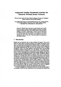
view. Thus there is all-round effort, guided by a federal agenda, to convert buried utility data into a format that is interoperable, accessible, and always current. 3.2 Introduction to the Proposed Collision Avoidance Framework: It is evident that all the existing techniques in the field of underground utility detection have limitations. A consequence of these limitations is the hits to underground utility lines that lead to large values of loss to surrounding facilities, residents and other utilities in the network. Thus an approach that combines these existing technologies by building upon their capabilities offers the most promise to help mitigate the extent of the accidental damage caused. In particular, a technology that gives the excavator the location of the pipes at all times (i.e. even after the top surface has been excavated away) as well as the depth and other attribute information of the pipes can help alleviate most of the problems not addressed by using current technologies. To achieve this, our proposed approach involves the creation of 3D models of the buried pipes from existing databases owned by utility companies and superimposing these models over the normal real-world view (captured in Real Time) of an excavator or backhoe operator using Augmented Reality (AR). This can be better understood by referring to the Figure 1 below.
Figure 1: Data Flow for Collision Avoidance System Using Augmented Reality The advantage of such a technology over using spray paint, stakes or flags to mark the approximate location of the utility is that unlike the existing methods, the location indicators remain in the operator’s view even after the top layer has been excavated away. Furthermore, the superimposed 3D pipe models can be color coded allowing the operator to easily identify the pipe(s) the crew is interested in. As can be seen in Figure 1 above, other attribute information such as depth, material of pipes, etc. can be annotated over the pipes thus giving the excavator additional information. The following section describes our Technical Approach in detail. 4. Technical Approach: The excavator-utility collision avoidance framework being developed by our group is based on the use of Augmented Reality (AR) visualization technology. Data on the underground pipes is obtained from the databases of utility 5
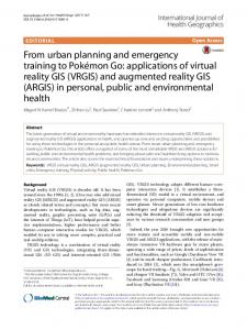
companies. The data from these databases can be transported and encoded in an XML based format called Geography Markup Language (GML). A combination of GML and wireless fidelity make such an operation of transporting data over the internet extremely feasible today unlike a few years ago. Such a view of 3D pipe models on the real world view of a user has been attempted in the past (e.g., Mendez et al. 2008). Utility information has also been visualized as vector based graphics in AR before (e.g., Roberts et al. 2002). In each of these cases, the goal of the study has been to demonstrate the feasibility of AR technology to visualize GIS information. This research builds upon the success of these prior studies and incorporates AR visualization as a key component into a multi-sensory excavator-utility collision avoidance framework. Figure 2 graphically depicts the major components of the developed framework. The major components of the framework are: 1) Accessibility and conversion of accurate asbuilt graphical information on buried utilities; 2) Visualization of annotated graphical information in excavator operator’s view in georeferenced AR; 3) Real-time tracking of excavator’s kinematic articulation and position of digging implement; 4) Proximity querying and interference detection between digging implement’s current location and buried utilities; and 5) Rapid reality capture of buried utilities using geophysical technologies to supplement accuracy achieved by geometric interference analysis. Real World Data Stream
AR Visulization
Geometric Model
Rover Part of RTK Position of Excavator
Video Camera
Electronic Compass
Orientation of Excavator
Tracking and Video Hardware
AR Cabin Platform
GeoDatabase
Figure 2: The architecture of visual excavator-utility collision avoidance framework 4.1 Underground Utility Data Classification: The research team has first begun addressing challenges in the utility data accessibility and conversion component of the proposed framework. We have classified the data into 4 cases such that every owner of utilities whether public or private would fit into one of these 4 cases. A flowchart of this classification is shown in Figure 3.
6
Figure 3: Buried infrastructure data classification cases 1- 4. Case 1 is the best case scenario where utility owners have all their assets stored in a GIS database. Case 2 refers to those owners who have the asset information stored in the form of maps and drawings either in paper or digital form but not in the form of an intelligent database. These maps then need to be converted into GIS format from which a database can be built. When utility owners already have pipes buried underground but are unsure about their exact location, it is classified as Case 3 in our classification. This case will require the use of Geophysical Technologies to get the exact location of the underground utilities. After the location is obtained, a database would be constructed using the geophysical test results. These steps would then bring the data up to the level of Case 1. Case 4 refers to the case when new pipes need to be laid and thus along with documenting the location of pipelines, the use of new technologies such as Radio Frequency Identification (RFID) tags and Sensors mounted on pipes is also envisaged. Thus Case 4 is the all encompassing case. The eventual goal for any case is to produce 3D models of the underground pipes and project them in AR (framework component 2). As a test case, our group worked on a sample dataset provided to us by the University of Michigan Architecture, Engineering & Construction (AEC) division. The data provided to us was in the form of a digital AutoCAD drawing (.dwg file). Thus it was a Case 2 classification. We performed a series of operations to convert this AutoCAD drawing into a GIS shapefile. Our group used ArcGIS 9.3 for this initial test case. The ESRI Shapefile or simply a Shapefile is a popular geospatial vector data format for geographic information systems software. It is developed and regulated by ESRI as a (mostly) open specification for data interoperability among ESRI and other software products. We created 3D models of the pipes in Google SketchUp. Even though this algorithm involved several manual steps, our overall goal is to create 3D models for AR visualization in realtime. Figure 4 below shows the conversion of data from the initial AutoCAD drawing to a Google SketchUp 3D model. The middle drawing has selected utility lines highlighted in red as a feature of being converted into GIS shapefile unlike an AutoCAD drawing.
7
Started with simple CAD drawings
Convert to GIS Shapefiles
Create 3D models in Google Sketchup
Figure 4: Conversion of data from one format to the other. 4.2 Augmented Reality (AR): As Figure 1 shows, to implement the AR view of pipelines on the excavation site, two data resources are needed: the pipeline GIS data and the real world data. The two data resources are retrieved independently and integrated by AR software in real time to render the augmented view. Many local utility companies establish Geodatabases (GIS Databases) for their underground assets. The GIS data is transported via GML. In the GML schema, geographical coordinates, geometric characteristics and other attribute information of the pipelines are represented. At the same time, the real world data contains the real time tracking data and video stream of the real excavation scene. The tracking data supplies the AR system with position and orientation of backhoe, which is used for establishing the camera reference coordinate system with the origin at the video camera. The CAD models of pipelines, which are originally represented under the geographical coordinate system, can thus be aligned with the new camera reference system, calibrated and superimposed on the video sequence representing the real world. 4.3 Working of the System: The framework is based on the data flow chart in Figure 2, . Mounted on the rear of the backhoe is the rover component of a RTK (Real Time Kinematic) GPS system, which transmits the geographical coordinate at the frequency of 1Hz. Considering the chassis of backhoe is stationary at a short time slot during operation, The frequency of 1Hz is enough for updating the position of backhoe. Also the electronic compass is attached to the front of the backhoe close to the boom, and transmits the orientation of boom in the form of yaw, pitch and roll with the maximum sampling speed of 30 times per second. Since the boom of backhoe swinging continuously during excavation, high frequency of orientation sampling is necessary for updating the gaze direction of video camera so as to maintain the correctness of the
8
viewing frustum (Khoury and Kamat 2009). Video stream captured by video camera is put at the background of the augmented view. Eventually, the mixed view of pipelines and real excavation site can be displayed to the excavator operator through a cabin monitor. A prototype simulation of such a system was created in the virtual environment of Google Earth. This prototype simulation is shown in Figure 5 below. Figure 5.a shows the third-person view of the excavation site. Figure 5.b is the augmented view which is displayed on the cabin monitor. Straight colored lines indicate the location of underground utilities, the strip buffer warns the excavator of the uncertainty in the location displayed. The pop-up annotations let the excavator be aware of the attribute information of the buried pipelines.
Figure 5: Interface for the collision avoidance augmented reality system 5. Conclusions and Future Research: The framework described in this paper, by building upon the existing technologies has the potential to transform underground utility locating methods. The simulation in the virtual world of Google Earth shows that having the utility lines pre-marked using AR would be an extremely useful aid to excavators. As mentioned above, the registration process of superimposing pipeline models on the real scene can be divided into two steps: First using the location and orientation of the backhoe to set up the camera reference system; second aligning the pipeline’s geographic coordinate with the camera reference system. Therefore obtaining the accurate location of the excavator and the pipelines are the deciding elements for the registration accuracy. The American Society of Civil Engineers (ASCE) estimates that a total of nearly $2.2 trillion is needed to overhaul the entire United States infrastructure over the next several years. Water and waste water pipelines were given a grade D- in the 2009 ASCE report (ASCE 2009). Laying new pipelines and replacing decades old sewer lines would all be required as part of the expected rehabilitation work. The presented research is thus very timely and critical, as the proposed framework would allow excavating teams to observe buried utilities while on the surface, and could help reduce time and cost over-runs while significantly improving safety. As noted earlier, viewing 3D models of pipes in AR is an initial step of our research. Our eventual goals are to develop an integrated collision avoidance system and a comprehensive utility maintenance system. Ongoing research is addressing technical challenges defined by this overall technical agenda. 9
6. Acknowledgments: The presented work is partially supported by the National Science Foundation (NSF) through grants CMMI-0448762 and CMMI-0825818. The authors gratefully acknowledge NSF's support. The authors thank Mr. Ronnie May, Mr. William Terrasi, Mr. James DeKimpe, Mr. John Squires, and Mr. Steven Facine from DTE Energy for their enthusiastic ongoing collaboration in this project. The authors are also grateful to Mr. Dharmesh Joshi from UM AEC for providing datasets used in the initial experiments of this research. Any opinions, findings, conclusions, and recommendations expressed in this paper are those of the authors and do not necessarily reflect the views of the NSF or the individuals mentioned here. References: ASCE Infrastructure Report Card. (2009), http://www.infrastructurereportcard.org/ Common Ground Alliance. (2009, Feburary), http://www.commongroundalliance.com, Retrieved from Common Ground Alliance: http://www.commongroundalliance.com/Content/NavigationMenu/Best_Practices/Best_Pract ices_2009/BestPractices_6.0_Final_February2009.pdf Cox, S., Daisey P., Lake R., Portele C., Whiteside A. (2002), “OpenGIS Geography Markup Language (GML) Encoding Specification”. Ergen. E., Akinci, B. Sacks, R. (2006), “Tracking and Locating Components in a Precast Storage Yard Utilizing Radio Frequency Identification Technology and GPS”, Automation in Construction, 16(3), 354-367. Hammond, R., Weintraut, J. (2001), “Cleaning Up Indianapolis’ Sewer Layers: When Bad Data Happens to Good People”, http://proceedings.esri.com/library/userconf/proc01/professional/papers/pap425/p425.htm Hill, Walter. G., (2006), “Pipeline and Gas Journal”, http://findarticles.com/p/articles/mi_m3251/is_7_233/ai_n24990397/ Khoury H. M., and Kamat V. R. (2009), "Indoor User Localization for Context-Aware Information Retrieval in Construction Projects", Automation in Construction, 18 (4), Elsevier Science, New York, NY, 444-457. Minarovic., Cosman. (1988), “US Patent 7391324 - Locator plug system”. Minneapolis Star Tribune (1995), January 10, 1995. MISS DIG Systems Inc. (2009), http://www.missdig.net/FAQ/Frequently-Asked-Questions.html Mendez E., Schall G., Havemann S., Junghanns S., Schmalstieg D. (2008), “Generating 3D Models of Subsurface Infrastructure through Transcoding of Geo-Databases”, IEEE Computer Graphics and Applications, 3, Sp. Issue - Procedural Methods for Urban Modeling. Nagashima et al. (1992), “A High-Speed Special Purpose Processor for Underground Object Detection”, IECE, Trans. Electron., Vol. E75-C. No.10, 1250-1258. PHMSA Gas Distribution Filtered Incidents File (2009), http://primis.phmsa.dot.gov/comm/reports/safety/CPI.html?nocache=8123#_ngdistrib Read, Geoffrey F., Vickridge, I. (1997), “Sewers: Rehabilitation and New Construction: Repair and Renovation”, Butterworth-Heinemann, London, UK. Roberts, G., Evans, A., Dodson, A., Denby, B., Cooper, S. and Hollands, R. (2002), “Look beneath the surface with augmented reality”, GPS World, 13(2), 14-20. Schall G., Mendez E., Kruijff E., Veas E., Junghanns S., Reitinger B., Schmalstieg D. (2008), “Handheld Augmented Reality for Underground Infrastructure Visualization”, Personal and Ubiquitous Computing, Special Issue on Mobile Spatial Interaction, Springer, 2008. Sterling, Raymond L. (2000), “Utility Locating Technologies: A Summary of responses to a statement of Need Distributed by the Federal Laboratory Consortium for Technology Transfer”, Trenchless Technology Center, Louisiana Tech University, Ruston, LA.
10