to event-of-interest identification logic for physics experiments ... on the CAMAC platform, which can flexibly adapt to the experimental requirements and validate an event with ... problem of processing a huge number of signals and collect-.
REVIEW OF SCIENTIFIC INSTRUMENTS 81, 075114 共2010兲
Global Event-identifier Module: A distributed digital approach to event-of-interest identification logic for physics experiments Kusum Rani and E. T. Subramaniam Inter University Accelerator Centre, Aruna Asaf Ali Marg, New Delhi 110067, India
共Received 5 March 2010; accepted 24 April 2010; published online 30 July 2010兲 The demands from current data acquisition systems are to acquire data from a large number of detectors 共or signals兲 while providing a high throughput. This can be achieved by having some preprocessing capability in the data acquisition system so that it can identify the events of interest. Precise selection of events with minimal time for identification and preprocessing is an experimental challenge. To address this challenge, we have developed a “Global Event-identifier Module” 共GEM兲 on the CAMAC platform, which can flexibly adapt to the experimental requirements and validate an event with minimal time. GEM is a single width CAMAC module capable of operating in a “distributed” data acquisition environment where multiple CAMAC crates 共each with one GEM module兲 can be used to collect synchronized data from all the crates. Event-of-interest decision can be made on signals connected to different crates. Inter-GEM communication is via the ubiquitous ethernet 共unshielded twisted pair, CAT5兲 cable. The event of interest is decided within 32 ns 共excluding cable delay兲. Implementation is accomplished using field programmable gate array which enables greater flexibility for algorithm modifications and updates without hardware changes. GEM supports unified, distributed, and multi-strobe data acquisition, enabling higher throughput, with data collection from a large number of signals by selective reads of events of interest as determined by the experimenter while providing timestamped data of each event. © 2010 American Institute of Physics. 关doi:10.1063/1.3430070兴
I. INTRODUCTION
In modern nuclear physics experiments, especially spectroscopy experiments with a large number of detectors forming an array, the data acquisition systems are faced with the problem of processing a huge number of signals and collecting the data that are of relevance to the physicist with a high degree of efficiency. The complexity of the Data Acquisition System 共DAS兲 is further increased by the multiparameter nature of the data collected in almost all experiments. The challenge is to increase the event collection rate with positive identification of the “Events Of Interest” 共EOI兲 as determined by the experimental physicist. This identification could be by conditions imposed on the signals in terms of multiplicity, coincident requirements, time windows, or other parameter thresholds. These challenges can be met by different techniques. The traditional methodology is to implement a hardware trigger 共or master strobe兲 to the data acquisition system such that only the events of interest are collected by the physicist. The trigger could, for example, be generated by the detection of two or more coincident signals within a time window set by delay or gate generators. This would collect events of a set multiplicity. For complete information retrieval time ordering within the experimental window may be necessary. In some experiments, the data rates of various detectors may be wildly different, for example, gamma detectors near the reaction target may have a very high count rate while the particle detectors that are placed after recoil mass spectrometers may have very low count rates. Such experiments are not 0034-6748/2010/81共7兲/075114/7/$30.00
amenable to large data throughput because the data collection efficiency is then determined by the smallest count rates leading to large dead times and low throughput’s or collection efficiency. Another technique is to collect all the signals that are generated 共timing, energy, rise time, or any other parameter of interest兲 for each detector with a precise timestamp. These data can then be sorted later by the physicist to prepare a “summary tape” of the events of interest. Clearly, this requires a large amount of memory and processing power to collect all the signals as it needs the timestamp to be stored for each and every signal with a synchronized global clock system and write them off in a large memory since it works on the principle of “collect everything and sort it later.” Even though this overcomes the dead time issue of the hardware strobe methodology, the complexity of the signal processing, collection, synchronization, and storage has prevented this methodology from being widely adopted. In this paper, we present the design, implementation, and operational details of a “Global Event-identifier Module” 共GEM兲 that enables us to overcome the disadvantages of the traditional hardware master strobe technique by implementing the “event selection” algorithms digitally using a Field Programmable Gate Array 共FPGA兲 based system. It is built as a single width CAMAC 共Ref. 1兲 module. GEM has been developed adopting a complete digital approach to avoid the manual intervention of setting up delays, gates, and physical cable connections, thus avoiding hardware changes for different experimental requirements of event-of-interest definitions. The actual values of the delays and gates implemented
81, 075114-1
© 2010 American Institute of Physics
Rev. Sci. Instrum. 81, 075114 共2010兲
K. Rani and E. T. Subramaniam
in the event selection logic can be changed by simple CAMAC commands during the experiment. The implementation of the event of interest or validation logic in a FPGA also provides us the flexibility of changing the event selection and validation logic by simply reprogramming the FPGA as per specific experimental requirement without having to change cables, delays, gates, etc. An additional facility to provide timestamps of the collected data along with a global clock that can synchronize several GEM modules further enhances the flexibility of the data acquisition system by enabling a “distributed” data collection environment. The GEM module can also be synchronized between two independently running 共strobed兲 systems by a single clock that timestamps the events of the two 共or more兲 data acquisition systems. This in principle solves the problem of large dead times for detectors with widely varying count rates in the traditional hardware strobe technique. Thus the GEM module is capable of operating in unified, distributed, and multi-strobed data acquisition environments. It also provides a hit pattern of the signals that have been activated within the “event” or “event fragment.” In combination with the list processing crate controller2 共LPCC兲 developed earlier, this leads to a drastic reduction in the readout time, reducing the acquisition dead time and increasing the throughput. The GEM module thus implements a middle path between the “collect all” and traditional “hardware strobe” techniques while retaining the simplicity of the traditional methodology, yet providing the timestamp for all valid events, as well supporting multi-strobe data acquisition systems. The implementation in FPGA allows us to detect an event within 32 ns typically 共not including cable delays used in GEM interconnects兲. II. BUILDING BLOCKS
The GEM module is a single width CAMAC module with 12 NIM 共Ref. 3兲 inputs that represent the firing of individual 共or group of兲 detector共s兲. They are buffered by high speed level shifters providing low voltage differential signals 共LVDSs兲 into a Xilinx 共Ref. 4兲 XC3S400 FPGA. The event identification logic is implemented inside this FPGA in two phases. 共See the functional description given later.兲 The output of this validation is provided as a buffered NIM signal output on the front panel. A single 100 MHz LVDS clock synchronized across all connected GEM modules 共when used in a distributed manner兲 is used to timestamp events of interest with a resolution of 10 ns 共with a maximum range of 32.5 days兲. The clock is also used by the FPGA to enable user defined stretching of all inputs and outputs. The event selection logic generates the latch that triggers the timestamping and produces several strobes which may be used by other data acquisition modules 共such as strobes for analog/time/charge to digital converters兲 and also for the CAMAC control. Each of these strobes is independently stretchable. A binary hit pattern of all the 12 input signals is also generated when the latch is activated. Intelligent CAMAC crate controllers 共Ref. 2兲 can then use this informa-
EVENT PROCESSING MODULE Trigger EFVE
12
3
EVE
EoIS
3
Trigger
Clock
CLOCK AND SYNC MODULE
CLOCK DIST
’0’
CLOCK SOURCE
CEout ’1’
CLOCK COUNTER
CEin
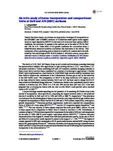
FIG. 1. GEM in a single crate configuration 共or兲 unified data acquisition system. Only one of the inputs of the EVE is connected to the EFVE output, thus working in the master+ slave configuration with internal clock enable. EoIS specifies event-of-interest selection logic.
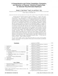
tion to increase throughput considerably. The DAS trigger signal may be generated by the GEM module if so configured upon event identification. This trigger generation may be delayed 共user programmable from 40 ns to 256 s in steps of 10 ns兲 to enable acquisition from any slow data converters. The entire CAMAC backplane interface is also implemented in the FPGA,with appropriate level converters. This may be easily adapted in the future to other standards without any changes in the front-end. The working of the GEM module in a unified data acquisition system is depicted in Fig. 1. Multiple GEM modules 共in separate CAMAC crates兲 may be connected in parallel as shown in Fig. 2. The module labeled “master” in the figure makes the final event identification decision. Thus GEM supports distributed data acquisition enabling a larger number of signals and throughput.
Trigger
CEout
EFVE
12
Clock Trigger
Slave GEMs
075114-2
3
Clock
CEin
Clock Trigger
Clock Trigger
EoIS
TGin
3
Accept
EVE CEout
4
3
PromptOut (Trigger)
3
CEin 3
Master GEM
CEout
EFVE
12
Clock
CE
3
CEin
EFVE
12
Clock Dist
CEout
EFVE
12
Clock SRC
3
3
CEin CE
6
LOCAL PEM
3
EFVE
12 6
LOCAL PEM
6 6
3
LOCAL PEM
3
GLOBAL PEM
4
EVE
12 6
GLOBAL PEM
8
GLOBAL PEM
4
4
FIG. 2. Depiction of using GEM in a distributed or a multi-crate configuration. EFVE provides a partial event identification information based on the connected event fragment. EVE provides a combined event identification from multiple crates. EoIS provides one of the four possible outputs possible.
075114-3
Rev. Sci. Instrum. 81, 075114 共2010兲
K. Rani and E. T. Subramaniam
Event Fragment Processing EFVE
e
Detectors and NIM Discriminator
l ab m m r a r e og ch Pr tret S
12
EFVE
EFVE
Event Recording GT0 Time Reference Unit
100MHz Clock CEin
CEout CC Reset Master/Slave
p
m
ta
eS
im
T
Clock FAN OUT
t en Ev of st r ee Int ction le Se
Global Event Processing
"1"
GC0 GC1 GC2 GC3
EVE
Clock Counter
100MHz Crystal module
EoI
Veto Selection System BUSY
TimeTAGReadOut nt ve l E tor a ob da Gl Vali
LookAtMe Event Counter EventTAGReadOut Strobe EC Reset
Trigger Global FANout
Strobe Generation Gate
EoI
GT0 GT1 GT2 GT3
LAM and Strobe Generation
FIG. 3. GEM information flow diagram.
III. FUNCTIONAL DESCRIPTION
The information flow diagram of the GEM and its configuration in master/slave mode is depicted in Fig. 3. The special feature of the GEM module is its master/slave architecture. An individual GEM itself is a combination of master and slave and can be used as required, either as slave or as master+ slave. The design adopted facilitates ease of maintenance, as well as hardware position independence. Despite the hierarchical sounding names of master and slave, the master does not have any special status compared to the slave; they are really equal in all aspects. Master is equipped with an on-board oscillator while slave reconstructs their clock on the basis of received clock. The master and slave are discriminated just by the way the ethernet Unshielded Twisted Pair 共UTP兲 cables and the daisy chained clock enable signals are connected. Apart from this, only the master is enabled 共through CAMAC commands兲 so as to start the “clock enable” daisy chain. The entire processing of event fragment encoding, event identification, timestamping, hit pattern recording, and the CAMAC backplane interface are all implemented in the FPGA. A. Event selection logic
This comprises of 12 discriminators which accepts NIM inputs 关IN共0兲-IN共11兲兴, which is actually a trigger request from individual detectors or a group of detectors. A level shifter/comparator converts the NIM inputs to LVDS using level translator chips. The input pulses are re-stretched to a user selected 共up to 128 s兲 width, depending upon the requirement of the experiment. Depending upon the event of
interest and its pre-defined conditions, the Event Fragment Validator Engine 共EFVE兲 is configured. Out of the many different possible methods available, the Programmable Event Mapper 共PEM兲 implemented using Configurable Logic Block 共CLB兲 共see Fig. 2兲 is chosen for its ease of implementation, speed, and flexibility to upgrade or modify. A small program written in C language produces the required bit values for the PEM to be filled in. The configuration consists of three PEMs based on CLBs each having 6 bit selection input and 3 bits of output in two stages. In first stage the 12 inputs are divided into two sets of 6 signals each and fed as selection inputs for the two PEMs of the first stage. The concatenated outputs of these two PEMs giving 6 bits is fed as selection input for the third PEM in the second stage giving 3 bits of output which forms the output of EFVE. The EFVE outputs from all the modules are transferred as LVDS through equal length CAT5 UTP cables to the module, which is configured as master to avoid timing discrepancy in the trigger requests coming from different slaves 共slave GEM including master itself兲. The same CAT-5 cable is used for clock distribution to the slaves, thus avoiding clock delay. Pre-emphasis and de-emphasis of LVDS signal has been implemented as a precaution to discard the random noise using LVDS buffers at both receiving and transmitting ends. Master receives a total 12 bits from 4 EFVEs. Now from these 12 EFVE signals, the Event Validation Engine 共EVE兲 decides the event of interest. This is again implemented using PEMs in two stages. The concatenated outputs of the first stage gives 8 bits, which is connected to the second stage PEM, which provides a 4 bit output. The
075114-4
Rev. Sci. Instrum. 81, 075114 共2010兲
K. Rani and E. T. Subramaniam
actual validation signal output is user settable as one of the four possible outputs of the EVE using CAMAC commands. This is implemented as 4:1 multiplexer and the output pulse is re-stretched to required value 共up to 128 s兲 by CAMAC commands. The LVDS output from the FPGA is converted to NIM levels using the emitter coupled logic of ultrahigh frequency NPN transistor array. GEM module provides different logic levels 关5 V transistor-transistor logic 共TTL兲, NIM, low voltage TTL 共LVTTL兲, ECL, LVDS兴 which are normally used in the acquisition systems but the conversion has not been shown in the figures for simplicity. Further validation or to avoid false triggering, a veto feature is provided in the system. For example two detectors firing just exactly within the user set time window T may give a false strobe for a double coincidence event selection, while recording will happen for single coincidence with one detector only. This happens due to the system delay and the delay in the cables. This can be avoided using this veto provision. By selecting the primarily fired detector, that is, the single coincidence output may be used as a veto after delaying it by a user set veto delay. This input, when present, will prevent any new event selection from occurring, thereby avoiding false triggering. One of the EVE outputs may be used as veto. The veto width and delay are user settable through CAMAC commands. This is implemented using 5:1 multiplexer which selects on the four EVE outputs and the fifth provided as a “no veto” state. The validation output is fed to the master, which gives out four outputs, one for each slave module. Upon receiving the accept signal, each and every slave module timestamps it with a resolution of 10 ns. This timestamp is used for synchronization while assembling the event fragment packets to form an event packet. At the same time the 12 inputs are also latched as “hit pattern” by each and every slave, which is used by the respective crate controllers to read only the effective signals. This can be accomplished by hit patternbased operating crate controllers such as LPCC, thereby reducing the dead time considerably. B. Global clock synchronization
A single-ended LVTTL crystal oscillator module running at 100 MHz forms the source for the time reference. The single-ended clock is passed through a clock manager and buffered to provide a fan-out of four LVDS clocks to be distributed via CAT-5 cables to up to four GEMs. This is the reference clock or global clock for all GEMs. “Global clock enable” is daisy chained to all GEMs. This signal is enabled via CAMAC command only in the master. This global clock 关共GC 共0–3兲兴 共see Fig. 3兲 and the enable signals 共CEin, CEout兲 provide a time reference to make a synchronized system. One of the slave is the master module itself. Equal length CAT-5 cables ensure minimal clock delay between different crates. To minimize the clock skew within the board, slave module reconstructs its own clock based on the master clock received and is used for all processes and time reference. The internal routing of the FPGA is done with complex appropriate routing and placement constraints so as to match the delays between different synchronous and asynchronous outputs.
TABLE I. CAMAC commands. A
F
Description
0 1 2 3 4 5 8 0 1 2 3 4 5 6 7 8 9 0 0 0 0 0 1 1 0
0 0 0 0 0 0 0 16 16 16 16 16 16 16 16 16 16 17 9 10 24 26 24 26 25
Read timestamp L-16 bits Read timestamp M-16 bits Read timestamp H-16 bits Read hit pattern Read event TAG Read total event Read DCM status Set block size 共0–65535兲 Timing window 共100 ns− 128 s兲 EOI width 共100 ns− 128 s兲 DAS strobe width 共1 – 256 s兲 Veto width 共1 – 128 s兲 Veto delay 共1 – 128 s兲 TTL gate width 共1 – 128 s兲 EOI selection 共0–3兲 1 of 4 Veto selection 共0–4兲 1 of 5 Test output Module enable 共bit-0:1-enable,0-disable兲 Reset time ref. counter Clear LAM Disable LAM Enable LAM Disable master Enable master Clear busy
As the time reference is the key of synchronization, every accepted event of interest needs to be associated with a time tag. Time tag is a 48 bit digital pattern, which is a 48 bit clock counter value at the occurrence of event of interest. As each individual module has an option to generate an internal enable signal through CAMAC command 共see Table I兲 or accept external enable signal 共CEin兲 by disabling the internal clock enable 关A共1兲 · F共24兲兴. Any module configured as master can generate an enable signal clock enable out 共CEout兲 and is transmitted to all slave modules, which are configured to accept the external CEin through daisy chaining to achieve clock synchronization. Clock counter in individual modules are reset to zero before start of the acquisition run, by CAMAC command “timestamp reset” to all GEMs individually in a multi-crate system, ensuring a timestamp within the accepted time limit. This acceptable time limit is decided by the time taken by the enable signal to reach the slave from master, i.e., the length of the cable. Once an event is validated by the master the validation is transmitted to all the slave modules so as to timestamp the event fragments with a resolution of 10 ns and a range of 32.5 days. This can be used during event re-building when packet assembling of the event fragment packets are done in the acquisition and analysis software package. C. Global trigger generation
The event logic is implemented to 共1兲 identify valid events and 共2兲 fan-out the valid event globally to maintain synchronization between fragments. This accepts a trigger in 共TGin兲, which is actually a user defined coincidence and provides four fan out for global trigger 共prompt out兲 after exam-
Rev. Sci. Instrum. 81, 075114 共2010兲
K. Rani and E. T. Subramaniam
INj (Crate−1)
Slave−1
u1
INi (Crate−1) p1
EFVE1
1
2
1
0
Slave−2
075114-5
INi (Crate−2) 1
EFVE2
0
1
0
INi (Crate−4) INj (Crate−4) 1
EFVE4
2
1
6
5
0
12345 6
EOI Sel. (2) TGin
p1
d1
p2
d2
Strobes
u2 − Output Width
u4 − DAS control Delay System Inherent
4321 5
u3 − Strobe Width
0
1234
EVE (input)
u1 − Time Window
Master
EFVE3
Slave−3
u2
Slave−4
User Programmed
INi (Crate−3)
p1 − EFVE processing p2 − EVE processing d1 − UTP cable delay
u3 u4
d2 − TGin cable delay.
DAS control
FIG. 4. GEM timing diagram.
ining the validity of event by checking that the system is enabled and not busy globally, in processing the previous event and all the modules are ready to accept the next available trigger. Busy signal of all the GEM modules in a multicrate DAS is connected in wired “OR” mode by using open collector outputs. Validity of event in terms of time resolution may be further cross-checked by introducing a veto signal, whose delay, width, and type are user settable by CAMAC commands to make sure that accepted event is with in the user specified time window. The event logic inhibits further inputs, preventing subsequent detector triggers from interfering with the downstream processing of an event providing a busy. This event is regarded as “accepted,” if it satisfies all the conditions defined by user and system. GEM which is configured as master keeps account of accepted events using a 16 bit event counter and generates a lookat-me 共LAM兲 when the user-defined block size is collected. Master is configured to keep the LAM enabled, while slaves are configured to keep the LAM disabled through CAMAC commands. “TGin” comes as a global event; if accepted, the system provides a busy signal indicating that the system is busy in event processing until reset by “CAMclear” signal from CAMAC crate controller which is actually an indication that the controller has read all the information latched in the modules related to the global event and now the system is ready to accept the next available valid trigger. GEM provides a facility to distribute effective trigger at local level providing the fan out for accepted events as “prompt out.” D. Local strobe generation
Strobe for all the modules within the crate is generated locally by the slave to simplify complexity of connection from master to slave. Upon receiving the “accept” signal, GEM provides three different signals. The first is the prompt
out, which can be used for time recording, say, “start” for “Time to Digital Converters.” A separate TTL strobe is generated whose width is programmable and may be used for “Analog to Digital Converters.” This is user settable through CAMAC command up to 128 s. A third signal is also provided whose delay is user settable and may be used for strobing the CAMAC crate controller to read the acquired data. Local strobe generation helps in reducing criss-cross of cables in multi-crate system.
E. Timing
In the given timing diagram 共see Fig. 4兲 timing information of all the signals has been given with reference to event fragment input. The inputs on arrival are re-stretched by the user set time window “u1.” The system inherent time for EFVE and EVE processing combine is less than 32 ns. The UTP cable connecting slaves to master amounts to “d1” and the lemo cable connecting event-of-interest output to TGin is “d2”
F. CAMAC interface
All CAMAC backplane signals which are of TTL levels are interfaced to the FPGA through series resistors to make it compatible with FPGA’s LVTTL levels. The read and write lines are multiplexed and then connected to the FPGA. This acts as a buffer as well reduces the pin count on the FPGA. CAMAC commands are decoded in the FPGA by a state machine implemented in it. All settings of GEM can be done remotely via CAMAC commands. This provides a jumper less configuration of the GEM. The CAMAC command set has been listed in Table I.
075114-6
Rev. Sci. Instrum. 81, 075114 共2010兲
K. Rani and E. T. Subramaniam
Event Of Interest Comparison
TABLE II. GEM hardware equivalence. Module
Traditional Technique
107
GEM : Distributed Configuration
Counts
106
105
104
IUAC TG/TR Phillips 7106 Phillips 744 Phillips 711 ORTEC CD 4010 ORTEC LF 4000 ORTEC GG 8010 ORTEC LA8000 Timestamp and sync ORTEC
Description Trigger gen./reader Bit pattern module Summing module Discriminator latch Coincidence unit Fan in/fan out Delay module Level translator ¯ NIM crate
103
IV. RESULTS AND DISCUSSION
102
101
0
10
0
4
8
12
16
20
24
28
Folds (or) Multiplicty FIG. 5. GEM. The digital approach event identification in comparison with traditional methodology in nuclear spectroscopy experiments.
G. Special features
The added advantage of implementing event selection logic by configuring FPGA CLBs as asynchronous PEMs is ease of event detection logic 共coincidence logic兲 modification. As the requirement of event-of-interest detection changes with the kind of experiments, the FPGA program that is easily up loadable can be changed accordingly without changing the hardware with a user settable time validation window ranging from 50 ns to 128 s. GEM also facilitates multi-strobe data acquisition that would be useful in nuclear structure physics experiments where the coincidence between prompt radiation particles and recoil nuclei has to be analyzed. Each system whether it is collecting data at target plane or focal plane can have independent triggers while sharing a global time reference by a global enable signal so that events of interest can be co-related during event rebuilding in software. The important features of GEM are enumerated below. 共1兲 12 input hit pattern. User settable re-stretched inputs from 50 ns to 128 s in steps of 10 ns. 共2兲 Four modules can be concatenated in master-slave mode using standard ethernet UTP 共CAT5兲 cables. 共3兲 Four programmable width 共50 ns to 5 s in steps of 10 ns兲 multiplicity outputs from 48 signals. 共4兲 Any of the multiplicity output may be used as veto input through remote commands. 共5兲 Timestamp with 10 ns resolution and 32.5 day range. 共6兲 Facilitates multi-strobe data acquisition systems with time tag reference.
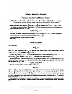
The GEM module has been used at the Inter University Accelerator Center 共IUAC兲 共Ref. 5兲 for experiments at the “Indian National Gamma Array” 共INGA兲 共Ref. 6兲. In these experiments, the GEM modules were configured for the detection of one/two/three/four simultaneous activation of detectors. There were two slaves and one master GEM module. The multiplicity spectrum 共number of co-incident detector activations兲 with a multiplicity factor of 2, using both the traditional hardware event selection and the GEM module is shown in Fig. 5. The traditional spectrum is shown as dotted line acquired from an experimental setup with 16O beam of 70 MeV on 94Mo. The solid line represents data acquired using GEM and the experimental setup was 19F beam of 105 MeV on 96Zr. The data collection is more efficient for the event of interest. The unwanted multiplicity, that is, the multiplicity less than that of interest is almost negligible. In addition, the large amount of hardware saved 共see Table II兲 simplifies the cabling, reduces setup times, costs, and human error possibilities. V. CONCLUSION
A fully programmable event validation for physics experiments has been designed, implemented, and tested. The design using a low cost FPGA of the Spartan-3 family facilitates reconfiguration on site for different experimental setups, thus providing higher flexibility. This when used in conjunction with intelligent crate controllers such as the LPCC increases greatly the throughput. As it is developed in house it provides ease of maintenance, as well as reduced cost and power. This is being extensively used in the INGA experiments held in IUAC. ACKNOWLEDGMENTS
The authors would like to thank the Indian National Gamma Array group, Inter University Accelerator Centre, New Delhi, and especially Mr. S. Muralithar for the help rendered in testing the module. The work owes it genesis to early discussions with Dr. A. K. Sinha. 1
2
IEEE Standard 共ANSI/IEEE Standards 583, 595, 596, 675, 683, 726, and 758兲. E. T. Subramaniam, K. Rani, B. P. Ajith Kumar, and R. K. Bhowmik, Rev. Sci. Instrum. 77, 096102 共2006兲.
075114-7 3
K. Rani and E. T. Subramaniam
See http://dx.doi.org/10.2172/7120327 for the PDF report of NIM standard 共http://ped.slac.stanford.edu:8080/eeip/NIM_Inst_System.pdf兲. See http://www.xilinx.com/support/documentation/spartan-3.html for the data sheet of the FPGA chip Spartan-3, which is the core of the developed module. 5 See http://www.iuac.ernet.in/ for information about the Inter University Accelerator Centre 共IUAC兲, the lab where the development took place. It is an experimental facility for universities and institutions of India in the fields of particle, nuclear, and material sciences. It is equipped with a 4
Rev. Sci. Instrum. 81, 075114 共2010兲 16 MV UD Pelletron, a Low Energy Ion Beam Facility, and many other offline facilities. A linear accelerator to extend the energy range of the pelletron is being built. 6 See http://www.iuac.ernet.in/research/nuclear_physics/INGA/INGA _main.html for information about the Indian National Gamma Array 共INGA兲, an experimental facility for nuclear spectroscopy experiments, where the module developed is being used in distributed data acquisition mode.