OFFLINE AND HARDWARE-IN-THE-LOOP VALIDATION OF THE GPS-BASED REALTIME NAVIGATION SYSTEM FOR THE PRISMA FORMATION FLYING MISSION Simone D’Amico(1), Sergio De Florio(1), Jean-Sebastien Ardaens(1), Toru Yamamoto(2) (1)
(2)
German Aerospace Center (DLR),Münchner Str. 20, 82234 Wessling, Germany,
[email protected] Japan Aerospace Exploration Agency, Institute of Aerospace Technology, Tsukuba, Ibaraki, 305-8505, Japan
ABSTRACT The German Aerospace Center (DLR) provides various key contributions to the Swedish led PRISMA formation flying mission. These comprise a redundant GPS hardware architecture for the two spacecraft, a real-time navigation software to support formation flying during all phases, and dedicated experiments for absolute and relative orbit control. This paper addresses the testing and validation of the GPS-based flight software as a standalone unit prior to its full integration into the spacecraft onboard computer. Thank to the model based PRISMA onboard software design, the navigation software can be executed on different platforms in a fully consistent manner. As illustrated in the paper, this allows a seamless transition between offline simulations using GPS flight data from the Gravity Recovery and Climate Experiment (GRACE) and real-time hardwarein-loop tests comprising real Phoenix GPS receivers and a 2x12 channels Spirent GSS7700 GPS signal simulator. Furthermore the complete application is ported to a Real Time Executive for Multiprocessor Systems (RTEMS) environment in a LEON-3 board, representative of the PRISMA onboard computer. Overall the test campaign shows the compliance of the navigation software to the challenging requirements of the PRISMA mission and paves the way for the PRISMA system level tests with hardware-in-the-loop. 1.
INTRODUCTION
The mission objectives of PRISMA may be divided into the validation of sensor and actuator technologies related to formation flying and the demonstration of experiments for formation flying and rendezvous. Key sensor and actuator components [1] comprise a GPS receiver system, two Vision Based Sensors (VBS), two Formation Flying Radio Frequency Sensors (FFRF), and a hydrazine mono-propellant thruster system. These will support and enable the demonstration of autonomous spacecraft formation flying, homing, and rendezvous scenarios, as well as close-range proximity operations. The mission is led by the Swedish Space Corporation (SSC) and foresees a launch of the two spacecraft in the first half of 2009. The spacecraft are named MAIN and TARGET and will be injected by a DNEPR1 launcher into a sun-synchronous orbit at 700-km alti-
tude and 98.2° inclination. A dusk-dawn orbit with a 6 or 18 h nominal local time at the ascending node (LTAN) is targeted. Maximum eclipse times of 23 minutes may occur for injections within ±1 h off the nominal LTAN, depending on the sun’s declination. Following a separation from the launcher, the two spacecraft will stay in a clamped configuration for initial system checkout and preliminary verification (cf. Fig. 1). Once the spacecraft are separated from each other, various experiments for formation flying and in-orbit servicing will be conducted within a minimum targeted mission lifetime of eight months. Spacecraft operations will be performed remotely from Solna, near Stockholm, making use of the European Space and Sounding Rocket Range (Esrange) ground station in northern Sweden. The S-band ground-space link to MAIN supports commanding with a bit rate of 4 kbps and telemetry with up to 1 Mbps. In contrast, communication with the TARGET spacecraft is only provided through MAIN acting as a relay and making use of a MAIN-TARGET intersatellite link (ISL) in the ultrahigh-frequency (UHF) band with a data rate of 19.2 kbps. The MAIN spacecraft has a wet mass of 150 kg and a size of 80 × 83 × 130 cm in launch configuration. In contrast to the highly maneuverable MAIN spacecraft, TARGET is a passive and much simpler spacecraft, with a mass of 40 kg at a size of 80 × 80 × 31 cm (cf. Fig. 1). Electrical power for the operation of the MAIN spacecraft bus and payload is provided by two deployable solar panels delivering a maximum of 300 W, whereas TARGET relies on one body-mounted solar panel providing a maximum of 90 W.
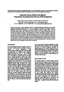
Figure 1 Artist’s impression of the PRISMA clamped configuration after launch (left), with the MAIN solar panels deployed (center), and the individual MAIN (right-top) and TARGET (right-bottom) spacecraft.
3rd International Symposium on Formation Flying, Missions and Technology, 23-25 April 2008, ESA/ESTEC, Noordwijk
The TARGET spacecraft applies a coarse three-axis attitude control based on magnetometers, sun sensors, and GPS receivers only. The MAIN spacecraft implements instead a three-axis, reaction-wheel based attitude control with independent three-axis delta-v capability. FOV
S67-1575-20 GPS Antenna
Phoenix GPS Receiver LNA 5V DC
Multiprocessor Systems (RTEMS) environment in a LEON3 board [8], representative of the PRISMA onboard computer, by means of Matlab/Simulink RealTime-Workshop. Overall the test campaign shows the compliance of the navigation software to the challenging requirements of the PRISMA mission [9] in terms of functionality, data interface, navigation accuracy, onboard memory and CPU load and paves the way for the full integrated PRISMA system level tests with hardware-in-the-loop.
R/F Switch
2. 2.1 5V DC S67-1575-20 GPS Antenna
LNA Phoenix GPS Receiver
FOV
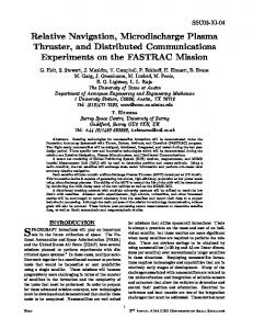
Figure 2 Redundant Phoenix GPS receiver system of MAIN and TARGET spacecraft. Two Phoenix GPS receivers are available (right), which are connected to two GPS antennas (left) with opposite field of view via a coaxial switch (middle). The German Aerospace Center (DLR) provides various key contributions to the PRISMA mission [2]. These comprise a redundant set of Phoenix GPS receiver and antenna systems for both spacecraft [3] (cf. Fig. 2), a GPS-based navigation software to support formation flying during all phases [4], dedicated experiments for relative [5] and absolute orbit control [6] as well as an on-ground automated Precise Orbit Determination (POD) for off-line verification purposes. This paper addresses the testing and validation of the GPS-based flight software at DLR as a standalone unit prior to its full integration into the spacecraft onboard computer. Thank to the model based PRISMA onboard software design, the navigation software can be implemented and executed on different platforms in a fully consistent manner. As illustrated in the paper, this allows a seamless transition between offline, real-time and hardwarein-the-loop tests during the validation phase. In particular offline simulations are first conducted in a Matlab/Simulink environment on a standard host PC. Here, the flight software is stimulated through different sources of GPS data with an increasing level of realism. Apart from the classical pure software simulations which make use of emulated GPS measurements, the paper presents numerical results obtained from the usage of real GPS flight data from the Gravity Recovery and Climate Experiment (GRACE) during the closest encounter of the twin satellites. As a next step a realtime hardware-in-loop test is conducted comprising two real Phoenix GPS receivers and a 2x12 channels Spirent GSS7700 GPS signal simulator [7]. Finally the complete application is ported to a Real Time Executive for
GPS-BASED NAVIGATION SOFTWARE Navigation Software Architecture
One of the main challenges of the PRISMA formation flying is the realization of an on-board navigation system for all mission phases which is robust and accurate even for various spacecraft orientations and frequent thruster firing for orbit control. The goal of the absolute and relative orbit determination is to achieve an accuracy of 2 m and 0.1 m, respectively (1D, r.m.s.) and to provide continuous position and velocity data of the participating spacecraft at a 1 Hz rate for guidance and control purposes as well as for the PRISMA payload [9]. The PRISMA onboard software (OBS) architecture consists of a layered structure with a Basic Software (BSW) level and an Application Software (ASW) level communicating with each other through dedicated message queues. While the BSW includes basic applications, device drivers and I/O-utilities, the ASW encapsulates all top-level applications like spacecraft navigation, control, telecommand and telemetry. As shown in Fig. 3 the GPS-based navigation system is split into three modules located in different OBS levels and running at different sample rates. The GPS interface (GIF) is part of the BSW, runs at 1 s sample time and is directly fed with GPS messages issued by the Phoenix GPS receivers on-board MAIN and TARGET. GIF handles GPS raw data formats and ephemerides, and performs data sampling as well as coarse editing prior to the GPS-based orbit determination. The GPS-based Orbit Determination (GOD) and GPS-based Orbit Prediction (GOP) are embedded in the ASW layer as part of the ORB core (30 s sample time) and the GNC core (1 s sample time), respectively. GOD implements an extended Kalman filter to process GRAPHIC observables as well as single difference carrier phase measurements from MAIN and TARGET. Attitude data from both spacecraft are applied to correct for the GPS receivers antenna offset with respect to the spacecraft center of mass. Furthermore, a history of maneuver data is provided to GOD and taken into account in the orbit determination task. GOD performs a numerical orbit propagation which is invoked after the
measurement update and provides orbit coefficients for interpolation to GOP for both spacecraft. BSW (1 s)
ORB (30 s)
GPS MAIN GPS GIF
GPS Data
MAIN Attitude
ACC
MAIN Man.
Orbit Data
GOD
GOP AFC
ISL GPS
User
AOK Man. Cmd.
SCA
GNC (1 s)
GNC, etc.) implementing guidance, navigation and control, thermal control, power control, payload control functionalities etc.. All these application-cores are executed through a real-time monotonic scheduler, i.e. they all have a specified sample time and their priority depends on the sample time: the smaller the sample time, the higher the priority.
CMD MAIN HTH
TARGET GPS
MM TARGET Attitude
SS
TARGET
Figure 3 Simplified architecture and data interface of the GPS-based software for PRISMA. The navigation modules (GIF, GOP and GOD) as well as the control modules (AOK, AFC) are incorporated in three onboard software cores (BSW, ORB, GNC) executing at 1 s and 30 s sample times on the MAIN spacecraft. The GOP module interpolates the orbit coefficients provided by GOD and finally supplies the various GNC core functions as well as the PRISMA payload with continuous position and velocity data of MAIN and TARGET. Due to the different data rates of the GPSbased navigation modules, orbit maneuver data have to be taken into account in both GOD and GOP (cf. Fig. 3). In particular at each GNC step, the GOP task accounts for maneuvers which have not been considered by GOD in the last orbit determination/prediction process. Among the users of the GPS-based navigation data the Autonomous Formation Control (AFC) and Autonomous Orbit Keeping (AOK) modules are located in the GNC and ORB cores respectively. 2.2
Overall Development and Validation Concept
The PRISMA Onboard Software (OBSW) development at the Swedish Space Corporation (SSC) makes use of the Model Based Design (MBD) approach and is completely based on Matlab/Simulink [10]. The MBD method raises the abstraction level for the system development and is especially suited to efficiently handle complex systems like e.g. the ones required to implement formation flying missions. The adoption of this development strategy can be compared to previous steps which have been taken in the history of software programming languages, like for example from assembler to C/C++, switching from a lower abstraction level language to a higher one. MBD can be seen as a natural step in this evolution chain, where emphasis is given to system engineering instead of focusing on software engineering. As stated earlier, the PRISMA OBSW consists of two main layers, BSW and ASW respectively. The ASW consists of a number of application-cores (e.g., ORB,
Figure 4 Illustration of software development (top) and software validation (middle) environments at DLR and consequent integrated system level tests (bottom) at SSC. The functionalities of the Orbit Propagator, GPS Emulator and Flight Software are located in different hardware units during the development and validation phase and are indicated between quotes. The application cores are implemented as input/output functions. When the desired inputs and outputs of the application-cores have been specified, parallel software
development is made easy. A dummy-core can always replace the real application core and the necessary services, as specified by the core-interface, and is prepared at the same time as the core-algorithms are being developed. The DLR software contribution to the PRISMA OBSW has to be pictured in this frame and consists of specific application-cores within the ASW. The real-time navigation system development follows the same overall approach but makes extensive use of C/C++ modules to implement the computationally intensive core navigation functions. Use of Simulink is thus restricted to wrappers providing the abstract top level software and interface description. This enables a fully consistent validation of the flight software as a standalone unit at DLR prior to the system integration. As illustrated in Fig. 4, a step-wise approach is adopted for the validation of the navigation system. In a first phase the flight software, wrapped through dedicated Simulink S-functions, is executed on a standard laptop PC (cf. Fig. 4, top) and stimulated by different sources of raw GPS data. The simplest simulations make use of emulated GPS measurements generated by the Phoenix EMulator (PEM) software. PEM allows a realistic modeling of measurements issued by a GPS receiver in LEO. More specifically, PEM emulates the output messages for raw measurements, navigation solutions and broadcast ephemerides generated by the Phoenix GPS receiver. As a next step raw single frequency GPS data (from JPL’s BlackJack receivers) collected during the swap phase of the GRACE satellites are used (December 9-10, 2005). During this period, both satellites are flying in close formation (baseline