We chose the Speeded-Up Robust Features (SURF) descriptor proposed by [1] and .... et al. estimate that these blocks are 8 Ã 8 on a GeForce 7800. GTX [7], or 64 .... Both the width and height are reduced by a factor of two at each level, so ...
GPU Accelerating Speeded-Up Robust Features Timothy B. Terriberry, Lindley M. French, and John Helmsen Argon ST, Inc., 12701 Fair Lakes Circle, Fairfax, VA 22033 E-mail: {Tim.Terriberry, Lindley.French, John.Helmsen}@argonst.com
Abstract— Many computer vision tasks require interest point detection and description, such as real-time visual navigation. We present a GPU implementation of the recently proposed SpeededUp Robust Feature extractor [1], currently the state of the art for this task. Robust feature descriptors can give vast improvements in the quality and speed of subsequent steps, but require intensive computation up front that is well-suited to inexpensive graphics hardware. We describe the algorithm’s translation to the GPU in detail, with several novel optimizations, including a new method of computing multi-dimensional parallel prefix sums. It operates at over 30 Hz at HD resolutions with thousands of features and in excess of 70 Hz at SD resolutions.
I. I NTRODUCTION Feature point detection and description is a necessary tool for many computer vision tasks, such as visual navigation, automatic target recognition and tracking, structure from motion, registration, calibration, and more. By picking out only the most salient points of an image that can be repeatably localized across different images, it vastly reduces subsequent data processing. However, feature extraction still remains a major bottleneck for many implementations. For example, accurate GPS-denied visual navigation on moving vehicles requires 30 Hz frame rates on large images [2]. Improving the speed of feature extraction reduces the size, weight, and power requirements of these systems, reducing deployment costs, so we have sought to implement the most appropriate extraction algorithm on readily available commercial hardware. Since features can be viewed from different angles, distances, and illumination, it is important that a feature descriptor be relatively invariant to changes in orientation, scale, brightness, and contrast, while remaining descriptive enough to be correctly matched against a pool of thousands of candidates. We chose the Speeded-Up Robust Features (SURF) descriptor proposed by [1] and described in Section II. This produces descriptors half the size of previous algorithms, such as the Scale-Invariant Feature Transform (SIFT)1 [3], while retaining the same matching performance. Smaller feature vectors increase the speed of subsequent matching operations, while themselves being less expensive to compute. However, SURF cannot yet achieve interactive frame rates on a traditional CPU. Inexpensive Graphics Processing Units (GPUs) can significantly accelerate image processing tasks such as feature extraction. There are already multiple GPU implementations of SIFT available [4], [5]. We have implemented SURF on the GPU, as described in detail in Section III. Our benchmarking 1 The University of British Columbia holds a patent on locating image features and performing object detection using SIFT.
results, detailed in Section IV, show SURF is more than three to five times faster than SIFT on a GPU and orders of magnitude faster than on the CPU. II. T HE SURF A LGORITHM This section reviews the original SURF algorithm. We defer some of the details to the next section, which discusses our GPU implementation, but we highlight the main points here. SURF locates features using an approximation to the determinant of the Hessian, chosen for its stability and repeatability, as well as its speed. An ideal filter would construct the Hessian by convolving the second-order derivatives of a Gaussian of a given scale σ with the input image. This is approximated by replacing the second order Gaussian filters with a box filter, as illustrated in Fig. 3. Box filters are chosen because they can be evaluated extremely efficiently using the so-called integral image, II, defined in terms of an input image I as II(x, y) =
y x X X
I(i, j) .
(1)
i=0 j=0
Given II, the sum over any arbitrarily-sized, axis-aligned 2D region can be computed in just four lookups. To achieve scale invariance, the filters are evaluated at a number of different scales, s, and the 3 × 3 × 3 local maxima in scale and position space form the set of detected features. Here s = σ, the scale of the Gaussians used to derive the box filters. A minimum threshold H0 on the response values limits the total number of features. The location x0 of each feature is then refined to sub-pixel accuracy via [6] � 2 �−1 ∂ H ∂H x ˆ = x0 − , (2) ∂x2 ∂x where x = (x, y, s)T are scale-space coordinates and H = |det(H)| is the magnitude of the Hessian determinant. The derivatives of H are computed around x0 via finite differences. Rotation invariance is achieved by detecting the dominant orientation of the image around each feature using the highpass coefficients of a Haar filter in both the x and y directions inside a circle of radius 6s. The size of the Haar filter kernel is scaled to be 4s×4s, and the sampling locations are also scaled by s, which is easily accomplished using the integral image. The resulting 2D vectors are weighted by a Gaussian with σ = 2.5s and then sorted by orientation. The vectors are summed in a sliding window of size π3 , and the orientation is taken from the output of the window with the largest magnitude. Once position, scale, and orientation are determined, a feature descriptor is computed, which is used to match features
across images. It is built from a set of Haar responses computed in a 4 × 4 grid of sub-regions of a square of size 20s around each feature point, oriented along the dominant orientation. Twenty-five 2D Haar responses (dx , dy ) are computed using filters of size 2s × 2s on a 5 × 5 grid inside each sub-region and weighted by a Gaussian with σ = 3.3s centered at the interest point. Bay et al. [1] specify that the responses dx and dy are to be oriented relative to the feature’s dominant orientation, but not how to compute them. Since the integral image can only sum axis-aligned regions, we compute axis-aligned responses and rotate the resulting 2D vector.PEachP sub-region a four-dimensional vector P constructs P v = ( dx , dy , |dx |, |dy |) from these responses. Combining the vectors v from each sub-region yields a single 64dimensional descriptor, which is normalized to a unit vector to provide contrast invariance. As a final discriminator, the sign of the trace of the Hessian matrix is used to distinguish light-on-dark features from dark-on-light, so that one can skip comparing the former against the latter. The total algorithm runs in approximately 354 ms on a 3 GHz Pentium IV for an 800 × 640 image [1], or at just under 3 Hz. The exact time varies with the number of features detected. III. I MPLEMENTATION This section outlines how the major pieces of the SURF algorithm are implemented on the GPU. Our implementation was written in Cg using OpenGL, since it was targeted towards a mobile platform with a GeForce Go 7 Series card, and mobile versions of the 8 Series and higher cards were not yet available. The bottleneck for many of our calculations is memory bandwidth. The top of the line GeForce Go 7950 GTX has a memory bandwidth of 44.8 GB/s, more than two to four times that of a high-end CPU system, but this bandwidth is shared among 24 fragment shaders. Furthermore, this memory can only be accessed via texture units, which load an entire 2D block of memory into the texture cache on every cache miss in order to use the memory bus efficiently. Govindaraju et al. estimate that these blocks are 8 × 8 on a GeForce 7800 GTX [7], or 64 times larger than the request. Careful use of the texture cache is vital to obtaining good running times. A. Integral Image Computation The primary workhorse of the SURF algorithm is the integral image, which is used to compute box filter and Haar filter responses at arbitrary scales in constant time per pixel. Since it must be computed over the entire image, it is one of the more expensive steps, and has been heavily optimized. We will use some of the same ideas when computing feature orientations, so we go over them in some detail. Even representing these sums on 7 Series cards is a problem, since unlike the 8 Series, they do not support 32-bit integer textures. The 23 bits of precision available in a floating point texture have sufficient accuracy only for images less than 215 pixels in size (about 181 × 181). In addition, OpenGL’s representation of 8-bit input values as a floating-point number between 0 and 1 produces highly-correlated rounding errors,
which can accumulate into as much as a 1% to 2% error over the whole image. Instead, we split the result into a four-component vector of single-precision floats. The first component contains an integer multiple of 212 , the second an integer between 0 and 212 − 1, and the third a floatingpoint number between 0 and 1. We store the original pixel values from the input image in the fourth component, since the GPU promotes three-component textures to four, anyway. This helps to avoid some extra lookups later. This format can represent the sum of any number of pixels up to the maximum texture size supported by a 7 Series GPU, 4096 × 4096. The individual components can be subtracted from their neighbors without causing destructive cancellation, and the differences accumulated to produce a total result without undue precision loss. However, keeping the different components in the proper range during construction of the integral image requires several expensive modf operations, so the number of these extended-precision additions (EPAs) should be minimized. We also round the third component to 1 the nearest multiple of 255 after each step, which avoids the accumulation rounding errors. Counterintuitively, this measured as slightly but consistently faster than omitting the rounding step, possibly due to better instruction scheduling. 1) 1D Parallelization: The computation of the integral image itself is a classic parallel prefix sum problem. It can be implemented as a prefix sum on each row, followed by a prefix sum on each column of the output [8]. The naive serial solution minimizes the total number of EPAs and can be computed in parallel over all the rows (resp. all the columns) at once by rendering thin vertical (resp. horizontal) quadrilaterals. This requires a ping-pong process going back and forth between two textures to avoid read-after-write dependency problems [9]. Unfortunately, doing so appears to flush the input image from the texture cache, despite the fact that it is not one of the textures being rendered to. We verified this experimentally by reducing the number of rows (resp. columns) computed in parallel as described in [7] to a level that should have allowed for optimal cache reuse of the input image. Instead, the execution time increased linearly with the number of primitives rendered. This cache flush gives the naive algorithm particularly poor cache behavior, since each cache miss causes an entire 2D block to be read into the texture cache from main memory, even though only a single 1D row or column of the block will be used. The output also winds up in alternate columns (resp. rows) and must be copied to a common texture. This can be done by outputting all the columns (resp. rows) as they are computed to a separate, third texture using multiple render targets (MRT) to avoid additional uncached texture reads. The total computation requires approximately 4N reads, 2N EPAs, and 4N writes to compute the whole integral image, ignoring lower-order (constant) terms, where N is the number of pixels. However, because of the poor cache locality, the read memory bandwidth required is actually 8 times larger. 2) 2D Parallelization: An approach that exhibits much better 2D cache locality can be derived by implementing the
U (2)
sum within a row (resp. column) in parallel as well, using Blelloch’s work-efficient algorithm [10]. This algorithm has a straightforward GPU adaptation, as presented in [11], which we detail here. The algorithm operates in two phases, an upsweep and a down-sweep, to construct two image pyramids, (k) (k) (k) (k) Ux and Dx , (resp. Uy and Dy ), where k is the pyramid level. Each level is half the width (resp. height) of the previous level and is defined by the following set of recurrences: Ux(k) (x, y) = Ux(k−1) (2x, y) + Ux(k−1) (2x + 1, y) , (k+1) x even, (b x2 c, y) , Dx (k+1) x (k) Dx (x, y) = Dx (b 2 c, y) (k) + Ux (x − 1, y), x odd,
(3)
Uy(k) (x, y)
(5)
=
Dy(k) (x, y) =
Uy(k−1) (x, 2y) + Uy(k−1) (x, 2y (k+1) (x, b y2 c) , y even, Dy (k+1) Dy (x, b y2 c) (k) + Uy (x, y − 1), y odd. (K )
+ 1) ,
(4)
a...d
U (1)
a...b
U (0)
a
c...d b
c
D(3)
0
D(2)
e
f
a...d
0
a...d a...b
0 a
D
(0)
0
e...f
a...b
a...d c
a
a...f e
a...b a...c a...d a...e a...f
(6)
(K )
d
(a) Up-sweep
D(1)
Both down-sweeps are initialized with Dx x = Dy y = 0, where Kx (resp. Ky ) is the number of levels required to reduce the width (resp. height) to 1. As can be seen in Fig. 1, the final output of D(0) does not include the original pixel value at each location. Blelloch calls this output a prescan. We can include the original input value by outputting one extra term and re(0) 0(0) indexing the final output to be Dx (x, y) = Dx (x + 1, y) 0(0) (0) (resp. Dy = Dy (x, y+1)). This re-indexing is incorporated into the final pass of the rendering, so that the extra 0 at the beginning of the last level is never output. The x up-sweep is (0) initialized with Ux = I, the input image, and the y up-sweep 0(0) (0) is initialized with Uy = Dx , the output of the row sums. The whole algorithm requires approximately 10N reads, 4N EPAs, and 6N writes to compute the sums in both directions. The even-odd conditional prevents half the fragment shaders from doing useful work during the down-sweep, giving an effective cost of 6N EPAs. However, benchmarks showed that this approach was slightly faster than rendering the even and odd pixels into separate quadrilaterals and then using more complicated texture addressing to look up the correct value in the next pass. The total cost of this algorithm is much greater than the naive 1D parallelization, but cache locality is very good. During the up-sweep, all of the texels in every 2D block referenced are used by neighboring fragments. During the down sweep, only half of each U (k) block is used, but each pixel of D(k+1) is used twice. However, it is possible to reduce the memory bandwidth even further by computing the sums for both directions simultaneously. We now derive a novel algorithm for doing so. 3) Novel 2D Parallelization: The basic process is an extension of Blelloch’s two-phase algorithm to operate on multiple dimensions simultaneously. However, the down sweep requires additional auxiliary sums, since the difference between two adjacent pixels now contains the sum of an entire row or column, not just a single pixel value. These auxiliary sums can still be computed in less time than it takes to do two
e...f
(b) Down-sweep Fig. 1. The two phases of Blelloch’s parallel prefix sum algorithm for a single row or column [10]. The sum output at each pixel location does not include the original input value at that location, so one more value must be output than input. The size of each level of the down sweep is half that of the previous level, rounded up. The size of the corresponding level of the up-sweep is always one less than that of the down-sweep.
applications of Blelloch’s original algorithm. The new up-sweep simultaneously constructs three pyramids, U (k) , H (k) , and V (k) , using MRT, defined by U (k) (x, y) = U (k−1) (2x, 2y) + U (k−1) (2x + 1, 2y)
(7)
+ U (k−1) (2x, 2y + 1) + U (k−1) (2x + 1, 2y + 1) , H (k) (x, y) = U (k−1) (2x, 2y) + U (k−1) (2x + 1, 2y) , V
(k)
(x, y) = U
(k−1)
(2x, 2y) + U
(k−1)
(2x, 2y + 1) .
(8) (9)
Both the width and height are reduced by a factor of two at each level, so this requires 4N/3 reads, N EPAs2 , and N writes for the entire up-sweep. The two half-sums H (k) and V (k) are used to compute the row and column sums at the even locations: X
(k)
(x, y) =
Y (k) (x, y) =
x−1 X i=0 y−1 X
H (k) (i, y) ,
(10)
V (k) (x, j) .
(11)
j=0
X (k) (x, y) and Y (k) (x, y) do not include the original value of H (k) (x, y) or V (k) (x, y) in their sum and thus correspond to one of Blelloch’s prescans. Hence we can simply use the approach outlined in Section III-A.2 to compute them, without 2 We only use one EPA per output, regardless of how many terms appear in the sum. Intermediate results are computed using ordinary vector addition with no observed accuracy loss.
H (4)
U (4)
U (3)
V (4)
H (3) V (3)
U (2)
H (2)
V (2) U (1) H (1)
V (1) U
(0)
Fig. 2. The up-sweeps for our proposed 2D parallel prefix sum algorithm. The down-sweeps are constructed similarly, with the arrows reversed. TABLE I I NTEGRAL I MAGE A LGORITHM E FFICIENCY. Algorithm
Reads
1D Ping-Pong 4N 2D Blelloch 10N 2D Proposed 7.67N
Cache Efficiency
EPAs (effective) Writes
12.5% 2N 100.0% 4N 109.5% 3.33N
(2N ) 4N (6N ) 6N (4.33N ) 4.33N
Real Speed-up 1.00 3.89 4.63
the indexing adjustments required to produce a full scan. We will never need X (0) or Y (0) , so this computation starts off already one quarter the size of the original image. The total work required to compute X (k) and Y (k) at all the remaining levels is 10N/3 reads, 4N/3 EPAs, and 2N writes. Given these inputs, we can define the main down-sweep: (k+1) x x even, y even, (b 2 c, b y2 c), D y (k+1) x D (b c, b c) 2 2 y (k+1) x + Y (b c, 2 b 2 c), x odd, y even, y x (k+1) (b 2 c, b 2 c) D (k) (k+1) D (x, y) = + X (b x2 c, b y2 c), x even, y odd, (12) D(k+1) (b x2 c, b y2 c) + X (k+1) (b x c, b y c) 2 2 y (k+1) x + Y (b c, b 2 2 c) + U (k) (x − 1, y − 1), x odd, y odd. The entire down sweep requires 3N reads, N EPAs, and 4N/3 writes, giving grand totals of of 23N/3 reads, 10N/3 EPAs, and 13N/3 writes. This represents reductions from the method of Section III-A.2 of 23%, 17%, and 28%, respectively, while preserving its good cache locality properties. Extending this new algorithm to higher dimensions is straightforward. Table I gives a summary of the computational costs of each of the algorithms for computing the integral image. The effective number of EPAs (in parentheses) takes into account the fact that some fragment shaders will be idle while an EPA is being performed for neighboring pixels due to GPU limitations on branching. The cache efficiency is computed as
the total number of reads divided by the total number of pixels loaded into texture cache, assuming the cache consists of 8×8 blocks and re-use by nearby pixels is ideal. The speed-up over the 1D ping-pong method was measured at 1280 × 1024. Pixel re-use will obviously not be ideal at the top of the pyramid, where there may be fewer nearby pixels than the size of a texture block. As pointed out by [11], it is also inefficient to use numerous passes on a small number of pixels, since there may be fewer fragments to render than fragment shaders, and setting up each pass involves additional overhead. Hence when the total size of U (k) falls below a threshold T0 , we switch to a simpler but asymptotically less efficient algorithm based on [12] to compute D(k) . This is a ping-pong method, computing an output T (j+1) from an input T (j) via the relation (j) T (x − d, y − d) + T (j) (x, y − d) + T (j) (x − d, y) (j) x ≥ d, y ≥ d, + T (x, y), (j+1) (j) (13) T (x, y) = T (x − d, y) (j) + T (x, y), x ≥ d, y < d, (j) T (x, y − d) + T (j) (x, y), x < d, y ≥ d, (j) T (x, y), x < d, y < d , where d = 2j . T (0) is initialized to U (k) and J total iterations are performed, where J is chosen so that 2J is at least as large as the larger dimension of U (k) . The output D(k) is constructed from T (J) by prepending a row and column of zeros. A threshold around T0 = 8192 pixels gives the optimal running time. Unlike [11], we find no benefit to using a similar optimization with Blelloch’s original algorithm, because we are applying it to so many rows (resp. columns) in parallel. B. Feature Detection Having constructed the integral image, we turn to the evaluation of the box filters used to locate interest points. The original SURF paper [1] does not give a precise specification of the shape of the box filters to use after the first scale, and some of the details of how the scales are sampled are ambiguous. We have elected to use a slightly modified scheme which is more regular and simplifies the subsequent location of local maxima and pixel interpolation. Like Bay et al. [1], we use filters of size 9, 15, and 21 at the first three scales. The precise layout of the box filters is governed by four parameters Q1 , . . . , Q4 , as illustrated in Fig. 3. Table II gives the values we use for these parameters. These are the same as used by Bay et al. at the first scale. They did not specify exact values at the remaining scales, so we have chosen our values in a manner that simplifies some of the optimizations introduced below. Bay et al. derive their size 9 filters as the best box-filter approximation of the second-order derivatives of a Gaussian with scale σ = 1.2 and compute the scale associated with the rest of the filters based on the ratio of their size to that of the base filter. However,
1
Q1
−2
1
Q1
1
−1
−1
1
Q4
Q2
Q3
Q1
(a) Gxx
Q4
1
Q1
−2
Q1
1
Q1
Q3
Q3
Q3
Q2
(b) Gxy
(c) Gyy
Fig. 3. Box filters approximating 2nd-order partial derivatives of a Gaussian. TABLE II B OX FILTER PARAMETERS FOR THE FIRST THREE SCALES . Filter Size
Q1
Q2
Q3
Q4
σ
9 15 21
3 5 7
5 9 11
3 5 7
1 1 1
1.593 2.700 3.680
the real question one should ask is, what is the scale of a feature that will respond to a given box filter? We compute the best σ for a set of box filters by optimizing the sum of the correlation coefficients between the box filters and their ideal Gaussian counterparts, yielding the values in Table II. These differ significantly from the values given by Bay et al., but put scale estimates between images on a sounder basis. After reaching a filter size of 27, Bay et al. begin incrementing by 12, for several steps, then 24, etc., simultaneously doubling the sampling interval at which filter responses are computed each time the filter step size doubles. Instead, we generate all successive levels by scaling the parameters for the first three filters by a power of three. The estimated σ values and the sampling interval are scaled as well, so that each successive triplet of scales considers 19 as many pixels. This samples features more uniformly in log-scale space and makes it much easier to manage the transitions between sampling interval sizes. Factors of three are used instead of factors of two in order to keep all of the filter parameters odd, ensuring that we can always sample them at integer locations. This change means that we use fewer samples than Bay et al. at higher scales. Whereas they use box filter sizes of {9, 15, 21, 27, 39, 51, 63, . . .}3 , we use {9, 15, 21, 27, 45, 63, . . .}, i.e., one less scale to cover the same range. While we have not investigated the exact effect on accuracy of sampling fewer scales at fewer points, we expect it to be small, while enabling a large reduction in computation. 1) Box Filter Optimization: Calculating box filter responses to approximate the Hessian determinant is quite expensive, especially at the first three scales, since they are sampled at every pixel in the image. All of the remaining scales combined require a fraction of the time those do. A straightforward implementation involves 32 distinct lookups per pixel, or over 126 million lookups for the lowest three scales of a 1280 × 1024 image. This takes over 120 ms by itself. 3 Presumably. The exact transition point to increments of 24 is unclear from the original paper, but probably occurs after size 63.
In order to overcome this bottleneck we use a multi-pass approach that takes advantage of the fact that many of the intermediate values are differences between two values in the integral image separated by a small set of common distances. Some of these differences will also be used by nearby pixels. Thus by computing them once and sharing them, the total required memory bandwidth is reduced. Let us define some expressions for these differences around a point (x, y): � � � � n−1 n+1 n δx = II x + , y − II x − ,y (14) 2 2 � � � � m−1 m+1 δ n×m = δxn x, y + − δxn x, y − (15) 2 2 From these we can construct the following multi-pass algorithm for the first scale: 3 5 • Pass 1: Compute δx and δx (4 lookups). 3×3 3×5 • Pass 2: Compute δ ,δ , and δ 5×3 from the output of pass 1 (4 lookups). 9 9 • Pass 3: Compute the full box filter responses Gxx , Gxy , 9 and Gyy from the output of pass 2, and the resulting Hessian determinant, H9 (9 lookups). This reduces the total number of texture lookups for a single scale from 32 to 17, or a savings of 47%, which is almost exactly the reduction in observed running time. We can eliminate even more common sub-expressions by considering the first three scales simultaneously. These involve regions of size 3 × 3, 3 × 5, 5 × 3, 5 × 5, 5 × 9, 7 × 7, 7 × 11, 9×5, and 11×7. Unfortunately, there are nine such region sizes involving five different lengths. MRT only supports writing to multiple textures of the same format—limiting us to a multiple of 1, 2, or 4—and can only write to four textures at a time on 7 Series cards, meaning the closest we can come to 9 outputs is 8 or 12. Therefore we will have to be more clever in how we split up intermediate computations between passes. We define two additional difference terms: � � n×m ∆n×m = δ n×m x + n+1 x − n+1 (16) x 2 ,y − δ 2 ,y ∆n×m = δxn (x, y + m) + δxn (x, y − 1) y − δxn (x, y) − δxn (x, y − m − 1)
(17)
Armed with these, we construct the five-pass algorithm outlined in Table III. This requires only 40 lookups to compute the Hessian determinants of three scales simultaneously, or a 22% savings over computing them individually. Improved cache locality yields a 55% better run time, for a total savings of 77% over the straightforward algorithm. In addition, only three temporary textures, T0 , T1 , and T2 are needed, and all three outputs wind up in the same texture, greatly reducing the number of lookups needed for the next step. 2) Non-max Suppression and Sub-pixel Interpolation: Once the Hessian determinant values have been computed for a triplet of scales, local maxima over a given threshold become interest points. Using two passes, one for x and one for y, we construct a texture with the local maximum of all three scales in a 3 × 3 window, using the sign bit to store whether the value at that location was itself the local maximum. In
TABLE III M ULTI - PASS BOX FILTER OUTPUTS FOR THE FIRST THREE SCALES .
Inputs Lookups Outputs R G B A
per feature. This limits the total number of features detected in the frame to 4096, which should be more than sufficient.
Pass 1
Pass 2
Pass 3
Pass 4
Pass 5
C. Haar Responses
II 8 T0
T0 12
T2 7 T1
T0 , T1 8 T2
G15 xx G21 xx ∆7×7 x δ 11×7
Both orientation detection and feature descriptor construction require computing hundreds of Haar filters. Because feature locations are sub-pixel accurate and the scale values are not integers, the integral image must be sampled at non-integer locations. This interpolation must be done manually, and a naive implementation requires four integral image lookups:
δx3 δx5 δx7 δx11
T1
T2
T1 5 T0
∆3×3 y δ 3×5 G9yy ∆5×5 y
δ 5×9 δ 7×7 δ 7×11 δ 11×7
H9 G15 xy δ 9×5 —
H9 H15 H21 —
II(x + ∆x, y + ∆y) = (1 − ∆y)(1 − ∆x)II(x, y) addition, a local average of the 3 × 3 group of values from the highest scale is stored in the fourth channel, which will be used during sub-pixel interpolation. Several rounds of Early Z Culling [13] are then used to perform inter-scale suppression. Each round renders a quadrilateral at a progressively greater depth, and the pixels that pass the round are “discarded” by the fragment program, preventing their depth values from being written; no color values are written. Normally using discard disables Early Z, but we have found that enabling OpenGL’s EXT depth bounds test extension prevents this. Conceptually we appear to be writing a depth value for almost every pixel every round, but the GPU’s hierarchical Z-buffer absorbs most of this cost. Each pass after the first takes just a few microseconds. One could use the stencil buffer instead, but this has driver issues at the time of this writing. The first round passes a fragment if its local maximum across the three scales is larger than the threshold. The second round addresses the cases where the lower scale or the upper scale was the local maximum. In the first case, we compare against the maximum over a 9 × 9 area from the previous scale by looking up nine 3 × 3 maxima. In the second case, we look up nine Hessian determinants from the scale above and bilinearly interpolate the corresponding 3 × 3 region of the current scale. Because the 7 Series GPUs do not support bilinear interpolation of 32-bit float textures, this interpolation must be done manually. However, because the number of feature points is very small, this is extremely quick. A final pass computes the sub-pixel location of the remaining feature points using (2). If the feature is at the first scale in a triplet, we use the local 3 × 3 average from the scale below when computing finite differences. If the feature is at the third scale, we use bilinearly interpolated values from the scale above. We currently accumulate feature locations from all three scales into the same texture. If the first and third scale are both local maxima, only the latter becomes a feature. 3) Point List Generation: Once the sub-pixel interpolation is complete, the coordinates of the interest points are extracted from the image and assembled into a list using the vec4 variant of Ziegler et al.’s HistoPyramid algorithm [14]. This algorithm reads back a single pixel value to determine the total number of features; this is the only read-back we perform before retrieving the final feature vectors. Unlike Ziegler et al., we use a one-dimensional texture to store the list of features, since many of our subsequent steps will use an entire row of pixels
+ (1 − ∆y)∆xII(x + 1, y) + ∆y(1 − ∆x)II(x, y + 1)
(18)
+ ∆y∆xII(x + 1, y + 1) , where ∆x, ∆y ∈ [0, 1]. Since we have the original image value in the fourth component of the integral image, we can reduce this to three lookups by noting that II(x, y) = II(x + 1, y) + II(x, y + 1) + I(x + 1, y + 1) − II(x + 1, y + 1) .
(19)
However, with some pre-computation, this can be reduced even further. Let R(x, y) and C(x, y) be defined as the sum of a single row or column originating at pixel (x, y): R(x, y) =
x X i=0
I(i, y) ,
C(x, y) =
y X
I(x, j)
(20)
j=0
These sums are trivial to compute from II and can be packed into two components instead of three, since they cover at most 4096 pixels. We store them both in a single four-component texture and use the relations II(x + 1, y) = II(x + 1, y + 1) − R(x + 1, y + 1)
(21)
II(x, y + 1) = II(x + 1, y + 1) − C(x + 1, y + 1)
(22)
to compute a sub-pixel accurate value with just two lookups. It may be surprising that this approach provides any appreciable speed-up, since all the values of II required are right next to each other, and one might reasonably expect them to be available in the texture cache, while computing the RC texture requires three extra lookups per pixel. However, when computing Haar responses, the sampling locations are no longer aligned to a regular grid and are spaced far apart at higher scales. The 7 Series fragment shaders use a SIMD architecture on 2×2 “quads” of pixels, so a texture cache miss in any pixel in a quad will stall the entire quad. When data is accessed in an irregular pattern, the probability of two adjacent lookups crossing a cache block boundary is independent for each pixel. Even though this probability is only 12.5% for one pair of adjacent lookups, when doing two adjacent lookups in all four pixels in a quad, the probability that at least one of them will cross a cache block boundary grows to 65.6%. Depending on how groups of these quads are scheduled for execution—NVIDIA has indicated that branching on the 7 Series operates at a granularity of over 200 pixels, for example— the real probability may be much higher. There is also a chance
θ
6s
−1
−1
1
1 2s −1
1
4s 6s
5s
−1
5s
1 (a) Lattice Points
(b) Haar filters
5s 20s
− cos(θ) cos(θ) − sin(θ) − sin(θ) − cos(θ) cos(θ) + sin(θ) + sin(θ)
sin(θ) − sin(θ) − cos(θ) − cos(θ)
5s
Fig. 4. The setup used to calculate feature orientation. (a) The lattice points where Haar responses are sampled. (b) The Haar filters used to estimate local orientation. The gray dot is the lattice point about which the filter is sampled.
sin(θ) − sin(θ) + cos(θ) + cos(θ)
(a) Lattice Points
that high texture cache pressure evicts the block containing the first pixel before the adjacent ones are referenced. In contrast, the R-C texture is computed on a regular grid, making efficient use of the texture cache. Measurements confirm that the twolookup approach requires 33% less time than the three-lookup approach, greatly outweighing the extra cost of computing the R-C texture for moderate feature counts. With this approach, evaluating arbitrarily-sized sub-pixel Haar responses in both the x and y directions requires just 16 lookups. D. Orientation Detection The Haar responses used to find the dominant orientation of a feature are sampled at the 113 lattice points inside a circle of radius 6, scaled and offset by the feature scale and location, as illustrated in Fig. 4. The results are stored in a single texture row corresponding to that feature. We tested two methods of generating the lattice point locations from the target rendering location in the row. The first uses a simple mapping from the 1D column index into a 2D square, followed by Early Z to mask out the points that lie outside the circle. The second converts the points inside the circle into a series of scan lines where each point has the same y coordinate and then renders one quadrilateral per scan line, using texture coordinates to specify the x coordinates. This latter method tested to be over 20% faster than using Early Z. Another alternative we did not test is simply using a 1D lookup texture. Given the Haar response vectors, the CPU algorithm sorts them by angle and uses a sliding window to extract the dominant orientation. Sorting on the GPU is notoriously slow, with even the best parallel algorithms still comparable to a good serial algorithm on the CPU [15]. Instead we approximate the sort using a 256-bin histogram. This is constructed with the Render to Vertex Buffer (R2VB) scattering algorithm proposed in [16]. Instead of accumulating a count of the vectors that fall in each bin, we accumulate the vectors themselves using alpha blending, so there is no loss in angular resolution. The 7 Series
(b) Haar filters
Fig. 5. The setup used to calculate a feature vector. (a) The lattice points where Haar responses are sampled. (b) The Haar filters used to compute the feature vector values. The responses from the two axis-aligned filters at the top are rotated to effectively achieve the pair of filters at the bottom.
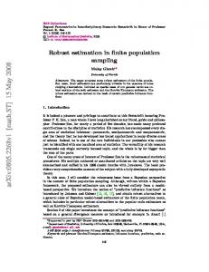
GPUs cannot perform alpha blending on 32-bit floating point textures, so this step is limited to 16 bits of precision. Once the vectors are assigned to histogram bins, we compute a cumulative histogram using Blelloch’s parallel prefix sum algorithm from Section III-A.2. Additionally, since all of these vectors have only two components, we can pack the values from two rows into a single texel and use the GPU’s four-wide vector operators to process both rows at once. Armed with this cumulative histogram, we can now compute the sum over the sliding window with just two or three lookups. Another up-sweep-like reduction is used to find the vector sum with the maximum magnitude, and its orientation is assigned to the corresponding feature. The approximations made in this approach do not impair the accuracy, yielding an RMS error of 0.20 degrees compared to the CPU algorithm. E. Feature Vector Calculation To construct the feature vectors, axis-aligned Haar responses are computed on a 20s × 20s grid, as illustrated in Figure 5. The lattice points of the grid are aligned with the feature orientation, and the Haar response vector is rotated by this angle as well. Each row of the output texture is used to store a single feature vector, with every texel value containing the four elements of v. Normalization is done on the GPU using another simple reduction to compute the vector magnitude. IV. R ESULTS We ran our implementation on a GeForce Go 7950 GTX and a GeForce 8800 GTX using images provided by Mikolajczyk4 as well as several downscaled versions of the frac.pgm image included with SiftGPU [4]. Fig. 6 plots the average 4 http://www.robots.ox.ac.uk/%7Evgg/research/affine/
90 Hz
rates all the way up to HD resolutions, and at SD resolutions on a laptop card. This gives a host of computer vision algorithms the potential to run in real time. In the future, we plan to use new GPGPU APIs such as CUDA or CTM to avoid the graphics pipeline completely, providing additional speedup.
180 Hz 75 Hz 150 Hz 60 Hz 120 Hz 45 Hz 90 Hz
M 100
30 Hz M 100
M 250
60 Hz
M 500 M 250
15 Hz
M 1000
30 Hz
M 500 M 1000
M 2500
M 2500 320´240
640´480
880´680
1280´960
2048´1536
(a) GeForce Go 7950 GTX
320´240
640´480 880´680
1280´960
2048´1536
(b) GeForce 8800 GTX
Fig. 6. Benchmarking results for two GPUs. Isolines for several fixed values of the feature count, M , are interpolated from the measured sample data.
(a) Image 1
(b) Image 2
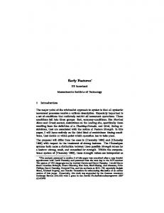
(c) Reconstructed panorama, RMS reprojection error = 0.64 pixels Fig. 7. An example panorama created by matching our SURF features and estimating a homographic projection between images. In this case, 82% of the matches produced by SURF were retained as inliers after RANSAC.
speed of each 10 second run, using thresholds of 1, 21 , and 1 4 for H0 . Our times do not include the time to transfer the image to the graphics card, since this only affects latency, not throughput. On average, we observed the 8800 to be 3.6 times faster than the mobile 7950, even though we performed no specific optimization for it, confining all of our development to 7 Series cards. By comparison, at 640 × 480 SiftGPU runs at 13 Hz on an 8800, and [5] runs at 20 Hz on a QuadroFX 3400. They do not report resulting feature counts, but even at the lowest threshold we tested, we are 3.6 to 5.5 times faster. Although we did not conduct a formal quality comparison with the original SURF algorithm, we achieved very good matching results in our informal testing, as Fig. 7 illustrates. V. C ONCLUSION We have presented a GPU implementation of the SURF feature extraction algorithm that achieves interactive frame
ACKNOWLEDGMENT The authors would like to thank Jared Kresge and Maj. Michael Veth of the Air Force Institute of Technology for their assistance in performance testing. R EFERENCES [1] H. Bay, T. Tuytelaars, and L. V. Gool, “SURF: Speeded up robust features,” in Proc. of the 9th European Conference on Computer Vision (ECCV’06), ser. Lecture Notes in Computer Science, A. Leonardis, H. Bischof, and A. Pinz, Eds., vol. 3951. Graz, Austria: SpringerVerlag, May 2006, pp. 404–417. [2] M. Veth and J. Raquet, “Fusing low-cost image and inertial sensors for passive navigation,” Journal of the Institute of Navigation, vol. 54, no. 1, pp. 11–20, 2007. [3] D. G. Lowe, “Distinctive image features from scale-invariant keypoints,” International Journal of Computer Vision, vol. 60, no. 2, pp. 91–110, Nov. 2004. [4] S. N. Sinha, J.-M. Frahm, M. Pollefeys, and Y. Genc, “GPU-based video feature tracking and matching,” in Proc. of the 2006 Workshop on Edge computing Using New Commodity Architectures (EDGE), Chapel Hill, NC, May 2006. [5] S. Heymann, K. M¨uller, A. Smolic, B. Fr¨ohlich, and T. Wiegand, “SIFT implementation and optimization for general purpose GPU,” in Proc. of the 15th International Conference in Central Europe on Computer Graphics, Visualization, and Computer Vision (WSCG’07), Plzen, Czech Republic, Jan. 2007, pp. 317–322. [6] M. Brown and D. G. Lowe, “Invariant features from interest point groups,” in Proc. of the 13th British Machine Vision Conference (BMVC’02), Cardiff, Wales, Sept. 2002, pp. 253–262. [7] N. K. Govindaraju, E. S. Larsen, J. Gray, and D. Manocha, “A memory model for scientific algorithms on graphics processors,” in Proc. of the ACM/IEEE Conference on Supercomputing (SC’06), no. 89. Tampa, FL: ACM Press, Nov. 2006. [8] F. Zhou and P. Kornerup, “Computing moments by prefix sums,” in Proc. of the IEEE International Conference on Image Processing (ICIP’96), vol. 3, Lausanne, Switzerland, Sept. 1996, pp. 619–622. [9] J. L. T. Cornwall, “Efficient multiple pass, multiple output algorithms on the GPU,” in Proc. of the 2nd European Conference on Visual Media Production (CVMP’05), London, UK, Dec. 2005, pp. 253–262. [10] G. E. Blelloch, “Prefix sums and their applications,” Carnegie Mellon University School of Computer Science, Tech. Rep. CMU-CS-90-190, Nov. 1990. [11] S. Sengupta, A. E. Lefohn, and J. D. Owens, “A work-efficient stepefficient prefix-sum algorithm,” in Proc. of the 2006 Workshop on Edge Computing Using New Commodity Architectures, Chapel Hill, NC, May 2006, pp. D–26–27. [12] D. Horn, GPU Gems 2. Addison Wesley, Mar. 2005, ch. 36, Stream Reduction Operations for GPGPU Applications, pp. 573–589. [13] P. V. Sander, J. R. Isidoro, and J. L. Mitchell, Course Notes for ACM SIGGRAPH 2005 Course 37, 2005, ch. 10. Computation Culling with Explicit Early-Z and Dynamic Flow Control. [14] G. Ziegler, A. Tevs, C. Theobalt, and H.-P. Seidel, “On-the-fly point clouds through histogram pyramids,” in Proc. of the 11th International Fall Workshop on Vision, Modeling, and Visualization (VMV’06), Aachen, Germany, Nov. 2006, pp. 137–144. [15] N. K. Govindaraju, J. Gray, R. Kumar, and D. Manocha, “GPUTeraSort: High performance graphics co-processor sorting for large database management,” in Proc. of the ACM SIGMOD International Conference on Management of Data (SIGMOD’06). Chicago, IL: ACM Press, June 2006, pp. 325–336. [16] T. Scheuermann and J. Hensley, “Efficient histogram generation using scattering on GPUs,” in Proc. of the 2007 Symposium on Interactive 3D Graphics and Games (I3D’07), Seattle, WA, Apr. 2007, pp. 33–37.