GRANADA validation of optimized Multiple Gate. Delay structures for Galileo SinBOC(1,1) signal tracking. Xuan Hu and Elena Simona Lohan. Institute of ...
GRANADA validation of optimized Multiple Gate Delay structures for Galileo SinBOC(1,1) signal tracking Xuan Hu and Elena Simona Lohan Institute of Communications Engineering, Tampere University of Technology P.O.Box 553, FIN-33101, Finland; {xuan.hu, elena-simona.lohan}@tut.fi
Abstract— Multipath is an issue of paramount importance in the GNSS context, and the dominant error source for the Delay Lock Loop (DLL) used for code tracking. This paper introduces an optimized Multiple Gate Delay (MGD) code tracking implementation in the modified GRANADA Bit-true Software Receiver Simulator. Then the tracking performance of the optimized MGD structure is presented via GRANADA simulation results. This tracking performance is also compared with the tracking performance of High Resolution Correlator (HRC) and of the narrow correlator or narrow Early-Minus-Late (nEML) structures. The tracking performance criteria include Multipath Error Envelopes (MEEs) and Root Mean Square Error (RMSE) for both multipath static channels and fading channels. It is shown that the optimized MGD structure has a better performance than nEML and HRC in the multipath channels, and that the GRANADA Bit-true Software Receiver Simulator is a useful tool for testing the performance.
I. I NTRODUCTION Simulation is a powerful method in the analysis and design of communication system. By constructing a simulation model, the performance of the system can be assessed before embarking on building on an engineering model. In the field of testing the CDMA system, several baseband simulators have been generated. For example, for the performance analysis of some CDMA systems, Synopsys COSSAP and CoCentric System Studio simulators have been traditionally used [1]– [3]. However, for testing the performance of Galileo receiver, there are not so many reported simulators available. Many research papers use own models, built in Simulink and Matlab. For example, a Simulink model is used by V. Heiries & al. to test the performance of an enhanced multipath mitigation technique in [4], and by G. Gera & al. in order to investigate the performances of different discriminator used in DLL [5]. In [6], the authors have presented a configurable GPS accumulated in-phase and quadrature-phase signal component simulator built in Simulink. In [7], Binary Offset Carrier (BOC) modulation and code acquisition techniques have been demonstrated by implementing them in a simulator based on Simulink. GRANADA (Galileo Receiver ANAlysis and Design Application) Bit-true Software Receiver simulator [8]–[10] is a Simulink based simulator developed by Deimos Space, for testing the performance of the algorithms applying in
the Galileo receiver. GRANADA simulation was developped within GARDA project, with funds from the European Union, through the Galileo Joint Undertaking (GJU). Because of its high modularity, this simulator has started to be used by several universities and researchers [10]–[13]. For example, J. Diez have presented the characterization of the pseudorange error due to code Doppler shift by using the simulation results from GRANADA Bit-true simulator [10], while an unambiguous delay tracking technique for Galileo Open Service signal was implemented via GRANADA in [13]. In the GNSS receiver, one of the main sources of the error is the multipath propagation via different fading paths. Many papers have presented new code tracking algorithms to cope with this problem. For example, the nEML structure with a narrow correlator spacing [14] of 0.1 chip or smaller for Galileo signals can greatly reduce the tracking error caused by multipath. When another pair of correlators, which correspond to the VE (very early) and VL (very late) branches is introduced, the tracking performance can be improved further. This type of correlator is known as HRC. In the HRC architecture [15], the spacing between the VE and VL correlator is twice the one between the Early (E) and Late (L) correlators. In [13], the authors have presented a so-called Multiple Gate Delay (MGD) structure, which is conceptually close to HRC concept: it uses 4 correlator pairs (with wider correlator spacing than typical HRC), new weighting factors, and some normalization of the discriminator function. However, the tracking performance of MGD in [13] was significantly worse than that of nEML, mainly due to the fact that the weighting factors and the spacings of the MGD correlators were not optimized. In what follows, we have preserved the denomination of MGD in order to refer to delay tracking units with more than 3 correlators (HRC can be seen as a particular case of MGD). However, our proposed MGD differs from that of [13] in several aspects: the weighting factors and correlator spacing is optimized, the number of correlators is increased to 7 (3 early correlators, 3 late correlators and one in-prompt correlator), and the normalization of the discriminator is dropped out, since it showed to give sub-optimal results. The purpose of our paper is two folds: first, we present the optimized MGD structure, by following the steps of the optimization procedure proposed in a recent paper from
Tampere University of Technology [16]. Secondly, we add this MGD structure in the GRANADA Bit-true software receiver simulator, via additional Simulink blocks and we validate the theoretical results via simulations in GRANADA. The novelty of our paper comes from the validation into the GRANADA Bit-true Software Receiver simulator of the optimized MGD delay tracking unit. We also show that the proposed MGD structure has better multipath tracking performance than HRC and nEML.
� Half slot accumulator
BOC
Incoming signal
Chip accumulator
PN code
Data bits
Data accumulator
PR and CF measurements
�
A/D
Acquisition Half slot accumulator
BOC
Chip accumulator
PN code
Data accumulator
Code Tracking DLL
� Half slot accumulator
BOC
Chip accumulator
Carrier Tracking Costas PLL, FLL
PN code
Data accumulator
PLL/FLL output short loop
II. G RANADA ENVIRONMENT DESCRIPTION AND
DLL output
MODIFICATIONS
The GRANADA Bit-true software receiver simulator is a modular and configurable tool, in which different algorithms can be embedded and tested [9], [10], [13]. It implements a dual-channel receiver (data and pilot channel). The whole simulator consists of three blocks, the Galileo transmitter block, the propagation channel block and the Galileo receiver block. The basic block diagram of the GRANADA Bit-true Software Receiver Simulator is shown in Fig. 1, according to [9]. The simulator version we used is V 2.02, and this version was distributed under GJU license agreement.
Fig. 2.
The simplified baseband receiver diagram in GRANADA (nEML)
and Very Very Early (VVE) - Very Very Late (VVL) pair, respectively. The correlator spacings between the E and L branch, the VE and VL branch, the VVE and VVL branch used here are uniformly increasing: ∆, 2∆, and 3∆, respectively (in our implementation we used ∆=0.1 chips, which proved to be, according to simulations, a good tradeoff between stability range and multipath performance for SinBOC(1,1) signals). Non-uniform spacing has also been tested, but it proved to give worse results than the uniform spacing. The 3 branch pairs are combined via a weighted sum, as shown in eq.(1), in order to form the error function e(k) (or the discriminator output): 2 e(k) =a1 · ([IE (k) + Q2E (k)] − [IL2 (k) + Q2L (k)])+
a2 · ([IV2 E (k) + Q2V E (k)] − [IV2 L (k) + Q2V L (k)])+ a3 · ([IV2 V E (k) + Q2V V E (k)] − [IV2 V L (k) + Q2V V L (k)]), (1) Fig. 1. The basic diagram of GRANADA Bit-true software receiver simulator.
The transmitter includes the code generation, BOC modulation, and channel multiplexing. The propagation channel model takes into consideration the multipaths, the Additive White Gaussian Noise (AWGN) and few other possible sources of interference, such as the wideband interference from other satellites. The multipath channel in the simulator consists of a direct path or Line-Of-Sight (LOS) component, which follows a Rice distribution and a maximum of 4 indirect paths or Non-LOS (NLOS) components, which follow a Rayleigh distribution. Both code acquisition and code tracking function are implemented in the receiver block (see Fig. 1). Fig. 2 shows the nEML delay tracking unit implementation of GRANADA. In the nEML receiver there are only three branches: Early (E), Prompt (P), and Late (L) branch. The unmodified GRANADA Bit-true simulator can only support three types of DLL discriminators: EML power, dot product, and EML coherent discriminator, which are explained in detail [14]. All of these DLL discriminator use only 3 branches or correlators. For the optimized MGD structure, three pair of correlators are needed: E-L pair, Very Early (VE) - Very Late (VL) pair,
where I and Q stand for the inphase components and the quadrature components of the chip correlator outputs, k is the time instance, and ai , i = 1, 2, 3 are the weighting factors. As seen in eq.(1), the optimized MGD output is not normalized by the sum of correlator output powers, unlike in [13]. The reason is that this combining rule proved to function better than its normalized version. We also remark that non-coherent combining is used throughout the paper, since non-coherent discriminators are better suited for fading channels and in the presence of small oscillator instabilities than the coherent ones. The weighting parameters ai from the above equation have been optimized according to a minimum area enclosed multipath error envelopes in two-path static channels, following the steps of [16]. The optimization result gave us: (a1 , a2 , a3 ) = (1, −0.7, 0.1).
(2)
We remark that these weights are optimum only for ∆ = 0.1 chip; for other E-L spacings, the procedure must be repeated. Fig. 3 shows the basic diagram of the optimized MGD structure DLL. The loop filter uses a recursive eq.(3), to update the estimated time delay. ǫk stands for the estimated delay value at k-th time instant and γ is the updating parameter in the
III. M ULTIPATH ERROR ENVELOPES AND COMPARISON
a1
E −L
WITH THEORETICAL CURVES
2
a2
VE 2 − VL2
Estimated Delay
+ + +
Loop Filter
a3
VVE − VVL 2
Fig. 3.
2
the diagram of the optimized MGD structure
loop filter (e.g., γ ≈ 0.5 for ∆ = 0.1 chips, according to GRANADA [8]): ǫk+1 = ǫk − γe(k)
(3)
Since the original GRANADA simulator only contains three branches, it can not be used directly to test the performance of the optimized MGD structure DLL. Therefore, the modifications of the GRANADA Bit-true software receiver simulator are necessary, and include two parts, introducing 4 needed branches, shown in Fig. 4 and replacing the original DLL discriminator with the optimized MGD discriminator, shown in Fig. 5.
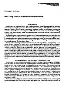
The Multipath Error Envelopes (MEEs) are significant tracking performance criteria for the delay tracking loops in the multipath presence. The value of MEEs is calculated when only direct (LOS) path and one indirect path (NLOS) exists, and the power of indirect path is typically 3 dB less than the direct path. This means the MEEs is calculated when the channel is static. And the maximum errors (positive) and minimum errors (negative) occur when relative indirect path phase is 0 (in-phase) and 180 (out-of-phase) degrees with respect to the direct path [15]. In order to get the MEE value from GRANADA simulation, the ’equivalent low-pass model’ simulation mode, which is one of the simulation modes supported by GRANADA Bittrue simulator, is used to avoid the error caused by the carrier frequency. By deleting the channel fading block and disconnecting PLL output, the MEE simulation result can be obtained. MEE inphase component 15 nEML inphase theoretical nEML inphase simulation result HRC inphase theoretical HRC inphase simulation result Optimized MGD inphase theoretical Optimized MGD inphase simulation result
10
meters
2
5
0
−5
−10
0
0.2
0.4
0.6 0.8 delay of the indircect path (chips) MEE out−of−phase component
1
1.2
1.4
5
meters
0
−5 nEML ouf−of−phase theoretical nEML out−of−phase simulation result HRC ouf−of−phase theoretical HRC out−of−phase simulation result Optimized MGD out−of−phase theoretical Optimized MGD out−of−phase simulation result
−10
−15
Fig. 6.
Fig. 4.
The modified GRANADA receiver block.
Fig. 5.
The modified discriminator in the receiver block.
0
0.2
0.4
0.6 0.8 delay of the indirect path (chips)
1
1.2
1.4
Multipath Error Envelope (inphase and out-of-phase).
The MEE simulation result is calculated by subtracting the mean value of the estimated delay (after it converges) from the estimated delay, when only LOS path exists in the propagation channel. The simulation result of MEE shows an upside-down shape compared with the theoretical one. This is because in GRANADA Bit-true software receiver simulator, the estimated delay is fed back to change the delay of the received signal instead of changing the delay of the local PRN replica sequence (i.e., received signal is sliding with respect to the code, while, typically [15], the code is sliding). In other words, the roles of the received signal and local PRN replica have been exchanged in GRANADA simulator for simplicity reasons. However, this does not influence the results; it is only the sign inversion that should be taken into account. After we change the sign, the simulation result can be compared to the theoretical value, in order to test the validity of GRANADA Bit-true software receiver simulator. Fig. 6 shows both the theoretical MEE and the GRANADA simulation result. The solid lines in Fig. 6 are the theoretical values of the MEE,
The estimated delay of GRANADA simulation −140 GRANADA estimated delay true delay without multipath the mean value of the estimated delay
−142 −144 −146 −148 meters
whereas the circles are the GRANADA simulation results. From Fig. 6, We also see that the GRANADA simulation results match the theoretical value well. And the optimized MGD structure shows the best performance among the narrow EML structure, HRC structure and optimized MGD structure, according to MEE performance criterion. This performance is read as follows: the smaller the enclosed area is, the better the multipath performance is.
−150 −152
IV. ROOT M EAN S QUARE E RRORS
−154
MEEs have however limited generality, since they are computed for static channels alone and in the absence of noise. A more robust performance criterion is the Root Mean Square Error (RMSE) between the estimated delay and the true LOS delay. In order to evaluate the performance of the algorithm in the noise presence, Root Mean Square Errors (RMSE) have been computed. Two scenarios are proposed to test the performance, a static channel and a fading channel, described in Tables I and II. In both scenarios, the multipath propagation channel contains two path, the LOS path and one NLOS path. LOS ray is Rician distributed and NLOS ray is Rayleigh distributed (if fading channel). Table II also shows the relative path delay and path power of NLOS path (we notice that we have very closely-spaced paths). And in GRANADA delay tracking unit, 4 ms coherent integration time is used. TABLE I S IMULATION SCENARIOS . Scenario Scenario 1 Scenario 2
CNR dB/Hz 35,40,45,50 35,40,45,50
−156 −158 −160
0
200
400
600
800
1000
samples
Fig. 7.
Estimated delay from the GRANADA Bit-true simulator.
The RMSE value incorporates both the error bias, which is caused by the multipath component, and the error variance caused by the noise. Fig. 8 shows the RMSE results in the static channel. It reveals that the dominant error source is the multipath. As the CNR increases, the RMSE value converges to the responding value in the MEEs. In the above section, it is shown that the MEEs performance of the optimized MGD structure is always better than other two algorithms. That is also in conformity with the results in the static channel, where the optimized MGD structure also shows best RMSE performance among these three algorithms.
Multipath model static channel fading channel
RMSE in static channel 15 narrow EML structure HRC structure Optimized MGD structure
TABLE II M ULTIPATH RAYS DEFINITION . 10
Delay 0 ns 297 ns (0.3 chip)
Relative Power -100 dB -3 dB
meters
Simulated rays Diffuse component NLOS ray
Fig. 7 shows a snapshot of the estimated delay in the static channel from GRANADA. The conversion between chips and meters is done as follows: d = cτε Tc ,
(4)
where d is the error distance due to a delay error of τε (expressed in chips), c is the light speed and Tc = 0.9775 µs is the Galileo chip interval. For example, an error τε of 0.1 chips would correspond to 29.32 m. In Fig. 7, LOS occurs at about −144 m (with respect to some reference level), and NLOS occurs at about −231 m (the values come again in reverse order, due to GRANADA architecture). The first point at −146 m is the delay estimated by the acquisition stage in the GRANADA. After the acquisition stage, the tracking stage is enabled, and the estimated delay converges to about −155 m error, which is the same as the point in the MEE (i.e., about 11 m apart from the true LOS, as seen in Fig. 6), and oscillates around that point, as seen in Fig. 7.
5
0 35
40
45
50
CNR (dB/Hz)
Fig. 8. RMSE simulation result from the GRANADA Bit-true simulator in static channel
In scenario 2, the RMSE performances are tested. In the propagation channel, the LOS signal has the fixed power and 0 phase error, whereas the gain of the NLOS signal follows Rayleigh distribution and the phase follows uniform distribution in the interval [0, 2π]. Fig. 9 shows the RMSE results in the fading channel. It is clear that the HRC structure improves the performance greatly compared with the nEML structure. The optimized MGD structure shows even better performance than the HRC
RMSE in fading channel 15 narrow EML structure HRC structure Optimized MGD structure
also want to express their thanks to Clemens Buergi from ublox AG, for his useful comments regarding MGD algorithm. R EFERENCES
meters
10
5
0 35
40
45
50
CNR (dB/Hz)
Fig. 9. RMSE simulation result from the GRANADA Bit-true simulator in fading channel
structure. Similar with the static channel situation, the RMSE value of the optimized MGD structure is less than 2 meters when the CNR is 35 dB/Hz. And for CNR values of 50 dB/Hz, the RMSE value of the optimized MGD structure can be reduced to less than 1 meter, which is much better than the other two algorithms. However, the current version of GRANADA Bit-true Software Receiver simulator can only be used to test the performance when the CNR is higher than 35 dB/Hz. If the CNR value is less than 35 dB/Hz, the code acquisition stage is always in process (code delay acquisition is never reached), and the tracking stage in the GRANADA Bit-true Software Receiver cannot be enabled. V. C ONCLUSIONS This paper introduces an optimized MGD delay tracking loop implementation in GRANADA simulation tool and shows that this structure gives better delay tracking results than the narrow correlator and High Resolution Correlator. It is also shown that GRANADA is a flexible simulation tool for Galileo receivers, which allows straightforward modifications in order to test the performance of various delay tracking algorithms. The simulation results were presented for multipath static and fading channels and the performance criteria were the multipath error envelope and root mean square error of the delay estimate. ¿From the simulation results, we can conclude that the optimized MGD structure outperforms the classical nEML and HRC structures and that GRANADA Bit-true software receiver simulator is an useful tool for testing the performance of Galileo receivers. ACKNOWLEDGEMENTS This work was carried out in the project “Galileo Receivers for the mAss market” (GREAT), co-funded by the European GNSS Supervisory Authority (EGSA) with funding from the 6th Framework Programme of the European Community for research and technological development. This work has also been partly supported by the Academy of Finland. The authors
[1] B. Ruiz-Mezcua, A. Gonzalez-Ahijado, and M. Lopez-Carrillo, “Comparison between one and two branches DLL in a CDMA system,” in Vehicular Technology Conference, 1994 IEEE 44th, vol. 1, pp. 559 – 562, June 1994. [2] R. Landry, V. Calmettes, and A. Ducasse, “Impact of Interference on the New COSSAP GPS Receiver and Mitigation Techniques Evaluation ,” in Navigation 2000, January 1998. [3] E. Lohan and M. Renfors., “ Novel adaptive filter for fading channel estimation in coherent CDMA receivers,” in Control, Communications and Signal Processing, 2004. First International Symposium on, pp. 799 – 802, 2004. [4] V. Heiries, D. Rovirasy, V. Calmettes, and L. Ries, “ An Enhanced Correlation Processing Multipath Mitigation Technique for BOC Signals,” in Position, Location, And Navigation Symposium, 2006 IEEE/ION, pp. 342 – 347, 2006. [5] G. Gera and C. S. Regazzoni, “ A new method for performance enhancement of tracking modules in a multipath environment for satellite based navigation systems ,” in 14th International Technical Meeting of the Satellite Division of the Institute of Navigation (ION GPS 2001), pp. 2161–2165, 2001. [6] P. Corbell and M. Miller, “A Configurable GPS Accumulated I and Q Signal Component Simulator in Matlab,” in Proc. of ION NTM, 2001. [7] N. Martin, V. Leblond, G. Guillotel, and V. Heiries, “BOC(x,y) Signal Acquisition Techniques and Performances,” in Proc. of ION GPS, 2003. [8] “GRANADA, Galileo receiver analysis and design applications.” http://www.deimos-space.com/granada. [9] A. Fernandez, J. Diez, L.Marradi, and Vincent.Gabaglio, “Galileo Receiver performance under GPS interference and multipath with the GRANADA Software Receiver,” in Proc. of ION GNSS, Sep 2004. [10] J. Diez, A. Fernandez, J. S. Silva, L.Marradi, and V. Gabaglio, “Characterization of the Pseudorange Error Due to Code Doppler Shift in Galileo E5 and L1 Receivers Using the GRANADA Bit-True Simulator,” in Proc. of ION GNSS, 2005. [11] P. Kovar, F. Vejrazka, L. Seidl, and P. Kacmarick, “Galileo receiver core technologies,” Journal of Global Positioning Systems, vol. 4, no. 1–2, pp. 176–183, 2005. [12] J. Won, T. Pany, and G. Hein, “GNSS software defined radio: real receiver or just a tool for experts,” Inside GNSS, pp. 48–56, Jul/Aug 2006. [13] D. de Castro, J. Diez, and A. Fernandez, “A New Unambiguous LowComplexity BOC Tracking Technique,” in Proc. of ION GNSS, 2006. [14] A. van Dierendock, P. Fenton, and T. Ford, “Theory and Performance of Narrow Correlator Spacing in a GPS Receiver,” Navigation, pp. 265– 283, 1992. [15] G. McGraw and M. Braasch, “GNSS Multipath Mitigation Using Gated and High Resolution Correlator Concepts,” in Proc. of ION NTM, 1999. [16] D. Skournetou and E. Lohan, “Non-coherent multiple correlator delay structures and their tracking performance for Galileo signals,” in ENCGNSS, 2007.