J. Rossignac. Brush as a walkthrough system for ar- chitectural models. Fifth, 1996. [42] William J. Schroeder, Jonathan A. Zarge, and. William E. Lorensen.
Graphics Pipeline for Interactive Visualization of Very Large 3D Models S. P. Mudur, Dinesh Shikhare and Deepraj Dixit Graphics & CAD Division, National Centre for Software Technology, Juhu, Mumbai 400049, India. mudur,dinesh,dixit @ncst.ernet.in �
Abstract In this paper we present a graphics pipeline for interactive rendering of very large models such as architectural data, engineering models, GIS terrain geometry and data obtained by 3D range scanners. Our pipelined architecture covers acquisition of the data, healing of models, storage and transmission schemes and handling rendering of and interaction with such models having many million triangles. We also classify the reported techniques based on the characteristics of the models and present our own architecture for a virtual walk-through of large models.
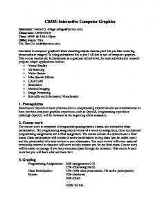
1 Introduction Recent years have seen increasing use of large 3D models in various application domains such as engineering design and manufacture, architecture, medical imaging, GIS, art restoration studies and heritage site documentation. Virtual walk-throughs of architectural and power plant models deploy data having tens of million polygons defining the geometry. In addition these data often have rich textures, associated non-visual information and behaviours such as dynamically changing geometries, reponse to interactions, etc. Laser range scanners are being used to obtain detailed 3D models consisting of many million triangles. Visual inspection of such large models involves achieving a real-time performance for interactive rendering. GIS applications have terrain data and associated information which is often huge and requires specialised techniques for achieving interactive rendering speeds. The sheer size and complexity of these models pose many challenges in effectively utilising them in interactive graphics applications. Figure 1 identifies these challeges in the form of a pipeline that has evolved through the applications we have developed and studied. In this paper, we identify the problems faced in each stage of this pipeline
Creation of Model
Acquisition of model (semi−automatic or manual)
Pre−processing Stage
Run−time Processing
Storage scheme
Healing of model
Rendering Integration of Model
Application specific data processing
Run−time database scheme Interactions
Acquisition of Motion, Animation, Behaviour.
Transmission scheme
Figure 1: Graphics pipeline for large models and discuss various approaches to solve them. Each stage in the pipeline is significantly affected by the characteristics of the model at hand and of course the endgoal of the application. However, irrespective of the process used for acquiring the geometry and attributes data, the common characteristics found in the raw data are: (a) the geometry is usually represented as a soup of polygons, (b) there is no hierarchical structure in the model, (c) the data may have degenerate geometric/topological features such as gaps, overlaps, duplicated geometry, hidden geometry, etc. These problems in the raw data must be healed to make the data suitable for use in the ultimate application. Usually the 3D model is transformed into a format that is suitable for the application. The data format may then be further transformed for compressed storage, encrypted or watermarked for the protection of intellectual property rights, or may be stored for a progressive transmission and eventual rendering. At run-time, the processing carried out by the rendering engine is typically based on frametime budget determined by the desired frame-rate. The per-frame computation typically involves decisions about selection of level-of-detail of the model, computation of dynamic geometries, detection of collisions, interactions like selection, feedback, and so on. To facilitate interactive
Creation of Model
Acquisition of model (semi−automatic or manual)
3D scaning Photogrammetry Modeling tools
Acquisition of Motion, Animation, Behaviour.
Healing of model Removal of duplicate geometry slivers, holes gaps
Integration of model
Fixing texture map errors
3D motion capture Modeling of animation Removal of jitter, jerkiness, etc.
Association of geometry, attributes and dynamic behaviours.
Figure 2: Creation of large models frame-rates and efficient handling of response to user interactions special run-time database organization schemes are needed. These schemes support specific algorithms for visibility culling, collision detection and response, and so on. Based on our studies, we have encountered two kinds of large models: (a) Those having a few connected components (very often a single mesh) formed by dense collection of large number of polygons. Notable examples are Stanford Bunny having over 50,000 triangles, the statue of David from the Digital Michelangelo project defined with millions of triangles. A special case of such models is seen in the form of terrain data which is also very dense, but is a height-field data. (b) Those consisting of a large number of meshes, each defined by upto a few hundred triangles. Examples of such models are large architectural models, complex power plant models, etc. We have seen that the set of techniques needed at various stages of the pipeline are different for these two different types of models. In the following sections, we describe the stages of the pipelined graphics architecture for handling large models.
2 Creation of Large Models Preparation of 3D geometry content and associated data for interactive applications has been known to be a laborious task. Besides the difficulties faced in obtaining sources of information required for modeling the content, the technological issues of creating the model pose challenges. These challenges are (a) selection of suitable tools for manually creating models or semi-automatically scanning models, (b) representation of the large data generated in acquiring the model to make it suitable for the application, (c) detection of errors in the model and correction (also called healing), and (d) integration of the model data to establish association among the various media elements such as geometry, texture images, video, sound and animation. In this section we outline various techniques used for
Figure 3: A part of Diwan-i-Khaas palace of Fatehpur Sikri – the entire model is defined using 2.5 million triangles and 25 megabytes of textures. acquiring and conditioning data for interactive visualization applications needing large models. Figure 2 outlines the problems addressed during the creation of models.
2.1 Acquisition Techniques Depending on the kind of model to be acquired, different tools are used. Architectural and machine models are modeled using modeling tools like AutoCAD, 3D Studio, etc. The output of such tools is typically a collection of polygon meshes along with texture maps. The interactions used to create parts of the model include: extrusion, sweep, boolean operations between solids, inclusion of pre-defined components from library of well known standard models. A part of a complex model created using AutoCAD and 3D Studio is shown in Figure 3. This model is a part of Fatehpur Sikri walkthrough project [1] carried out at NCST. Textures for such models are obtained by scanning pictures of the real models or by creating the textures in image editing tools. A 3D modeling tool is then used to define texture mapping scheme for generation of texture coordinates for the model. This process is extremely labour intesive, however, it is also the most commonly employed technique for the creation of large models. Typically many designers collectively create a large model over a period of time. This often leads to inconsistencies in the model and errors in data. These errors must be painstaking corrected if there are no automated model validation and healing tools.
To obtain 3D models of sculptures and complex curved artifacts some researchers have used laser range imaging scanner. The range images are typically formed by sweeping a 1D or 2D sensor linearly across an object or circularly around it (see figure 4). Object Direction of Scan
Laser Sheet
CCD image
Collection of Scanned Points
Cylindrical Lens Laser
CCD
(a)
(b)
Figure 4: 3D scanning process: (a) at a given position of the scanner, a sequence of depth values are measured, (b) using a sequence of such points, a triangulation is created with a regular structure. The regular structure of scanned points is utilised to generate a regular connectivity triangulation of the scanned surface. To completely capture the details of an object, multiple range images must be obtained from various camera poses. Each such range image gives a triangle mesh. Such meshes captured from many camera poses are then merged or stitched together to create a single 3D triangle mesh model (see [51] for a stitching algorithm). With the improvement in the resolution and accuracy of the scanners many huge models have been created. While the detailed models serve as an authentic record of the 3D objects, they tend to be extremely large for storage and transmission. Mark Levoy et al worked on acquisition of very detailed models in their Digital Michelangelo project [35]. The enormous models digitized for the project include 10 statues from two buildings adding up to 2 billion polygons and 7000 images. The statue of David alone consumes 32 gigabytes of data in captured geometry. Similar work has been reported as a part of IBM’s Pieta Project for scanning detailed 3D models. Recently Bernardini and Rushmeier presented their 3D model acquisition pipeline [9] to capture large amount of data.
2.2
Healing of Large Models
The models acquired using various techniques are not always directly usable in the applications without significant transformations. There is always a mismatch between
the raw acquired data and the form in which it is needed for eventual use. The mismatch could be found in the following different ways: 1. Data formats: The modeling packages often have their own proprietary data formats for storing the 3D models created. The format primarily used by a particular package usually captures all features of the construction tools and procedures with high fidelity. The end-applications, however, often require these models in a different file format as well as in terms of different data entities. For example, a versatile NURBS modeling package may be used to design surface geometry of a 3D object. For using the 3D object in a visualization package, one would have to tessellate these models into triangulated surfaces. This leads to approximations inherent to the discretization process. Various “neutral” file formats exist for CAD data exchange – IGES, STEP , etc. Modelers for architectural geometry like AutoCAD, 3D animation packages like 3DStudio Max, Alias Wavefront, SoftImage have their own proprietary file formats. Translation of models across data formats is a significant mismatch problem. 2. Lack of structure in the data: In many cases the geometry data is organized as a “soup of polygons” [5]. Handling such data for geometry manipulation is extremely difficult because of lack of structure and grouping definition. A healing package must give a structure to such a geometry by looking for a coherent structure in the unstructured 3D data. 3. Gaps, holes and T-junctions: 3D models described using polygon meshes can have topological insanities like gaps between two meshes attempting to represent an object with closed surfaces. Such gaps/holes in the data can cause errors in simulation programs such global illumination computation by radiosity methods [6]. T-junctions create topological holes in models defined using multiple surface components. Topological surgery is required to correct such problems in the geometry. 4. “Invisible” geometry: There are many different situations when parts of the modeled geometry is not visible due to the following reasons: (a) Unused vertices, (b) Dangling edges and (c) Hidden polygons. This invisible geometry does not contribute in useful manner to the end application, but poses combinatorial overhead to the computation. 5. Excess detail: Either due to the data acquisition process or content creator’s preference, excessive details are captured for models which can be described using much less data. Excess level of detail affects the performance of data visualizers, walk-through programs etc. Many approaches exist for reducing the details of the meshes by way geometry simplification [42, 29] and topology simplification [19]. 6. Overlapping geometry: Probably the most difficult ge-
ometry insanity to handle is that of overlapping geometry. Completely duplicated geometry can be trivially eliminated. But partial geometric overlap between two surfaces requires trimming of surfaces are some arbitrary point of contact between the surfaces. handling this automatically is difficult, but interactive manipulation by expert user is feasible. 7. Volume of data: With increasing usage of 3D content over the Internet and increase in the complexity of the digital models, special techniques for compression of geometry data have become important. Various topological and geometric encoding methods [17, 29, 40] have been explored by researchers for achieving high compression ratios.
2.3
Modeling of Dynamic Behaviour
Capturing dynamic behaviour of 3D models has been a challenging problem. By dynamic behaviours we mean the following kinds of characteristics in the model: (a) non-interactive: fixed animations performed by transforming geometry, and (b) interactive: change in geometry, attributes or animations based on interactive user input. The fixed animations are usually straight-forward to implement in a model, since they need to be statically stored with the model and played back on demand while visualizing the mdoel. For example the animation of ripples and waves in animated water implemented in Fatehpur Sikri project [1] has a pre-determined animation associated with the geometry (a triangle mesh). The animation is computed on fixed intervals to update the geometry of the model and rendered on demand. An interactively influenced change in the geometry of the model has been implemented using very sophisticated techniques for handling deformations of geometric models [8, 24]. We discuss detection of collision and response in Section 6.
2.4
Integration of Model
Usually the various activities like modeling of geometry, modeling of dynamic behaviour, creation of other media elements like images, textures, audio, video are carried out using independent tools and different environments. Integration of all these media elements into a single interactive visualization application is a necessary task in the pipeline. This stage of development involves sub-tasks like: (a) association of animations with geometric models, (b) spatial and heirarchical placements of media elements for the desired visual experience, and (c) defining temporal association between the behaviour and geometric models. Mostly the requirements of integration are vastly different with respect to different applications. The planning of the integration scheme has largely been ad hoc in the applications we studied [1, 2]. However it is hard to anticipate the requirements of all future visualization systems
Data to be associated with model for accelerating rendering
Data to be associated with model for visual realism
Pre−processing Stage LoDs Simplification Visibility map
Storage scheme
Illumination Shadows
Application specific data processing
Geometry compression Relationship with associated data File format / Directory structure for database
Run−time database scheme
Collision map Event map Application specific data for triggering response to interactions
Transmission scheme
Progressive geometry representation IPR issues encryption watermarking
Figure 5: Application specific pre-processing for large models and develop a system for facilitating integration of multiple kinds of media elements for interactive visualization.
3 Application Specific Preprocessing Allowing user to interactively navigate through the 3D model is one of the basic objective of most graphics visualization applications. There is a need to maintain a steady and interactive frame rate while rendering 3D models to avoid flicker and eye fatigue. Very large models pose a challenge in this respect, even to high-end graphics rendering systems such as SGI Infinite Reality Engine. Moreover the model sizes are increasing faster than hardware rendering capabilities. Thus there is a continuous need for innovative algorithmic techniques to accelerate rendering of large and complex 3D models. Many techniques which accelerate the rendering of complex scenes and enhance the quality of visualization, especially for very large models, rely on the preprocessing of the model data. These techniques use involved and ingenious data structures appropriate for the specific model data at hand. The large model data is preprocessed to extract this kind of data. Such data structures can be braodly classified into three catagories based on their effective use in the rendering phase. These catagories are shown in Figure 5 as associted with preprocessing stage. First are those which are directly used to accelerate the rendering. Typical examples are generation of level-of-details and selection of large occluders for occlusion culling at run time. Second class of data organizations partition the large model space for efficient query processing. For example, cell based partition of the model can created to help trigger associated media activation events in an architectural walkthrough. The last class of model preprocessing is to directly contribute to the enhanced experience of the user. A typical example is to perform global illumination on the model.
In following subsections we describe main kinds of data organizations which are generated as a part of preprocessing phase.
3.1
Accelerating Rendering
There are two basic principles behind various algorithmic approaches trying to accelerate frame-rate and achieve interactive rendering speeds: 1. Do not even attempt to render any geometry that the user will not ultimately see. 2. Render geometry in just enough detail to be correctly from user view point. As all these techniques have some runtime component, we will only briefly mention various techniques here. Refer to Section 5 for more detailed description of these techniques. Techniques based on the first principle, called visibility culling, include set of techniques like view frustum culling, back-face culling, and occlusion culling. Occlusion culling attempts to remove objects which are occluded by objects in the front based on the current viewpoint. To perform this test efficiently at runtime, specialized data organizations (priority lists) or large occluders are used. Such informations is derived from the model data at preprocessing time. Techniques based on second principle can be further classified into either multi-resolution meshes or image based rendering techniques. In multi-resolution mesh (also known as level-of-details) approach, progressively simplified versions of large and/or complex mesh are precomputed. At rendering time, based on certain view-dependent parameters, appropriate level of detail mesh representation is choosen. In image based rendering techniques, a large part of model is substituted by an image which is textured on a simple geometry primitive. This technique is also known as “imposters”. In specific applications like architectural environments walkthroughs, the model structure can be effectively exploited to make use of such imposter images in place of door and window openings, called “portals”. This technique has shown good speedups, but suffers from parallax problems (see [44]).
3.2
Enabling Responses
Many graphics applications providing visualizing capabilities for large models need to provide various interactions over and above basic view manipulation capabilities. A typical heritage architectural walkthrough application may need to start an audio explaining significance of an intricate structure the user is currently viewing, or an mechanical CAD product inspection application may need to provide details of a tiny part in an complex assembly. Such interactions pose another level of challenge when dealing
with very large models. Most such interactions and media triggers are based on few basic queries for collision detection, distance computation and visibility tests. The inherent structure of the model is typically used to provide fast responses to such proximity and visibility queries. Media associations are stored in some kinds of 2D or 3D maps which mimic the form of model. These methods are far from automatic and are applicable only to specific model types. A number of general algorithms have been proposed for performing proximity and visibility queries on geometric models. Typically, bounding volume hierarchies are used to accelerate these queries. Axis aligned bounding boxes are simplest, but recently proposed Oriented bounding boxes, k-DOPs and spherical shells are much tighter fitting to objects and perform much better. One drawback of these techniques is the considerable storage requirements, which may become unacceptable for very large models. Wilson et. al. present a new data structure called overlap graph which exploits the locality of computation to perform proximity queries at interactive speeds on massive models with small memory footprint.
3.3 Enhancing Visualization Smooth navigation capabilities with interactive framerate is one (although an important one) of the factor in providing good walkthrough experience. Another one is accurate illumination of the model. To achieve high-quality rendering of the model, global illumination techniques are used. Though these are notoriously famous for their slowness, techniques like radiosity and partical tracing are view-independent and can be carried out as a preprocessing step. Generated illumination in the form of color properties of the vertices can be fed to the Z-buffer based rendering engine at runtime. Even as a preprocessing step, the large models present a challenge to these techniques.
4 Storage and Transmission The large size of the data representing 3D models affects their access in two major ways: (a) the models require a huge storage space, and (b) it takes a long time to load the models in memory for further processing such as rendering, illumination computation, etc. For these reasons many researchers have rigorously explored the areas of compression and progressive transmission of 3D models.
4.1 Compact Storage A large amount of research on compression of geometry has concentrated on models that consist of very few large triangle meshes representing manifold. The class of models made up of a large number of small meshes has been largely unexplored by the graphics community so far for compression.
Initial interest in compression of geometry arose out of need for minimising the data sent to rendering pipe. The ideas implemented in 3D drawing toolkits like OpenGL [52] are triangle strips and triangle fans. The compaction is achieved by avoiding the use of repeated references to vertices for connected polygons. Longer the triangle strips, higher is the utilization of the bandwidth of the rendering hardware. Optimizing the triangle strips of a mesh for fast rendering has been studied extensively [21]. The ideas were restricted to triangle strips and triangle fans until Deering’s paper [17] introduced generalized triangle meshes by defining operators to encode the traversal over the triangles in the mesh. Strategies for compression of meshes broadly belong to the following classes: (a) graph traversal based decomposition of meshes, (b) quantization of geometry and attributes for lossy compression, (c) use of predictors for compacting the dynamic range of values to be encoded, and (d) signal processing approach for compression of geometry. Most of the reported works combine multiple strategies to achieve compressed storage of 3D models. Large body of geometry compression research has concentrated on clever encoding of the connectivity among the vertices in the mesh. These encodings seek to minimize and localize the repeated references to vertices, thereby achieving a compact description of the mesh. The number of triangles is roughly twice the number of vertices and each vertex is referenced in 5 to 7 triangles, which shows that large part of the representation of the model is the definition of connectivity among the vertices. This observation has encouraged a lot of work to develop schemes to minimize the repeated references to vertices. Many researchers [40, 48, 50, 26, 32] have published detailed strategies based on graph traversal. The connectivity is typically encoded as traversal of the graph of as spanning trees of vertices and the spanning trees of polygons (the dual). Each scheme uses some traversal of the graph while encoding the steps in the path to unambiguously reconstruct the original connectivity. The geometry and the attributes are predictively coded by taking advantage of the the coherence between the successive positions in the traversal. In most of the architectural models we worked with the meshes have texture maps. In order to capture different mapping coordinates at vertex positions shared by two polygons, the vertices are repeated. Due to this condition of the data the graph traversals referred above do not work very well and cause a large overhead. Besides compactly encoding the connectivity, almost all published work reports schemes for compression of geometry and attributes. Deering [17] used quantization of the coordinate values from 32 bits to 16 bits, use of 9-bit in-
dex into a global list of values for normals and a 15 bit representation of colour values. Quantization of coordinates and colour values leads to an indiscriminate truncation of the accuracy regardless of the features in the geometric models. Predictive encoders perform much better by taking advantage of the coherence in the data to predict the value of the next element in the sequence. Depending on the condition of the data and the characteristics of the predictor the prediction errors vary. Predictors can be designed so that most error values are small and only a few are large. These error values can then be quantized effectively and then entropy coded for compact representation. Signal processing based techniques have been in use for handling triangle mesh data for applications such as surface fairing [45], multiresolution analysis [27]. These techniques are based on construction of a set of basis functions for decomposition of the a triangle mesh into signals. These signals have components across a spectrum of frequences. The low frequency components in the signals correspond to smooth features in meshes and high frequency components correspond to discontinuities in the meshes such as creases, folds and corners. Karni and Gottsman [33] proposed a spectral compression technique for triangle mesh data. For spectral decomposition of the mesh geometry, they construct a set of orthonormal basis functions from the connectivity relationship within the mesh. For smooth meshes, the high frequency components of these spectra will have very insignificant values, which can either be truncated or be quantized among a small number of discrete values. This provides a novel geometry compression idea which can be employed with any connectivity compression scheme. This compression scheme is analogous to the JPEG image compression algorithm that decomposes the discrete image signal in terms of coefficients of cosine basis functions.
4.2 Transmission of Models Deployment of large models in collaborative environments requires transmission of models over networked workstations in a LAN and over the Internet. The limited bandwidths of communication among the cooperating elements have motivated research in progressive transmission of 3D models. Sharing of complex models over the insecure communication media has raised concerns of copyrights and intellectual property rights in deploying models created by incurring a large cost. 4.2.1 Progressive transmission Progressive transmission of geometric models aims to trasmit a coarse representation of the model first and subsequently transmit the details to refine it. Compression
strategies have been used in the progressive representation of models to also make the entire transmission data compact. Many groups have developed compression schemes incorporating progressive transmission capabilities. Pajarola and Rossignac [38] have extended Hoppe’s Progressive Meshes [29] to obtain a compressed representation. Cohen-Or et al [13] have created a vertex decimation based triangle mesh hierarchy for simplification and refinement of models. Progressive transmission of the model is achieved by first sending the coarse simplified model, followed by information for reconstructing the original model. The vertex insertion details are encoded compactly to achieve compression. Taubin et al [47] discuss their scheme for compression and progressive transmission of clustered multi-resolution meshes. In progressive forest split compression by Taubin et. al. [46] a manifold triangle mesh is also represented as a low resolution polygonal model followed by a sequence of refinement operations. The forest split operation, which can be seen as a grouping of several consecutive edge split operations into a set instead of a single large sequence, provides tradeoff between compression ratio and granularity. The schemes that combine compression and progressive transmission always have a tradeoff between compression and additional data to be used for progressive representation of the models.
4.2.2 Intellectual property rights The initial solution to the problem of ensuring copyrights and restricted access was through encryption of models using encryption algorithms. However the onus of protecting the encryption keys and ensuring that the decrypted model is not stolen is on the consumers of the model. Watermarking provides a mechanism for copyright protection of digital media by embedding information identifying the owner in the data. Robust watermarking must be able to survive a variety of “attacks”, including resizing, croping and filtering. For ownership claims, watermarks encode the fact that the document was created by the owner. To be effective, the watermark scheme must minimise the probability of false-positive results – incorrectly asserting that a document in watermarked when it is not. To decrease the probability of false-positive claims, the watermark is usually encoded in the document using vector coefficients. This vector is compared to that observed in the suspect document and the ownership claim is based on their statistical correlation. Many researchers have recently presented schemes for robust watermarking of dense 3D meshes [39, 7].
Run−time Processing Imposters Visibility culling LoD selection Frame−rate budget
Rendering Run−time database scheme
Camera
Change of view
Partitioning of Interactions model for on−demand Collision detection change of loading and response model Texture 3D picking management Event driven media activation Association between geometry and application specific data such as collision maps and event maps
Figure 6: Run-time processing for interactive visualization
5 Rendering These steps which form the apex of the graphics pipeline are the most affected by the large size and complexity of the model data. These steps form the runtime portion of the graphics pipeline. As the rendering speed is very important to end users, the performance of these steps is crucial in deciding the success of the entire project/program. As discussed in previous Section 3, many of the techniques which aim to improve rendering performance, build extensive data structures by pre-processing the 3D model. For very large models, a single technique rarely suffices. The combination of techniques to be used to achive better performance depends on the model characteristics, user priorities of the performance parameters and the effective utilization of the available resources. In this section we outline such techniques used for inteactive visualization of large models.
5.1 Visibility Culling Visibility culling techniques try to send a graphics primitive to rendering pipeline only if it has any impact on the display. If the object is outside view frustum (view culling), facing away from the view point (backface culling) or occluded by objects (occlusion culling) these techniques cull the object. A great amount of work has been done in both Computer Graphics [54] and Computational Geometry [16]. A typical attempt to solve visibility problem uses hierachical occlusion maps [55], an object-space bounding volume hierarchy and another hierarchy of image-space occlusion maps. For each frame, a set of objects from a
pre-computed database is choosen to be occluders and are used to cull geometry. Other similar work is hierarchical Z-buffer [25], and object space visibility culling [49], [15].
5.2
LoD Selection
Complex objects which are far away or small can be substituted by their simplified versions to speed up the rendering process. Generally these techniques approximate the complex object by its simpler variations termed levels-of-details (LoDs). The LoDs can be generated statically with or without human assistance [18]. There also have been some attempts to generate the LoDs on the fly [30] and generating view-dependent simplification of the meshed models [53]. Slightly older, but still a good overview of the polygonal model simplification methods is given by Carl Erikson [20].
5.3
Image Based Rendering
The idea of replacing a 3D model by a rendered image can be traced back to the idea of environment maps [10]. Their direct application to the rendering was used by Chen and Williams using range images [12]. This approach allowed limited motion around a viewpoint by using prerendered images of the scene. More involved approaches include the use of panaromic images used in QuicktimeVR [11] and plenoptic modelling [37]. Maciel and Shirley [36] introduced idea of image “imposters”. In their work, a hierarchy of a 3D complex model is created; on the faces of bounding boxes images of the cluster contents are created. These images are used in place of box contents when this representation is judged sufficient. In other approaches [43] images of distant scenery are cached and replace complex geometry based on image discrepancy criteria. The idea of representing 3D scenes as a light field or lumigraph was presented by [34] and [23], respectively, where scene geometry complexity is relatively unimportant and projections of this representation are extracted to generate images.
5.4
Frame-rate Budget
As the advances in graphics hardware has not been able to keep pace with the size and complexity of the models, various new algorithms have evolved to render the geometry in the approximate form. Such algorithms trade the quality of the rendered image with the time required to render it. With such a choice of techniques forming the spectrum on the output frame rate, a concept of rendering frame rate budget has evolved. The target frame rate is decided first. Then to achieve and maintain it, a set of techniques are chosen automatically by the system. If there is less amount of time per frame, heavy use of imposters is made. Even while rendering nearby geometry the choice of LoDs and the rendering order of polygons is driven by the target frame rate.
Such methods are good in sustaining the frame rates. As noted by [22] maintaining a near constant frame rate in walkthrough systems, which may not be very high, is important. The time per frame is allocated to various tasks need to be performed in the system, including prefetching and rendering. The rendering time is further allocated to rendering distant objects using fast rendering technique (typically image based) and rest is spent in rendering nearby visible geometry using LoD. For very large models, even this filtered model cannot be directly rendered using hardware. Specific ordering of neighbouring polygons X proposed in [14] maximizes the likelihood of rendering visible polygons before occluded ones for any given scene.
6 Interactions Apart from the basic view manipulation, i.e., walkthough, user may interact with the model in various form. In walkthrough applications, user expects to collide with rigid structures in the path, while in model inspections, user needs capabilities to pick and query associated information. Grabbing and manipulating virtual objects is an important user interaction for immersive virtual environments. Dynamic object behaviors play a significant role in enhancing the realistic and immersive experience of the user. Such behaviors also provide valuable clues about model characteristics to the user which are not apparant from visual inspection alone. In cultural heritage site walkthroughs, informative audio-visuals which are not triggered directly by the user are very useful. Following subsections provide more insight into some major problems faced while providing such end-user interactions when dealing with large to model data.
6.1 Collision Detection The most important of the interaction problem that needs to be addressed is the collision detection, which arises in various form in many applications. In architectural walkthroughs, the navigator is generally constrained not to walk through the walls and similar rigid structures to enhance realism. In virtual and immersive environments, which are used for model creation and design reviews, interactive and direct manipulation of virtual objects needs to be supported. Such a functionality effectively uses interference detection and distance computation. As described earlier, various forms of bounding volume hierarchies are used to accelerate these queries when dealing with large models. These hierachies are built from the model in the preprocessing stage. Though this precomputation reduces runtime overhead of collision detection substantially, the method works well only for static model. A method presented by Wilson et. al., addresses this issue to some extent. In their system Immpact, they handle
dynamic environments by modifying precomputed hierarchies on the fly by taking advantage of spatial and temporal coherence.
6.2
Picking and Manipulation in 3D
There are variety of existing techniques which attempt to solve the problem of picking and manipulating remote objects in (immersive) visualisations of large models. In non-immersive visualisations, the pointer on the image plane is used to pick the projected object. This is a natural extension of the desktop pick. In immersive virtual environments, the problem is tougher to solve. Two common methods used are arm-extension and ray-casting. In armextension technique, user’s virtual arm is made to grow to the desired length. Though the manipulations using virtual hand are easy, grabbing object may be difficult if the object is small of far. In ray-casting technique, virtual light ray is used to grab the object. Then the case is exactly reversed. There have been some attempts to create some hybrid methods having benefits from both techniques. In spite of the interface provided, the actual processing of the pick query remains a challenge for large models. This typically amounts to some form of ray object intersection. Common techniques to accelerate such operations like, simplified bounding objects and cached list of visible objects are used. For very large models such data structures are hierarchically maintained. Such hierarchies are similar to or even same as, the hierarchies used for accelerating collision detection.
7 Management of Run-time Data The huge amount of data associated with very large models to be visualized interactively poses a difficult problem of database management. The large amount of data is present in the form of geometry, textures, pre-computed data for the acceleration of interactions, rendering, enhancement of visual quality, etc. All of the data cannot be loaded in the main memory at a given time. To handle the large run-time database for these applications, elaborate schemes have been designed [2]. The main memory as well as the texture memory must be managed in order to optimally utilize the resources of the given hardware. Budgeting of each type of memory must also be done to ensure that the operating system does not incur too many page faults in accessing the huge runtime data loaded in the virtual memory. An equivalent of demand paging done in operating systems is required in case of the large models and their associated data. This requires a partitioning scheme for decomposing the model into parts that are loaded on demand. The decomposition schemes are typically hierarchical in nature. These hierarchies could be spatial or object-based. To achieve efficient management of the run-time database, a large amount of pre-processing of the large
model is done to build an associated database of occluders, LoDs, imposters, visibility sets and event-based media activation maps.
8 Integrated Systems Where as each algorithmic technique so far discussed by itself reduces the number of rendered primitives, no one technique suffices for interactive walkthroughs of the most large models. Moreoverm each technique achieves great speedups only for particular subsets of primitives. Any general system for interactive walkthroughs needs to integrate many such techniques. One such framework for walkthrough of very large model 3D model is [3]. They have proposed an integrated framework which describe database representation, present an effective pipeline to manage all system resources and demonstrate the system on a massive model of coal-fired power plant consisting of 15 million triangles. They have reported speedups ranging from 50 to 100 times by integrating multiple techniques [4]. Several industrial vendors, including Silicon Graphics and Hewlett-Packard have proposed architectures and APIs for interactive display of large CAD models [28], [31]. The BRUSH system [41] developed at IBM, provides an interactive environment for the real-time visualization and inspection of very large mechanical CAD (and architectural) model.
References [1] Fatehpur Sikri: An epic in red sandstone, 1999. NCST, Mumbai, India. (http://www.ncst.ernet.in/fatehpur). [2] A. Aliaga, J. Cohen, A. Wilson, H. Zhang, C. Erikson, K. Hoff, T. Hudson, W Stuerzlinger, E Baker, R. Bastos, M. Witton, F. Brooks, and D. Manocha. A framework for the real-time walkthrough of massive models. Technical Report UNC TR98-013, University of North Carolina at Chapel Hill, 1998. [3] D. Aliaga, J. Cohen, A. Wilson, H. Zhang, C. Erikson, K. Hoff, T. Hudson, W. Stuerzlinger, E. Baker, R. Bastos, M. Whitton, F. Brooks, and D. Manocha. A framework for the real-time walkthrough of massive models. Technical Report TR98-013, UNC– Chappel Hill, 1998. [4] D. Aliaga, J. Cohen, H. Zhang, R. Bastos, T. Hudson, and C. Erikson. Power plant walkthrough: An integrated system for massive model rendering. Technical Report TR97-018, UNC–Chappel Hill, 1997. [5] Gill Barequet, Christian Duncan, and Subodh Kumar. RSVP: A geometric toolkit for controlled repair of
solid models. IEEE Transactions on Visualization and Computer Graphics, 4(2), April-June 1999.
[17] Michael Deering. Geometry compression. In SIGGRAPH’95 Proc., pages 13–22, 1995.
[6] D. Baum, S. Mann, K. Smith, and J. Winget. Making radiosity usable: Automatic preprocessing and meshing techniques for the generation of accurate radiosity solutions. In SIGGRAPH’91 Proc., pages 51–60, Aug. 1991.
[18] Matthias Eck, Tony DeRose, Tom Duchamp, Hugues Hoppe, Michael Lounsbery, and Werner Stuetzle. Multiresolution analysis of arbitrary meshes. Proceedings of SIGGRAPH 95, pages 173–182, August 1995. ISBN 0-201-84776-0. Held in Los Angeles, California.
[7] O. Benedens. Geometry-based watermarking of 3D models. IEEE Computer Graphics & Applications, January 1999. [8] G. Bergen. Collision detection of complex deformable models using aabb trees. Journal of Graphics Tools, 1(7):1–13, 1997. [9] F. Bernardini and H. Rushmeier. The 3d model acquisition pipeline. In Eurographics 2000 State of the Art Report (STAR), 2000. [10] J. F. Blinn and M. E. Newell. Texture and reflection in computer generated images. Communications of the ACM, 1976. [11] Shenchang Eric Chen. Quicktime vr - an image-based approach to virtual environment navigation. Proceedings of SIGGRAPH 95, pages 29–38, August 1995. ISBN 0-201-84776-0. Held in Los Angeles, California. [12] Shenchang Eric Chen and Lance Williams. View interpolation for image synthesis. Proceedings of SIGGRAPH 93, pages 279–288, August 1993. ISBN 0201-58889-7. Held in Anaheim, California. [13] D. Cohen-Or, D. Levin, and O. Remez. Progressive compression of arbitrary triangle meshes. In Visualization’99 conference proceedings, pages 67–72, 1999. [14] Jo˜ao Comba, James T. Klosowski, Nelson Max, Joseph S. B. Mitchell, Cl´audio T. Silva, and Peter L. Williams. Fast polyhedral cell sorting for interactive rendering of unstructured grids. Computer Graphics Forum, 18(3):369–376, September 1999. ISSN 10677055. [15] S. Coorg and S. Teller. A spatially and temporally coherent object space visibility algorithm. Technical Report TM-546, Laboratory of Computer Science, MIT, 1996. [16] M. de Berg, M. van Kreveld, M. Overmars, and O. Schwarzkopf. Computational Geometry. Springer-Verlag, Berlin, 1997.
[19] Jihad El-Sana and Amitabh Varshney. Topology simplification for polygonal virtual environments. IEEE Transactions on Visualization and Computer Graphics, 4(2), April-June 1998. [20] Carl Erikson. Polygonal simplification: An overview. Technical Report TR96-016, UNC–Chappel Hill, 1996. [21] F. Evans, S. S. Skiena, and A. Varshney. Optimizing triangle strips for fast rendering. In Visualization’96 Conference Proceedings, pages 319–326, 1996. [22] T. A. Funkhouser. Database and Display Algorithms for Interactive Visualization of Architecture Models. PhD thesis, CS Division, University of California Berkeley, 1993. [23] Steven J. Gortler, Radek Grzeszczuk, Richard Szeliski, and Michael F. Cohen. The lumigraph. Proceedings of SIGGRAPH 96, pages 43–54, August 1996. ISBN 0-201-94800-1. Held in New Orleans, Louisiana. [24] S. Gottschalk, M. C. Lin, and D. Manocha. OBBTree: A hierarchical structure for rapid interference detection. In SIGGRAPH’96 Proc., 1996. [25] N. Greene, M. Kass, and G. Miller. Hierarchical zbuffer visibility. In SIGGRAPH 93 Conference Proceedings, pages 231–240. ACM, August 1993. [26] Stefan Gumhold and Wolfgang Strasser. Real-time compression of triangle mesh connectivity. In Proceeding of ACM SIGGRAPH, pages 133–140, July 1998. [27] I. Guskov, W. Sweldens, and P. Schroeder. Multiresolution signal processing for meshes. In Proceeding of ACM SIGGRAPH, pages 325–334, 1999. [28] Hewlett-Packard. Hp direct model. http://hpcc920.external.hp.com/ wsg/products/grfx/ dmodel/index.html, 1997. [29] Hugues Hoppe. Progressive meshes. In SIGGRAPH’96 Proc., pages 99–108, Aug. 1996.
[30] Hugues Hoppe. View-dependent refinement of progressive meshes. Proceedings of SIGGRAPH 97, pages 189–198, August 1997. ISBN 0-89791-896-7. Held in Los Angeles, California.
[42] William J. Schroeder, Jonathan A. Zarge, and William E. Lorensen. Decimation of triangle meshes. Computer Graphics (SIGGRAPH’92 Proc.), 26(2):65–70, July 1992.
[31] Silicon Graphics Inc. Sgi opengl optimizer. http://www.sgi.com/software/optimizer/, 1997.
[43] Jonathan Shade, Dani Lischinski, David Salesin, Tony DeRose, and John Snyder. Hierarchical image caching for accelerated walkthroughs of complex environments. Proceedings of SIGGRAPH 96, pages 75–82, August 1996. ISBN 0-201-94800-1. Held in New Orleans, Louisiana.
[32] Martin Isenbueg and Jack Snoeyink. Face Fixer: Compressing polygon meshes with properties. In Proceeding of ACM SIGGRAPH, 2000. [33] Z. Karni and C. Gotsman. Spectral compression of mesh geometry. In Proceeding of ACM SIGGRAPH, 2000. [34] Marc Levoy and Pat Hanrahan. Light field rendering. Proceedings of SIGGRAPH 96, pages 31–42, August 1996. ISBN 0-201-94800-1. Held in New Orleans, Louisiana. [35] Marc Levoy, Kari Pulli, Szymon Rusinkiewicz, David Koller, Lucas Pereira, Matt Ginzton, Sean Anderson, James Davis, and Jeremy Ginsberg. The Digital Michelangelo Project: 3D scanning of large statues. In SIGGRAPH 2000 Proceedings., 2000. [36] Paulo Maciel and Peter Shirley. Visual navigation of large environments using textured clusters. Symposium of Interactive 3D Graphics, pages 95–102, April 1995. [37] Leonard McMillan and Gary Bishop. Plenoptic modeling: An image-based rendering system. Proceedings of SIGGRAPH 95, pages 39–46, August 1995. ISBN 0-201-84776-0. Held in Los Angeles, California. [38] Renato Pajarola and Jarek Rossignac. Compressed progressive meshes. Report GIT-GVU-99-05, GVU Center, Georgia Tech., Atlanta, USA, 1999. [39] Emil Praun, Hugues Hoppe, and Adam Finkelstein. Robust mesh watermarking. In SIGGRAPH ’99 Proc., Aug. 1999.
[44] Franc¸ois X. Sillion, G. Drettakis, and B. Bodelet. Efficient impostor manipulationfor real-time visualization of urban scenery. Computer Graphics Forum, 16(3):207–218, August 1997. ISSN 1067-7055. [45] Gabriel Taubin. A signal processing approach to fair surface design. In Proceeding of ACM SIGGRAPH, pages 351–358, 1995. [46] Gabriel Taubin, Andre Gueziec, William Horn, and Francis Lazarus. Progressive forest split compression. In Proceeding of ACM SIGGRAPH, July 1998. [47] Gabriel Taubin, William Horn, and Paul Borrel. Compression and transmission of multiresolution clustered meshes. Technical Report RC21398(96630)2FEB1999, IBM T.J. Watson Research Centre, New York, USA, 1999. [48] Gabriel Taubin and Jarek Rossignac. Geometry compression through topological surgery. ACM Transactions on Graphics, 17(2):84–115, April 1998. [49] S. Teller and C. Se´quin. Visibility processing for interactive walkthroughs. In SIGGRAPH 91 Conference Proceedings, pages 61–69. ACM, July 1991. [50] Costa Touma and Craig Gotsman. Triangle mesh compression. In Proceeding of Graphics Interface ’98, June 1998. [51] Greg Turk and Mark Levoy. Zippered polygon meshes from range images. In Proceeding of ACM SIGGRAPH, pages 311–318, 1994.
[40] Jarek Rossignac. Edgebreaker: Connectivity compression for triangle meshes. IEEE Transactions on Visualization and Computer Graphics, 5(1):47–61, January-March 1998.
[52] M. Woo, J. Neider, and T. Davis. OpenGL Programming Guide. Addison-Wesley Publishing Company, 1996.
[41] B. Schnieder, P. Borrel, J. Menon, J. Mittleman, and J. Rossignac. Brush as a walkthrough system for architectural models. Fifth, 1996.
[53] J. Xia and A. Varshney. Dynamic view-dependent simplification for polygonal models. IEEE Visualization, 1996.
[54] H. Zhang. Effective Ocllusion Culling for the Interactive Display of Arbitrary Models. PhD thesis, Department of Computer Science, University of North Carolina, Chappl Hill, 1998. [55] H. Zhang, D. Manocha, T. Hudson, and K. Hoff III. Visibility culling using hierarchical ocllusion maps. In SIGGRAPH 97 Conference Proceedings, pages 77–88. ACM, August 1997.