and Installation Practices for Electronic Sirens. Used on Law Enforcement
Vehicles. NIJ Guide 500–00. Randall Wagner. Acoustics, Mass, and Vibrations
Group.
U.S. Department of Justice Office of Justice Programs National Institute of Justice
National Institute of Justice Law Enforcement and Corrections Standards and Testing Program
Guide to Test Methods, Performance Requirements, and Installation Practices for Electronic Sirens Used on Law Enforcement Vehicles NIJ Guide 500–00
ABOUT THE LAW ENFORCEMENT AND CORRECTIONS STANDARDS AND TESTING PROGRAM The Law Enforcement and Corrections Standards and Testing Program is sponsored by the Office of Science and Technology of the National Institute of Justice (NIJ), U.S. Department of Justice. The program responds to the mandate of the Justice System Improvement Act of 1979, which directed NIJ to encourage research and development to improve the criminal justice system and to disseminate the results to Federal, State, and local agencies. The Law Enforcement and Corrections Standards and Testing Program is an ap plied research effort that determines the technological needs of justice system agencies, sets minimum performance standards for specific devices, tests commercially available equipment against those standards, and disseminates the standards and the test results to criminal justice agencies nationally and internationally. The program operates through: The Law Enforcement and Corrections Technology Advisory Council (LECTAC), consisting of nationally recognized criminal justice practitioners from Federal, State, and local agencies, which assesses technological needs and sets priorities for research programs and items to be evaluated and tested. The Office of Law Enforcement Standards (OLES) at the National Institute of Standards and Technology, which develops voluntary national performance standards for compliance testing to ensure that individual items of equipment are suitable for use by criminal justice agencies. The standards are based upon laboratory testing and evaluation of representative samples of each item of equipment to determine the key attributes, develop test methods, and establish minimum performance requirements for each essential attribute. In addition to the highly technical standards, OLES also produces technical reports and user guidelines that explain in nontechnical terms the capabilities of available equipment. The National Law Enforcement and Corrections Technology Center (NLECTC), operated by a grantee, which supervises a national compliance testing program conducted by independent laboratories. The standards developed by OLES serve as performance benchmarks against which commercial equipment is measured. The facilities, personnel, and testing capabilities of the independent laboratories are evaluated by OLES prior to testing each item of equipment, and OLES helps the NLECTC staff review and analyze data. Test results are published in Equipment Performance Reports designed to help justice system procurement officials make informed purchasing decisions. Publications are available at no charge through the National Law Enforcement and Corrections Technology Center. Some documents are also available online through the Internet/World Wide Web. To request a document or additional information, call 800–248–2742 or 301–519–5060, or write: National Law Enforcement and Corrections Technology Center P.O. Box 1160 Rockville, MD 20849 –1160 E-Mail:
[email protected] World Wide Web address: http://www.nlectc.org
The National Institute of Justice is a component of the Office of Justice Programs, which also includes the Bureau of Justice Assistance, the Bureau of Justice Statistics, the Office of Juvenile Justice and Delinquency Prevention, and the Office for Victims of Crime.
U.S. Department of Justice Office of Justice Programs National Institute of Justice
Guide to Test Methods, Performance Requirements, and Installation Practices for Electronic Sirens Used on Law Enforcement Vehicles NIJ Guide 500–00
Randall Wagner Acoustics, Mass, and Vibrations Group National Institute of Standards and Technology Gaithersburg, MD 20899–8221
Coordination by: Office of Law Enforcement Standards National Institute of Standards and Technology Gaithersburg, MD 20899–8102
Prepared for: National Institute of Justice Office of Science and Technology Washington, DC 20531
August 2000
NCJ 181622
National Institute of Justice
Julie E. Samuels Acting Director
The technical effort to develop this guide was conducted under Interagency Agreement 94–IJ–R–004 Project No. 96–10IA–CTT.
This guide was prepared by the Office of Law Enforcement Standards (OLES) of the National Institute of Standards and Technology (NIST) under the direction of James A. Worthey, Program Manager for Information Technology and Communication Systems, and Kathleen M. Higgins, Director of OLES. The work resulting in this guide was sponsored by the National Institute of Justice, David G. Boyd, Director, Office of Science and Technology.
FOREWORD The Office of Law Enforcement Standards (OLES) of the National Institute of Standards and Technology (NIST) furnishes technical support to the National Institute of Justice (NIJ) program to strengthen law enforcement and criminal justice in the United States. OLES's function is to conduct research that will assist law enforcement and criminal justice agencies in the selection and procurement of quality equipment. OLES is: (1) Subjecting existing equipment to laboratory testing and evaluation, and (2) conducting research leading to the development of several series of documents, including national standards, user guides, and technical reports. This document covers research conducted by OLES under the sponsorship of NIJ. Additional reports as well as other documents are being issued under the OLES program in the areas of protective clothing and equipment, communications systems, emergency equipment, investigative aids, security systems, vehicles, weapons, and analytical techniques and standard reference materials used by the forensic community. Technical comments and suggestions concerning this document are invited from all interested parties. They may be addressed to the Office of Law Enforcement Standards, National Institute of Standards and Technology, Stop 8102, Gaithersburg, MD 20899–8102. David G. Boyd, Director Office of Science and Technology National Institute of Justice
iii
CONTENTS FOREWORD.............................................................................................................................iii COMMONLY USED SYMBOLS AND ABBREVIATIONS....................................................vi 1. INTRODUCTION...............................................................................................................1 2. BASIC CHARACTERISTICS AND SPECIAL FEATURES OF ELECTRONIC SIRENS......................................................................................................2 3. DOCUMENTS THAT SPECIFY SIREN TESTS, PERFORMANCE REQUIREMENTS, AND INSTALLATION PRACTICES.................................................3 4. LABORATORY MEASUREMENTS AND SIREN PERFORMANCE...............................4 5. SIREN INSTALLATION.................................................................................................... 7 5.1 Options .......................................................................................................................7 5.2 Installation Practices Recommended or Required by Siren Documents ........................8 6. TECHNICAL DETAILS CONCERNING TEST PROCEDURES, MEASUREMENT INSTRUMENTATION, AND PERFORMANCE REQUIREMENTS SPECIFIED IN SIREN DOCUMENTS........................................................................................................9 APPENIDX A–OCCUPATIONAL HEARING LOSS AND EXPOSURE TO SIREN NOISE............................................................................................................ 18 APPENDIX B–REFERENCES................................................................................................. 20 APPENDIX C–INFORMATION REQUIRED TO CONTACT ORGANIZATIONS LISTED IN THIS GUIDE...............................................................................22
TABLES Table 1. Documents that specify test methods, performance requirements, and installation practices for emergency vehicle sirens ......................................................3 Table 2. Additional tests required for siren components ............................................................7 Table 3. Relative response levels for A-weighting at se lected frequencies ...............................10 Table 4. Standardized averaging time settings available on sound level meters and other acoustical measurement instruments ................................................................. 11 Table 5. Frequency and cycle rate requirements for wail .........................................................14 Table 6. Frequency and cycle rate requirements fo r yelp .........................................................15 Table 7. Minimum requirements for the maximum A-weighted sound pressure level (in dB re 20 µPa) produced by a siren system under test during any portion of its cycle.................................................................................................................16 Table 8. Minimum requirements for the minimum A-weighted sound pressure level (in dB re 20 µPa) produced by a siren system under test during any portion of its cycle.................................................................................................................17 Table 9. A-weighted time-weighted average (TWA) noise sound pressure level (SPL, in dB re 20 µPa) limits (not to be equaled or exceeded) recommended by NIOSH ..............18
FIGURE Figure 1. Examples of wail and yelp with cycle rates of 20 cycles per minute ( cpm) and 240 cpm, respectively ................................................................................................13 v
COMMONLY USED SYMBOLS AND ABBREVIATIONS A ac AM cd cm CP c/s d dB dc °C °F dia emf eq F fc fig. FM ft ft/s g g gr
ampere alternating current amplitude modulation candela centimeter chemically pure cycle per second day decibel direct current degree Celsius degree Fahrenheit diameter electromotive force equation farad footcandle figure frequency modulation foot foot per second acceleration gram grain
H h hf Hz i.d. in IR J L L lb lbf lbf·in lm ln log M m min mm mph m/s N N·m
henry hour high frequency hertz inside diameter inch infrared joule lambert liter pound pound-force pound-force inch lumen logarithm (base e) logarithm (base 10) molar meter minute millimeter miles per hour meter per second newton newton meter
nm No. o.d. Ω p. Pa pe pp. ppm qt rad rf rh s SD sec. SWR uhf UV V vhf W λ wt
area=unit 2 (e.g., ft2, in 2, etc.); volume=unit 3 (e.g., ft3, m3, etc.) PREFIXES d c m µ n p
deci (10 -1) centi (10 -2) milli (10 -3) micro (10 -6) nano (10-9) pico (10-12)
da h k M G T
deka (10) hecto (102) kilo (10 3) mega (10 6) giga (10 9) tera ( 1012)
COMMON CONVERSIONS (See ASTM E380) 0.30480 m =1ft 2.54 cm = 1 in 0.4535924 kg = 1 lb 0.06479891g = 1gr 0.9463529 L = 1 qt 3600000 J = 1 kW·hr
4.448222 N = lbf 1.355818 J =1 ft lbf 0.1129848 N m = lbf in 14.59390 N/m =1 lbf/ft 6894.757 Pa = 1 lbf/in 2 1.609344 km/h = mph
Temperature: T?C = (T?F-32)×5/9 Temperature: T?F = (T?C×9/5)+32
vi
nanometer number outside diameter ohm page pascal probable error pages parts per million quart radian radio frequency relative humidity second standard deviation section standing wave ratio ultrahigh frequency ultraviolet volt very high frequency watt wavelength weight
NIJ GUIDE 500–00
GUIDE TO TEST METHODS, PERFORMANCE REQUIREMENTS, AND INSTALLATION PRACTICES FOR ELECTRONIC SIRENS USED ON LAW ENFORCEMENT VEHICLES1
1. INTRODUCTION Sirens are devices that produce warning sounds. Siren sounds are intended to help alert the public that an emergency vehicle (e.g., police car, ambulance, fire truck) is nearby and responding to an emergency. These sounds should be recognized as the call for the right-of-way of the vehicle. There are three types of emergency vehicle sirens: electronic, mechanical, and electromechanical. Mechanical and electromechanical sirens are powered by a mechanical connection to the vehicle drive train or an electric motor. These sirens produce sound by pumping air through a perforated disk revolving in front of a fixed structure with ports. As the disk turns, the perforations pulse the air flow through the ports. The successive pulses of air produce the familiar mechanical siren sound, which modulates in frequency and amplitude as the disk and air flow speed up, and slow down. An electronic siren is a system of components that includes one or two electronic siren loudspeakers (seldom more than two) and an electronic siren amplifier powered by the vehicle electrical system. Most sirens sold for law enforcement vehicles are electronic. The size of most electronic siren loudspeakers permits them to fit in smaller spaces than mechanical and electromechanical sirens. This guide is written for persons who select, install, or operate electronic sirens on law enforcement vehicles, or instruct those who do. It discusses the contents of several documents, listed later in the guide, that specify test methods, performance requirements and installation practices for electronic siren systems. The goal is to familiarize law enforcement personnel with these documents and the meaning of compliance with each one. Apart from this issue, the basic characteristics of electronic siren systems are discussed, as well as special features and installation
1
No approval or endorsement by the National Institute of Standards and Technology (NIST) or the author, of any company or commercial product, is intended or implied. Any mention of commercial product features or accessories in this NIJ guide does not imply recommendation or endorsement by NIST or the author, of such features, products that provide such features, or related accessories. Users of this document should consult applicable State and local laws and regulations. The author and NIST do not intend to suggest action that is not in compliance with applicable laws, and this document may not be construed as doing so. This guide is not meant to replace manuals supplied by equipment manufacturers and should not be used for such a purpose.
1
options. The related issues of occupational hearing loss and exposure to siren noise are also addressed. All of the material presented in the first five sections of the guide is fairly basic in nature. Technical details are limited to section 6.
2. BASIC CHARACTERISTICS AND SPECIAL FEATURES OF ELECTRONIC SIRENS Two widely used and recognized sounds are available with electronic siren systems sold in the United States. A wail is designed to mimic the intrinsic sound of a mechanical siren. This sound is produced by slow increases and decreases in frequency. A yelp cycles through a range of frequencies in a manner similar to a wail, but at a faster cycle rate. Other sounds, less commonly used, are available with many siren systems. Most siren systems also have a so-called manual control on the amplifier, which is a momentary contact switch that permits intermittent, rather than continuous, operation. All electronic siren sounds originate as an electrical signal produced by the siren amplifier. The electrical signal is converted into sound by a compression driver, which is part of the electronic siren loudspeaker. Other loudspeaker parts, such as re-entrant tips and projectors, direct and radiate the sound. Beyond their ability to produce the common warning sounds, many siren systems have additional features, which may be inherent, optional, or provided through accessories. Features and accessories available with some commercial siren systems include: ! ! ! ! ! ! ! ! ! ! ! ! ! ! !
Shuts off when the vehicle is shifted into park. Includes various levels of warning light controls. Will not turn on unless the warning lights are turned on; the siren and warning lights can be turned on with a single switch. Turns on only by selecting a siren function; there is no on/off switch. Controls are included that allow brake and back-up lights to be deactivated. Adjustable lighting for siren controls that is independent of the siren power. Microphone jack for a plug-in microphone instead of a hard-wired microphone. Turns off if a short-circuit, or over/under-voltage are detected. Siren and light controls are located on a hand-held microphone. Some functions can be selected using a vehicle horn or foot switch. Public address capability for a microphone input. Public address capability for a one- or two-way radio. Self-diagnostic indicator of an amplifier or loudspeaker failure. Manual control that can be programmed to sound only while it is depressed or for a given duration after it is depressed. Siren is disabled if a lamp in the lightbar circuit fails.
2
!
Combination siren/light control with an audible annunciator that indicates the warning lights are on.
Advertising literature often comments on the types of controls, size of controls and control markings, clarity of markings, how well lit the controls are, etc. By making the amplifier easier to use, such features may help the driver to simultaneously operate the siren and drive safely and effectively during an emergency. 3. DOCUMENTS THAT SPECIFY SIREN TESTS, PERFORMANCE REQUIREMENTS, AND INSTALLATION PRACTICES In the United States, the most widely recognized and cited documents that specify test methods, performance requirements, and installation practices for emergency vehicle sirens are those listed in table 1. Information required to contact the organization that produced each document is given in appendix C. Table 1. Documents that specify test methods, performance requirements, and installation practices for emergency vehicle sirens Description
Abbreviated description used in this guide
Section 3.14.6 of the Federal specification KKK–A–1822[1] for ambulances, produced by the U.S. General Services Administration (GSA).
GSA K-Specification
Title 13, Article 8 of the California Code of Regulations[2] (CCR), produced by the California Highway Patrol.
CCR Title 13
Emergency Vehicle Sirens-SAE J1849 August 1995 Recommended Practice[3], produced by the Society of Automotive Engineers (SAE).
SAE J1849
The General Services Administration (GSA) K-Specification is a comprehensive specification that describes ambulances authorized to display the “Star of Life” symbol. Minimum specifications, test parameters, and essential criteria for ambulance design, performance, equipment, and appearance are established in order to provide a practical degree of standardization. The goal is to afford national recognition to ambulances that function reliably during emergency medical service and are easily maintained.
3
The Federal Government is not the only user of the GSA K-Specification. Many State and local governments and private sector purchasers require certification of ambulances to this specification. No such comprehensive private or Federal standard or specification exists for certifying police vehicles and the equipment used on them. An established siren certification program currently exists for the GSA K-Specification. It is managed by the Automotive Manufacturers Equipment Compliance Agency (AMECA), a private independent certification agency, which accredits test laboratories, reviews data, and lists approved siren systems. Information required to contact AMECA is given in appendix C. The California Highway Patrol (CHP) developed the California Code of Regulations (CCR) Title 13 over many years [4].2 Established certification programs once managed by the CHP and AMECA for CCR Title 13 have been discontinued. However, CCR Title 13 and many of its test methods and performance requirements are still widely recognized within the law enforcement community and the emergency vehicle siren industry. This California document was used as a model to produce the Society of Automotive Engineers (SAE) J1849 recommended practice and is cited by the GSA K-Specification for some of its test methods and performance requirements. The SAE Emergency Warning Devices Standards Committee, which is currently active, developed SAE J1849 and is in the process of updating this recommended practice. It is cited by the National Fire Protection Association (NFPA) 1901 Standard for Automotive Fire Apparatus [5] (Sec. 9-9 on audible warning devices), which is used for certification of fire trucks. There are no independent agencies or certification programs that certify laboratories for SAE J1849 tests or list siren systems in compliance with its requirements. 4. LABORATORY MEASUREMENTS AND SIREN PERFORMANCE Results of siren measurements depend not only on the characteristics of the siren components tested, but also on the test procedures and the characteristics of the measurement instrumentation and test environment. These additional factors must be well defined and controlled and their effects on the measurement results understood, for correct interpretation of results and proper assessment of siren performance. An implicit concern in all of the siren documents is that the siren sound must be loud enough to warn effectively. In order to address this concern, these documents require sound pressure level3 (SPL) measurements. Loudness depends on SPL and frequency. At any given frequency, loudness generally increases as the SPL increases. To help account for the frequency dependence, most sound level meters and other acoustical measurement instruments can calculate weighted
2
Numbers in brackets refer to references in appendix B.
3
All sound pressure levels in this guide were calculated using a reference sound pressure of 20 micropascals (20 µPa). See section 6 for details.
4
levels by applying standard frequency weightings [6,7] to a measured SPL. The GSA KSpecification, CCR Title 13, and SAE J1849 dictate that a specific standard frequency weighting, known as A-weighting, be used to measure the SPL produced by a siren loudspeaker. Technical details concerning A-weighting, and other factors that the measured SPL is dependent on, are discussed in section 6. These factors include the averaging time set on the measurement instrumentation, and the distance between the siren loudspeaker and the measurement microphone. Another factor is the amount of time the siren has been operating, since the SPL produced by a siren begins to decrease after it begins operation. The GSA K-Specification, CCR Title 13, and SAE J1849 require the measurement of the Aweighted SPL on the device axis. This axis passes through the center of, and is parallel to the direction faced by, the siren loudspeaker, or multiple siren loudspeaker system. Since sirens need to be heard by motorists approaching intersections on cross-streets, A-weighted SPL measurements are also required by CCR Title 13 and SAE J1849 at positions off the device axis. No performance requirements are included in the GSA K-Specification for any locations off the device axis. Another note concerning this GSA document is that it requires tests of siren systems with dual loudspeakers. Results obtained using a loudspeaker pair do not reliably indicate the performance of only one of the loudspeakers. The GSA K-Specification, CCR Title 13, and SAE J1849 all require that sirens be tested in anechoic chambers. These chambers provide an environment with acoustical properties that are controlled and reproducible. Reflections of sound are minimized in anechoic chambers by sound absorptive material on the inner surfaces, and there is also isolation from external acoustical noise and vibration. In addition, the ambient relative humidity and temperature, which affect sound propagation, are better controlled in an indoor laboratory environment, such as an anechoic chamber. These factors help provide acoustical measurement results that are repeatable and accurate. Measurement results obtained under controlled laboratory conditions are necessary in order to qualify the performance of all sirens as equally as practicable. Whether a person will hear, recognize, and react quickly enough to the warning sounds produced by a siren during an emergency depends on many factors in addition to the SPL it produces in a controlled test environment. Reflection, scattering and attenuation caused by objects such as buildings, trees, road surfaces, and other vehicles, contribute to sound propagation losses. Absorption of sound by the atmosphere itself also results in losses. Windows, soundproofing, and other materials on a vehicle further decrease sound levels. Background noise interferes with hearing, an effect called masking. Siren sounds are masked by traffic and community noise, and noise produced by radios, air conditioning, wind, and rain. There are also variations in how well different people can detect, identify, and localize sounds, which are partly due to their ability to hear as a function
5
of frequency. Finally, how effectively someone can react to a detected sound depends on the proximity and speed of the emergency vehicle, the speed of their vehicle, and their reflexes. Emergency vehicle sirens do not produce sounds that are loud enough to warn effectively in all circumstances. There is no assurance that all other motorists will always hear, recognize, or react quickly enough to the warning sounds produced by a siren to take appropriate action. It is necessary for emergency vehicle operators to watch for the reaction of other motorists to the siren and be prepared to maneuver accordingly. A report prepared for the U.S. Department of Transportation by Bolt, Beranek, and Newman Inc., concluded that the sound levels produced by sirens would have to be increased greatly, to the point where these levels would be intolerable to the community, in order to be loud enough to warn effectively in all ordinary circumstances [8]. Manufacturers sell siren systems that produce sounds in addition to the wail and yelp, such as the hi-lo, hyper-yelp, pulsar, phaser, simulated air horn, etc. However, CCR Title 13, the GSA KSpecification, and SAE J1849 provide performance requirements for wail and yelp only. Other sounds are not required to be tested, even if they are produced by a siren system. Siren sounds other than wail and yelp are actually prohibited by CCR Title 13 from being included with siren systems in California. All sounds other than yelp, wail, or a wail produced with the manual control are defined in SAE J1849 as auxiliary signals (sounds). This SAE document recommends that auxiliary sounds be used only in nonemergency situations, and not as a call for the right-ofway of an emergency vehicle. A test of the manual control is required by CCR Title 13 and the GSA K-Specification, but not by SAE J1849. Only siren systems, not individual siren components, are allowed to be tested and approved according to CCR Title 13 and the GSA K-Specification. Any siren loudspeaker or amplifier that is stated to have met the requirements of either document must have a specific amplifier or loudspeaker model with which it was matched to pass the tests. Approved siren systems contain components that are usually well matched with respect to frequency to maximize the SPL output, often by adjusting the amplifier to dwell longest in a frequency range that includes the loudspeaker resonance frequency. Systems created by combining components from two different systems that meet these requirements are not approved and cannot be assumed to meet all requirements since the components are not necessarily matched to maximize the loudspeaker SPL output. The August 1995 version of SAE J1849 includes tests that allow for siren components to be approved separately. However, these tests do not provide adequate assurance that a system, created from a loudspeaker and amplifier approved separately, could meet the SAE J1849 acoustical performance requirements for a system. Technical details concerning acoustical test procedures and performance requirements specified in the GSA K-Specification, CCR Title 13, and SAE J1849 are given in section 6. In addition to the acoustical tests, there are other types of tests required by these documents to qualify emergency vehicle sirens. Table 2 lists these additional tests and indicates the particular tests required by each document.
6
Table 2. Additional tests required for siren components Test
CCR Title 13
SAE J1849
GSA K-Specification
Electrical power
Yes
Yes
Yes
Electrical voltage
No
Yes
No
High temperature
No
Yes
Yes
Low temperature
No
Yes
Yes
Durability
No
Yes
No
Vibration
No
Yes
No
Moisture
No
Yes
No
Dust
No
Yes
No
Corrosion
No
Yes
No
Amplifier public address mode
No
No
Yes
5. SIREN INSTALLATION 5.1 Options Installation options for electronic siren components may be limited by the make, model, and year of the vehicle intended to be equipped. Limitations are often due to a lack of appropriate mounting surfaces or space for the siren components, vehicle components that obstruct the loudspeaker opening, or other equipment that limits access to siren controls. Siren amplifiers can be configured as a control panel (control head) and a remote power amplifier, which can be mounted separately, or a single integrated unit that combines the control and power sections. Both flush and surface mounted control panels can be bought for use with remote power amplifiers. Consoles that fit between the front seats of vehicles for mounting siren amplifiers and other equipment can also be purchased. Pedestal mounts are available for handheld microphones sold with siren amplifiers. Some mounts are sold that can be configured in multiple positions. Electronic siren loudspeakers are available that mount behind the front grille; on, under, or behind the front bumper; in a light bar grille; or on a push bumper. Some loudspeaker systems can be bought with the compression driver connected to the loudspeaker horn via a flexible tube, which allows the driver and horn to be mounted a limited distance apart. For push bumper mounting, additional brackets and support braces are sold for supporting the loudspeaker weight. Push 7
bumper support braces can be obtained with pre-drilled holes for mounting particular siren loudspeakers. Installation of motor vehicle aftermarket products, such as push bumpers or siren components, can potentially create a safety hazard or interfere with vehicle systems. For example, siren amplifiers mounted in the airbag deployment zone can become dangerous projectiles during deployment. It is advisable to follow all instructions and safety precautions provided by manufacturers of motor vehicles and aftermarket products in order to minimize the potential for problems due to interactions between systems. 5.2 Installation Practices Recommended or Required by Siren Documents Several general guidelines and recommendations for siren installation are provided in SAE J1849. In addition, it points out that siren performance relies on proper installation, as does safe vehicle operation during an emergency. This SAE document states that the installation should limit as much as practical the noise level in the passenger compartment of the vehicle, allow siren operation without loss of eye contact with the roadway or excessive movement away from the seat back, and not reduce the acoustical performance of the siren system. To minimize the risk of hearing loss, SAE J1849 recommends that the maximum sound pressure level in the passenger area when the vehicle is in motion with the siren operating, not exceed an A-weighted SPL of 85 dB. In order to verify sound levels in the passenger area, this SAE document recommends that manufacturers and users of emergency vehicles should measure the actual sound pressure levels at each riding position. For the recommended sound levels to be achieved, SAE J1849 states that electronic siren loudspeakers should be installed at locations as far from the occupants as possible, such as the front bumper, using acoustically insulated compartments and isolation mountings to minimize the transmission of sound into the vehicle. Heavily insulating the passenger compartment and operating the siren only with the windows closed are suggested. However, SAE J1849 points out that a siren loudspeaker mounted on the front of a vehicle could have its performance reduced by road slush (snow, sleet, mud, etc.), or incur damage more easily in minor collisions. This SAE document also indicates that heavily insulated passenger compartments and closed windows may result in an inability to hear the sirens on other emergency vehicles. Therefore, training of vehicle operators to alert them to these problems is also recommended by SAE J1849. In order to not significantly reduce the acoustical performance of a siren loudspeaker, SAE J1849 recommends that the sound projecting opening should be pointed forward, parallel to the ground, and not obstructed or muffled by structural components of the vehicle. For this reason, concealed or under hood mounting of siren loudspeakers is not recommended by SAE J1849. Several identification codes for siren components, which indicate the general location where a particular component should be mounted, are specified in SAE J1849. It recommends that all devices should be mounted in accordance with this code and the manufacturer’s instructions, and 8
securely fastened to vehicle elements of sufficient strength to withstand the forces applied to the device. The codes are EVS1 for interior, trunk, or other dry compartment mounting; EVS2 for outside the vehicle; and EVS3 for under hood mounting. Ambulances certified to the GSA K-Specification are required to have a siren system with dual loudspeakers. This GSA document also mandates that the loudspeakers be installed outside the vehicle, in the bumper/hood area. They are not allowed to protrude beyond the face of the bumper or bumper guards. Previously, CCR Title 13 allowed all Class A (see sec. 6) sirens to be installed under the hood of an emergency vehicle in California. However, the current regulations require that Class A and B electronic sirens be installed outside or with the horn opening facing forward ahead of the radiator with a relatively open path for the sound to project forward. The loudspeaker horn must be oriented with its axis parallel to the road and vehicle centerline. If an electronic siren system with dual loudspeakers is used, CCR Title 13 emphasizes that the loudspeakers must be connected in phase. They are required to be mounted with their axes parallel to the vehicle centerline or angled outward not more than 10E to the sides. Electronic siren loudspeakers are allowed by CCR Title 13 to be mounted facing forward behind a speaker grille in a light bar, even though sound pressure levels in the vehicle cabin may be much higher than for loudspeakers installed in the front of the vehicle (see app. A). 6. TECHNICAL DETAILS CONCERNING TEST PROCEDURES, MEASUREMENT INSTRUMENTATION, AND PERFORMANCE REQUIREMENTS SPECIFIED IN SIREN DOCUMENTS In the International System of Units, the unit of sound pressure is the pascal. Since sound pressure is measured over a very broad range of values when expressed in pascals, it is convenient and customary to instead express sound pressure in terms of level. The SPL of a measured sound is 20 times the logarithm to the base 10 of the ratio of the measured sound pressure to a reference sound pressure. When measuring SPL in air, it is standard practice to use a reference sound pressure of 20 µPa (.00002 Pa) [9]. The unit of SPL is the decibel (dB). This unit is commonly used for the ratio between two values of a given quantity. Frequency weightings specify frequency dependent relative response levels, which approximate the difference in SPL between a 1 kHz sound and a sound at a given frequency that are equally loud. Weighted levels are obtained by adding the relative response levels to the measured SPL. An overall weighted SPL is determined by averaging the weighted levels over frequency. The GSA K-Specification, CCR Title 13, and SAE J1849 dictate that A-weighting be used to measure the SPL produced by a siren loudspeaker. This frequency weighting is often applied to SPL measurements made over a broad range of levels. Relative response levels for A-weighting at selected frequencies are listed in table 3.
9
Table 3. Relative response levels for A-weighting at selected frequencies Frequency (Hz)
Relative response level (dB)
100
!19.1
125
!16.1
160
!13.4
200
!10.9
250
!8.6
315
!6.6
400
!4.8
500
!3.2
630
!1.9
800
!.8
1000
0
1250
.6
1600
1.0
2000
1.2
2500
1.3
3150
1.2
4000
1.0
5000
.5
6300
!.1
8000
!1.1
10000
!2.5
12500
!4.3
16000
!6.6
20000
!9.3
10
Acoustical instruments display an SPL that is not measured instantaneously, but is averaged from values continuously measured during a given period. This period is specified by the averaging time,4 which can be set on these instruments. Three standardized averaging time settings,5 listed in table 4, are available [6]. Other settings are also included on some instruments. Long averaging times, particularly ones that substantially exceed the siren cycle period, yield more accurate and repeatable data than short times. These data indicate, with a single value, the longterm performance of a siren over several cycles. Relatively short times provide the maximum and minimum SPLs that occur during a cycle. Table 4. Standardized averaging time settings available on sound level meters and other acoustical measurement instruments Standardized averaging time setting5
Averaging time4(s)
Fast
.125
Slow
1.0
Impulse
.035 (with a 1.5 s decay time)
The “fast” averaging time setting is required for SPL measurements by CCR Title 13 and the GSA K-Specification. In SAE J1849, a .02 s averaging time is specified. None of these documents specify the use of a relatively long averaging time that substantially exceeds the cycle period of most siren sounds. However, the SAE Emergency Warning Devices Standards Committee is considering including, in the next revision of SAE J1849, procedures for SPL measurements that require relatively long averaging times. The SPL at a given location some distance away from a siren loudspeaker depends on the distance from the loudspeaker to that location. In a region known as the far field, this distance is large compared to the wavelength of the sound and the loudspeaker dimensions (or the spacing between a loudspeaker pair). Measurements performed in the far field provide reproducible results that can be extrapolated to larger distances. Relatively close to a loudspeaker, the SPL can vary significantly over relatively small distances in a complicated manner. For these reasons, it is much more useful to measure the SPL in the far field, especially when gathering data at only one distance. Measurements of the SPL produced by a siren system off the device axis can be performed by continuously rotating the loudspeaker on a turntable while measuring the SPL at a fixed point. However, using a continuously rotating turntable, makes it difficult to accurately determine the SPL produced by a siren loudspeaker as a function of angle since this SPL also varies with time in 4
Reference 7 calls this the exponential-time averaging constant.
5
Reference 7 calls these exponential-time averaging characteristics.
11
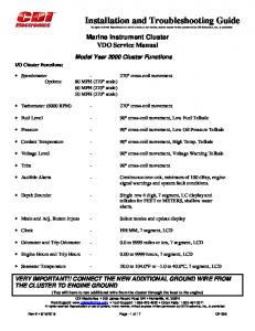
a cyclic manner. More accurate results are obtained with the turntable paused at each specified angle for a period at least as long as the siren cycle or the instrument averaging time, whichever is longer. As a siren loudspeaker heats, its electrical impedance (typically 11 O) increases. This causes the SPL produced by the siren loudspeaker to decrease with time. This decrease is largest at the start of continuous operation as the device heats rapidly. Eventually, the temperature of the siren loudspeaker approaches its maximum, and the decrease slows. Measurements of the SPL produced by siren loudspeakers taken after several minutes of continuous operation are more stable and provide a better indication of performance with prolonged use. The GSA K-Specification and CCR Title 13 require that a siren loudspeaker be on for 1 min prior to the start of acoustical testing. This period is shorter than the typical warm-up time during which many siren loudspeakers exhibit their most rapid decrease in SPL output. Acoustical performance tests required by SAE J1849 are started immediately after the siren is turned on and conducted for 1 min at each test point. A 10 min warmup period is being considered for the next revision of SAE J1849. Wail and yelp sounds are produced by increases and decreases in the frequency of a square wave. Any particular wail or yelp sound is characterized by its cycle rate and fundamental frequency range. For a square wave, harmonics are present at frequencies higher than the frequency of the square wave itself, which is the fundamental frequency of the square wave. Examples of how the square wave frequency varies with time for wail and yelp are shown in figure 1.
12
Figure 1. Examples of wail and yelp with cycle rates of 20 cycles per minute (cpm) and 240 cpm, respectively
13
Tables 5 and 6 summarize the frequency and cycle rate requirements of the GSA K-Specification, CCR Title 13, and SAE J1849 for the wail and yelp sounds.
Table 5. Frequency and cycle rate requirements for wail Parameter
CCR Title 13
SAE J1849
GSA K-Specification
Cycle rate lower limit in cycles per minute (cpm)
10
10
10
Cycle rate upper limit (cpm)
30
30
18
Minimum range of fundamental frequency
none
850 Hz
one octave*
Minimum fundamental frequency (Hz)
100
650
500
Maximum fundamental frequency (Hz)
2500
2000
2000
1000 or 2000
none
1000 or 2000
Octave band in which maximum sound pressure level is measured (Hz)
*Maximum fundamental frequency is equal to twice the minimum fundamental frequency.
14
Table 6. Frequency and cycle rate requirements for yelp Parameter
CCR Title 13
SAE J1849
GSA K-Specification
Cycle rate lower limit in cycles per minute (cpm)
150
150
150
Cycle rate upper limit (cpm)
250
250
250
Minimum range of fundamental frequency
none
850 Hz
one octave*
Minimum fundamental frequency (Hz)
100
650
500
Maximum fundamental frequency (Hz)
2500
2000
2000
1000 or 2000
none
1000 or 2000
Octave band in which maximum sound pressure level is measured (Hz)
*Maximum fundamental frequency is equal to twice the minimum fundamental frequency. The GSA K-Specification, CCR Title 13, and SAE J1849 require the measurement of the Aweighted SPL produced by a siren system 3 m away from the siren loudspeaker, or multiple siren loudspeaker system, on the device axis. Power supply voltages are specified according to the nominal voltage of the vehicle electrical system. Given this distance and the relatively large spacings commonly used between loudspeakers for ambulances that meet GSA K-Specification requirements, the measurements done for that document are usually not made in the far field of the dual loudspeaker systems tested. In both CCR Title 13 and SAE J1849, minimum requirements are stated for the A-weighted SPL measured 3 m distant from the source at every 10E increment in angle from !50E to +50E relative to the device axis in the horizontal plane. The test procedures of CCR Title 13 require that SPL measurement data be obtained by continuously rotating the loudspeaker at a uniform (but undefined) angular velocity on a turntable. In contrast, SAE J1849 requires that these tests be performed with the loudspeaker stationary, so that no ambiguity arises from measuring a time dependent signal produced by a siren loudspeaker that is constantly changing orientation during the measurement. Two classes of siren systems, A and B, are established by CCR Title 13 based on the A-weighted SPL measured at each angle for the lowest performing siren sound. At each angle, the SPL requirement for Class A sirens is 5 dB
15
higher than for Class B sirens. All of the A-weighted SPL requirements for the GSA KSpecification, CCR Title 13 Class A sirens, and SAE J1849 are given in tables 7 and 8.
Table 7. Minimum requirements for the maximum A-weighted sound pressure level (in dB re 20 µPa) produced by a siren system under test during any portion of its cycle Angle (degrees)
CCR Title 13 Class A*
SAE J1849**
GSA KSpecification†
0
120
118
123(wail), 122 (yelp)
±10
119
117
no requirement
±20
118
116
no requirement
±30
117
115
no requirement
±40
115
113
no requirement
±50
113
111
no requirement
*Measured with the “fast” averaging time setting (.125 s); a deviation of 1 dB below the specified value is allowed at any three of the eleven test points. **Measured with a .02 s averaging time; a deviation of 1 dB below the specified value is allowed at any three of the eleven test points if an additional total of 3 dB are measured at all of the remaining points. † Measured with the “fast” averaging time setting; a dual loudspeaker system is required. Note: All documents require that the power supply voltage be 13.6 V for devices intended to operate on nominal 12 V electrical systems.
16
Table 8. Minimum requirements for the minimum A-weighted sound pressure level (in dB re 20 µPa) produced by a siren system under test during any portion of its cycle Angle (degrees)
CCR Title 13 Class A* (wail only)
SAE J1849**
GSA KSpecification†
0
110
111
116
±10
109
110
no requirement
±20
108
109
no requirement
±30
107
108
no requirement
±40
105
107
no requirement
±50
103
106
no requirement
*Measured with the “fast” averaging time setting (.125 s); a deviation of 1 dB below the specified value is allowed at any three of the eleven test points. **Measured with a .02 s averaging time; a deviation of 1 dB below the specified value is allowed at any three of the eleven test points if an additional total of 3 dB are measured at all of the remaining points. † Measured with the “fast” averaging time setting; a dual loudspeaker system is required. Note: All documents require that the power supply voltage be 13.6 V for devices intended to operate on nominal 12 V electrical systems.
17
APPENDIX A— OCCUPATIONAL HEARING LOSS AND EXPOSURE TO SIREN NOISE Occupational exposure to noise can increase the risk of temporary or permanent hearing loss. Hearing loss often occurs cumulatively over time and can eventually affect the understanding of speech. In general, the extent of hearing damage incurred over time depends primarily on the noise SPLs and the duration of exposure. A great deal of information regarding noise in the workplace and its effects is provided by the National Institute for Occupational Safety and Health (NIOSH), a Federal agency that examines workplace hazards, in the Criteria for a Recommended Standard: Occupational Noise Exposure Revised Criteria 1998 [10]. Time-weighted average (TWA) noise SPL limits are given as a function of exposure duration. The higher the noise SPL, the shorter the duration of exposure allowed. Noise exposure should not equal or exceed an Aweighted TWA SPL of 85 dB for an 8 h workday. Exposure to a particular noise SPL for a given duration is considered by NIOSH to be equivalent to a SPL that is 3 dB higher for half that duration. Table 9 summarizes the A-weighted TWA noise SPL limits as a function of exposure duration recommended by NIOSH. These noise SPL limits are only meant to significantly minimize the excess risk due to occupational noise exposure of developing a maximum acceptable hearing impairment that still allows for speech discrimination. Exposure to noise SPLs in the workplace lower than the recommended limits does not entirely eliminate the risk of hearing loss resulting from occupational noise exposure or other factors such as aging, exposure to noise encountered outside of the workplace, and hazards such as ototoxic chemicals. Table 9. A-weighted time-weighted average (TWA) noise sound pressure level (SPL, in dB re 20 µPa) limits (not to be equaled or exceeded) recommended by NIOSH Duration of exposure per day (h)
TWA Noise SPL (dB)
8
85
4
88
2
91
1
94
1/2
97
1/4
100
1/8 (7 min and 30 s)
103
1/16 (3 min and 45 s)
106
1/32 (1 min and 53 s)
109
18
This NIOSH publication also includes information regarding hearing loss prevention programs and the use of personal hearing protection devices such as earplugs, earmuffs, and ear-canal caps. Hearing loss prevention programs are designed to quantify the nature and extent of hazardous noise exposure, monitor the effects of this exposure on hearing, and implement engineering or administrative controls to reduce noise exposure. Another publication available from NIOSH discusses hearing loss prevention programs in detail [11]. It contains names, addresses, and phone numbers of associations that can provide assistance in contacting professionals who can be hired to administer or participate in a hearing loss prevention program or perform noise measurements. Additional information concerning personal hearing protection devices is provided in The NIOSH Compendium of Hearing Protection Devices [12], which includes data for 241 different hearing protectors sold in the United States. Information required to obtain NIOSH publications is given in appendix C. Sirens produce noise that is loud enough to significantly increase the risk of temporary or permanent hearing loss. Reduction of noise SPLs in a vehicle cabin not only minimizes the risk of hearing damage, but also makes radio communication easier and improves driver performance [13]. A report concerning noise produced by sirens installed on fire trucks [14] recommended that siren loudspeakers be located in the front of the vehicle so that the vehicle itself isolates personnel from the noise. A similar study of sirens installed on ambulances [15] stated that driver noise exposure is minimized by locating the siren speakers in the front grille area. With the siren loudspeaker installed in the grille area, A-weighted SPLs in the driver cab were measured to be 16.3 dB to 22.0 dB lower than with the loudspeaker installed on the cab roof. This study also demonstrated that siren noise SPLs are attenuated in the ambulance driver cab a significant amount (7.1 dB to 12.8 dB measured with an A-weighting) by closed vehicle windows. During tests of sirens installed on vehicles, a lower maximum SPL can be achieved by performing these tests outdoors rather than inside a garage or other structure. Noise exposure during such tests can also be minimized by avoiding the area directly in front of the vehicle, where the SPL is highest, and wearing hearing protection.
19
APPENDIX B— REFERENCES [1]
Ambulance, Emergency Medical Care Surface Vehicle. Federal Specification for the Star-of-Life Ambulance KKK–A–1822D. U.S. General Services Administration, Washington, DC 20406; November 1994. Note: Proposed draft of “E” version is currently being coordinated with ambulance and related equipment manufacturers.
[2]
Sirens. Barclays California Code of Regulations, Title 13, Article 8. Barclays Law Publishers, South San Francisco, CA 94111.
[3]
Emergency Vehicle Sirens. SAE Recommended Practice SAE J1849. Society of Automotive Engineers, Warrendale, PA 15096–0001; August 1995.
[4]
Ross A. Little. Siren Standards. Department of California Highway Patrol, Sacramento, CA 94298–0001; July 1978.
[5]
Standard for Automotive Fire Apparatus. NFPA Standard 1901. National Fire Protection Association, Quincy, MA 02269–9101; 1996.
[6]
American National Standard Specification for Sound Level Meters. ANSI S1.4–1983 (R 1997). American Institute of Physics for the Acoustical Society of America, New York, NY 10005–3993; 1983.
[7]
American National Standard Design Response of Weighting Networks for Acoustical Measurements. ANSI S1.42–1986 (R 1998). American Institute of Physics for the Acoustical Society of America, New York, NY 10005–3993; 1986.
[8]
R. C. Potter, S. A. Fidell, M. M. Myles, and D. N. Keast. Effectiveness of Audible Warning Devices on Emergency Vehicles. Report No. DOT–TSC–OST–77–38. Work performed by Bolt, Beranek and Newman Inc., for the U.S. Department of Transportation, Washington, DC 20509; August 1977.
[9]
American National Standard Measurement of Sound Pressure Levels in Air. ANSI S1.13–1995 (ASA 118–1995). American Institute of Physics for the Acoustical Society of America, New York, NY 10005–3993; 1995.
[10]
Criteria for a Recommended Standard: Occupational Noise Exposure Revised Criteria 1998. DHHS (NIOSH) Publication No. 98–126. National Institute for Occupational Safety and Health, Cincinnati, OH 45226–1998; June 1998.
[11]
Preventing Occupational Hearing Loss - A Practical Guide. DHHS (NIOSH) Publication No. 96–110. National Institute for Occupational Safety and Health, Cincinnati, OH 45226–1998; October 1996. 20
[12]
The NIOSH Compendium of Hearing Protection Devices. DHHS (NIOSH) Publication No. 95–105. National Institute for Occupational Safety and Health, Cincinnati, OH 45226–1998; October 1994.
[13]
J. M. Finkelman, L. R. Zeitlin, J. A. Filippi, and M. A. Friend. "Noise and Driver Performance." Journal of Applied Psychology, Vol. 62, No. 6, pgs. 713–718, 1977.
[14]
R. A. Tubbs, and J. P. Flesch. Health Hazard Evaluation Report. HETA 81–059–1045, Newburgh Fire Department, Newburgh, New York. National Institute for Occupational Safety and Health, Cincinnati, OH 45226–1998; February 1982.
[15]
J. P. Flesch, and R. A. Tubbs. Health Hazard Evaluation Report. HETA 84–493–1583, General Services Administration, Washington, DC. National Institute for Occupational Safety and Health, Cincinnati, OH 45226–1998; April 1985.
21
APPENDIX C— INFORMATION REQUIRED TO CONTACT ORGANIZATIONS LISTED IN THIS GUIDE
Automotive Manufacturers Equipment Compliance Agency (AMECA) 1101 15th St., NW Suite 607 Washington, DC 20005 Phone: 202–898–0145 Department of California Highway Patrol (CHP) P.O. Box 942898 Sacramento, CA 94298–0001 Phone: 916–445–1865 General Services Administration (GSA) Federal Supply Service Bureau Specifications Section, Suite 81100 470 East L’Enfant Plaza, SW Washington, DC 20407 Phone: 202–619–8925 National Institute for Occupational Safety and Health (NIOSH) Information Resources Branch Robert A. Taft Laboratories 4676 Columbia Parkway Cincinnati, OH 45226–1998 Phone: 800–356–4674 (recorded message system) Alternate Phone: 513–533–8120 Society of Automotive Engineers (SAE) 400 Commonwealth Drive Warrendale, PA 15096–0001 Phone: 724–776–4970
22
SUPPLEMENT— CONTACT INFORMATION FOR COMPANIES THAT MANUFACTURE AND/OR SELL SIREN COMPONENTS The list in this supplement is provided solely for informational purposes. This supplement is not part of the Guide to Test Methods, Performance Requirements, and Installation Practices for Electronic Sirens Used on Law Enforcement Vehicles (NIJ GUIDE 500–00). No approval or endorsement by any government agency of any company or commercial product is intended or implied. Note: Manufacturers can provide names of local distributors if necessary. Able 2 Products PO Box 543 Cassville, MO 65625 Phone: 800–641–4098 Adamson Industries 314 S. Broadway Lawrence, MA 01843 Phone: 800–232–0162 Atlas/Soundolier 1859 Intertech Dr. Fenton, MO 63026 Phone: 800–876–7337 Carson Manufacturing Company 5451 N. Rural St. Indianapolis, IN 46220 Phone: 317–254–2665 Cast Products P.O. Box 1202 Highway 127 Athens, AL 35611 Phone: 800–468–2278 Code 3 10986 N. Warson Rd. St. Louis, MO 63114 Phone: 314–426–2700
S-1
Federal Signal 2645 Federal Signal Dr. University Park, IL 60466 Phone: 708–534–4745 Grothe Electronics 2206 N. 53rd St. Milwaukee, WI 53208 Phone: 414–442–5106 Lund Industries 303 Messner Dr. Wheeling, IL 60090 Phone: 800–504–1460 M&M Distributing 932 Coronado Parkway Denver, CO 80229 Phone: 303–288–8150 Motorola Aftermarket & Accessories Division 1313 E. Algonquin Rd. Schaumburg, IL 60196 Phone: 800–422–4210 Premier Hazard Systems 136 Gamma Dr. Pittsburgh, PA 15238 Phone: 412–963–8750 Pursuit Unlimited 1329 N. Harrison Shawnee, OK 74801 Phone: 405–275–7177 Sanming Sound 17921 Lyons Circle Huntington Beach, CA 92647 Phone: 714–842–9969
S-2
Signal Vehicle Products 1611 Gunn Highway Odessa, FL 33556 Phone: 800–875–8003 Southern Public Safety Equipment 5223-A W. Market St. Greensboro, NC 27409 Phone: 800–845–0045 Tomar Electronics 2100 W. Obispo Gilbert, AZ 85233 Phone: 800–338–3133 Unitrol 1108 Raymond Way Anaheim, CA 92801 Phone: 800–854–3375 Veto Enterprises 212 W. Exchange St. Sycamore, IL 60178 Phone: 815–895–9755 Phone: 800–523–4733 (outside Illinois) Whelen Engineering Route 145 Winthrop Rd. Chester, CT 06412 Phone: 860–526–9504 Winder Police Equipment 5313 S. Telegraph Rd. Dearborn Heights, MI 48125 Phone: 313–295–4900
S-3
U.S. Department of Justice Office of Justice Programs 810 Seventh Street N.W. Washington, DC 20531 Janet Reno Attorney General Daniel Marcus Acting Associate Attorney General Mary Lou Leary Acting Assistant Attorney General Julie E. Samuels Acting Director, National Institute of Justice Office of Justice Programs World Wide Web Site: http://www.ojp.usdoj.gov
National Institute of Justice World Wide Web Site: http://www.ojp.usdoj.gov/nij