Guiding Robots through Wireless Location Positioning Kevin Curran, Joan Condell, James Knox School of Computing and Intelligent Systems Faculty of Computing and Engineering, University of Ulster, Northern Ireland, UK Email:
[email protected] accurately cannot be underestimated. Industry has longed to be able to effectively track objects, components, assets and people. Ultra Wide Band technologies are often described as the next generation of real time location positioning systems. In the world today industry is becoming more competitive and any technology which can provide a competitive edge is welcomed and much sought after. However not all technologies live up to their claims which can prove very costly to industry.
Abstract - Indoor Positioning Systems (IPS) track objects in buildings. Examples of tagged objects are patients or equipment in a hospital whilst discovered objects could be people in burning buildings or soldiers on a battlefield. Ultra Wide Band (UWB) location determination aims at delivering high positional accuracy in harsh industrial environments that cause problems for traditional systems due to electromagnetic interference. UWB systems can calculate the location of tags which are designed to be mounted on assets or worn by a person. They transmit UWB signals that are received by sensors which contain an array of antenna and ultra-wideband radio receivers. The data from these sensors combined with dedicated software uses algorithms to work out the angle of arrival (AOA) of the UWB signal from the tag which is then compared to the time difference of arrival (TDOA). The robotics industry can benefit from advanced location detection systems. We examine here the use of ultra wide band technology in tracking items such as mobile robots.
A challenge in robotics is the integration of robots in everyday environments. This has been present in the Framework Programme of the European Community. Robots must become part of everyday life as assistants. Nevertheless there is still an important barrier between the latest developments on research robots and the commercial robotic applications available. Research groups working on robotics receive numerous requests to take the robots to social events. However, conducting these demonstrations in venues can be difficult, unless the robot runs the same programs under boundary conditions known a priori. A fast and easy deployment of robots in new areas is necessary to get robots operating outside research centres and beyond the continuous supervision of staff. Robots must be capable of being installed and put into operation within very short periods of time.
Keywords-robotic navigation, mobile positioning, location determination, wireless
I. INTRODUCTION There are various types of location systems some wireless, others based on Video imaging and digital location systems but they all have their advantages and disadvantages. Outdoor location systems are costly to implement. The infrastructure required for these types of systems include satellites and receivers. Their performance can be affected by weather conditions and other atmospheric conditions and the accuracy which they deliver is not as accurate as that of indoor location systems. Indoor location devices still have some problems such as the ability to locate objects exactly. This can be caused by a number of factors depending on the system being used. Each system has its advantages and its disadvantages. Some can provide a high degree of accuracy but are not suitable for manufacturing applications as they do not perform well in these conditions due in part to interference caused by other machinery. The cost of some of these systems is also a factor as they can be very expensive to implement. Scalability is another issue that requires investigation. However in order to evaluate these systems we must look at how the different systems operate. The benefits of being able to track objects
978-1-4673-0856-4/12/$31.00 ©2012 IEEE
This research investigates the use of a real time indoor positioning system to guide robots in performing various tasks. The aim is to evaluate and test the accuracy, precision and robustness of a location detection system in a small geographical area in order to ascertain how beneficial an indoor UWB location detection system could be in the field of robotics and how industry could benefit from this technology [1]. The adoption of radio frequency is simpler than facerecognition using vision, guarantees a higher success rate and allows the identification of each robot regardless of its morphology. There might be similar robots of the same shape or colour. As wireless networks have become omnipresent, we plan to examine positioning solutions that would allow robots to locate themselves by listening for radio beacons such as 802.11 access points.
25
802.11 interface which combine to predict location positions. It uses known positions that are stored in a database combined with 802.11 signals to establish a user’s location. However when tested to find a users position in a relatively small geographical area like a University Campus, it does not achieve very good accuracy.
II. LOCATION POSITIONING Indoor location systems are required to provide more accurate location detection than outdoor systems and they often have to work in harsher environments. Often RF signals are interfered with because of electromagnetic discharge from other sources. Therefore indoor location systems still have problems to overcome regarding the accuracy location detection. Infrared and ultrasound are useful in environments where wireless radio frequencies may interfere with critical equipment. Ultrawideband employs sonic detection methods that help overcome many of the difficulties that other indoor location systems suffer from. Ultra-wideband location detection systems combine sensors and transmitting tags to provide coverage of an area referred to as intelligent space which is where accurate information can be obtained about location of objects. The robotics industry can also benefit from advanced location detection systems. Using a combination of sensors and taking accurate measurements of a tagged robots location, one can accurately predict, with better accuracy, the position of a robot in relation to its surroundings. Mobile robots will then be able to operate autonomously in their environment, with accurate prediction of location paths and navigation direction, making them more productive and reliable.
B. Camera Based Indoor Positioning Vicon is a digital optical and video based motion tracking system that allows for a better understanding of movement. By being able to track and analyse movement it offers solutions to real life problems. This system is designed to be expandable and allow easy integration into the working environment. The system allows for the accurate tracking of objects by use of cameras, triangulation and software that allows users to analyse the data. A benefit of this system is that it does not use radio frequency (RF) which is sometimes prone to metallic interference. It claims to be able to provide a positional accuracy of better than 1 mm. However the Vicon system is very expensive and involves the installation of many cameras. C. Ultra-Wideband Ubisense Ultra-wideband (UWB) is a radio technology that can be used at very low energy levels for short-range highbandwidth communications using a large portion of the radio spectrum. Ultra wideband has gained in popularity as a new technology and has been the focus of much research and development. It offers solutions to applications, such as seethrough-the-wall, security applications, family communications and supervision of children, search and rescue, medical imaging, control of home appliances, which make UWB an ideal candidate for wireless home network [3]. It is essential to investigate and identify real world needs where location awareness technology can make a difference. Ubisense provides a breakthrough in the field of accurate 3D positioning. It utilises ultra-wideband in the field of Radio Frequency (RF) to deliver accurate 3D positioning which is scalable and offers real time performance. This can be used over a large geographical area, especially for in-building locations.
A. Wi-Fi (802.11) Based Indoor Positioning Sound navigation and ranging is a technique that uses sound propagation (usually underwater) to navigate, communicate with or detect other vessels. Sonar may be used as a means of acoustic location. Acoustic location in air was used before the introduction of radar. Radio Detection and Ranging, early systems were used to detect metallic ships in dense fog but not its distance. During the Second World War Britain exploited this technology as a defense system against German aircraft attack to great effect. Radar was able to identify the range, altitude direction, or speed of both moving and fixed objects such as aircraft, ships, motor vehicles, weather formations, and terrain. The Radar system works by using a transmitter to emit radio waves that are reflected back by the object that one is trying to locate. Wi-Fi positioning algorithms can analyse signal strength. One commercial implementation is from Ekahau. The Ekahau RTLS system uses software based location tracking to accurately track assets and people over any existing Wi-Fi network. It does this by using algorithms to compute the location of tags which have the Ekahau location protocol built in and use 2- way Wi-Fi signals to deliver the required accuracy across a geographical area, without the need to install any software or hardware in remote sites.
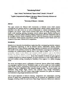
Fig 1: Ubisense compact tags, single sensors and series 7000 sensors
The PlaceLab architecture is an example of an indoor positioning system. It is made up of three elements: radio beacons in the environment; databases holding beacon location information and PlaceLab clients that estimate the location from these data [2]. PlaceLab uses open source software and an
Ubisense is targeting its sensing and middleware technologies at a number of markets, including healthcare, security, workplace productivity and military training [4]. The
26
development and deployment tools make the system easy to design, implement and maintain. Proprietary tags communicate with the series 7000 sensors (see Fig 1). Ultra– wideband is a technology based on radio frequency which has been used by to build real time systems that can provide a high degree of positional accuracy, in real time to within 15cm. It can work in very harsh and challenging environments where conventional RFID and Wi-Fi have experienced problems with interference.
from a continuous geometric description to a decomposition– based geometric map or even a topological map. The first step of path planning system is to transform this possible continuous environmental model into a discrete map suitable for the chosen path–planning algorithm.
III. ROBOTICS AND LOCATION DETERMINATION Different sensors are used to extract meaningful information and measurements that can help provide information about the robots environment [5]. For an autonomous mobile robot to operate successfully it requires three things: perception of its environment, decision making capabilities and a way to execute information received in a meaningful manner (for example path planning and navigation to execute a goal i.e. moving from one position to another efficiently, safely and successfully avoiding objects). This requires problem solving skills and strategic planning together with navigational capabilities. Many different types of systems are currently on offer for outdoor and indoor location detection systems. Exteroceptive sensors are used to obtain information from the external environment.
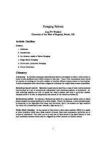
Fig 2: Beacon aided navigation for Robots
Location information can also be derived from analysis of data such as video images, as in the MITSmart Rooms project [7]. Accurate object locations can be determined in this way using relatively cheap hardware, but large amounts of computer processing are required. Furthermore, current image analysis techniques can only deal with simple scenes in which extensive features are tracked, making them unsuitable for locating many objects in cluttered indoor environments.
Robots can obtain information from their environment using cameras that allow the robot to distinguish shapes and recognise objects. Proprioceptive Sensors measure the robots internal workings, for example the battery voltage level or it can measure the rotation of the robots wheels to measure distance travelled. The advantages of mobility cannot be fully exploited without the capability of navigating [6]. Sensors can provide lots of data that can be processed to provide meaningful information. However without being able to accurately predict the robots exact location at a given time then this data received would be unreliable and lead to errors. The goal for any location system is to be able to provide accurate positioning information within a coordinate system. This will allow a robot to move autonomously (see figure 2). Ultra wideband claims to be able to accurately locate a transmitting RF tag to within 6cm in intelligent space. This paper investigates the accuracy of these claims and how this technology could be combined with the field of robotics’ to accurately determine in real time a robots location in relation to its environment. A robots environment can include many different geometric obstacles and terrain conditions. In order to make accurate decisions not only does a robot require sensors to detect obstacles for path planning but it also needs to know its exact location, in order to benefit from the data it receives. Using Ultra wideband we explore how this location accuracy can be achieved and how it can be applied to the field of robotics. The Robots environment representation can range
IV. LOCATION DETERMINATION PROTOTYPE DEVELOPMENT The aim here is to develop and test the accuracy of ultra wideband location detection systems and its ability to track in realtime movement over a small geographical area of a robot. The system uses battery powered radio tags and a cellular locating system to detect the location of the tags.
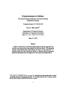
Fig 3: State diagram for the Location Detection System
27
difference of arrival (TDOA) of a signal transmitted from the tag to the four receivers mounted at each corner of the room. Locating a Tag by measuring the TDOA of a signal transmitted from the tag and received by the synchronized sensors allows for the accurate location of the tag to be identified accurately in real time. A plan was created for the area covered by the sensors and the identification numbers of each sensor. Master sensor ID 00:11:CE:OF:56 controls the timing for the other sensors which are connected to it. The sensors are calibrated to a central fuducial point on the floor; this reference point is used to verify that the system is correctly set up. Addresses from each sensor are relayed via the master sensor to the location platform software which is installed on the laptop. The software then constructs a grid diagram showing the location of the sensors in relation to the space which they monitor. Each sensor had to be individually calibrated to ensure that background noise was eliminated. The calibration process allowed the thresholds to be set for each sensor in order to reduce interference. Figure 5 shows results of running the software after calibration to ensure that the timing signals from the sensors were operating correctly and that the area to be covered could be scanned. This was performed before introducing the Tags in order to reduce interference.
The hardware used was Ubisense. The cellular locating system emits precisely timed short bursts of RF energy to provide accurate triangulation of the position of the transmitting tag. Fig 3 shows a representation of the processes involved in a RF tag being located and tracked. When the software for the system initially loads the user is presented with the Platform Control which informs the user that connection to the Ubisense Core server has been initialized and is up and running. The Sensor properties interface gives the user information relating to the location of the sensor about the X, Y and Z axis. The Yaw is the directional degrees at which the Sensor is tilted towards the Fuducial Calibration Point (see Fig 4).
Fig 4: Properties of the master sensor location.
Users will utilize battery powered radio tags to be mounted on a robot or worn by a person. These tags when activated will transmit RF energy to provide accurate data that allows the location of the tag to be identified through the use of triangulation. The Location engine includes software required for the sensors to track battery powered tags, in real time. The system was mounted at a recommended height of 3 meters above the floor level. The sensors were attached to the wall using brackets and were then maneuvered to point to a central location in the middle of the floor at approximately 45 degree angle ensuring a good line of sight. All four sensors were connected to an Ethernet switch using cat 5 network cables and one of the sensors was configured to be the Master and the other sensors slaves. A timing cable was connected from each slave to a cable port on the master sensor. The cables were connected via a switch to a laptop. Identification of the sensors was achieved and their location established on a grid matrix. This allowed calibration of the sensors in relation to the space which they monitored.
Fig 5: Sensors scanning area to be covered
As can be seen from Fig 6, each sensor is scanning the area plan searching for a Transmitting tag. The master sensor coordinates the timing signals of the scans to ensure synchronisation accuracy. When a radio tag is introduced it will transmit a signal back to the sensors located at each corner of the room. Algorithms are used to work out the difference between the timing signals and the radio transmitted signal from the tags which are picked up by the sensors. In this way the system accurately works out the location of the Tags to a degree of accuracy claimed to be within 6 cm. Factors that may affect the accuracy of the readings could be the temperature of the room or the humidity of the room. Other factors may be reflection from objects
Tags are located by accurately computing the time
28
within the room or attenuation loss from the tags. Testing of the systems performance under various conditions will allow the location accuracy claims made by the manufacturers to be examined. Movement of the tags at various speeds will be tested to see how fast the location data can be retrieved by the system and the accuracy of that data. Tests involved running the system in real-time, with tag number 010-000-015-099 located at the centre of the area plan. The location of the Tag is indicated by the red dot at the junction of the blue waves.
The drawbacks of using this method are that the scanning signals from the sensors do not always intersect at one point. Environmental factors can influence the readings through reflections of signals from surfaces. Humidity may also cause interference. Estimations of transmitting tag locations from the results supplied by the sensors compared with the real location of the tags position in relation to a measured grid map of the area covered by the sensors indicate some discrepancies. This is especially the case the further the transmitting tags are moved away from the centre of the area being scanned. There were areas beneath the sensors that are dead zones where signals from the sensors do not register.
V. EVALUATION We evaluated how different materials may influence the accuracy of the transmitting tags location and how accurately the location system can track the movement and location of a tag moving from point A to point B in a room. The floor was mapped out in a one meter square grid. The Centre of the actual floor corresponds to Grid reference 1.5 on the Y axis and 2.5 on the X axis on. A number of readings were taken around the area covered by the sensors. This was done methodically starting at grid reference (0, 0 Y, axis - 0, 0 X, axis). Further readings were taken moving the tag to different locations where the grid lines meet finishing at grid ref reference (0,3Y, axis 0, 5 X, axis). This ensured that all cross references were covered. Fig 7 shows the results of a tag id 101-111-015-099 being paced at grid reference .25cm on the Y axis and .25 cm on the X axis. The results are then recorded and compared with the position where the sensors indicate that the tag is. The yellow line indicates where the sensors have located the tag on the Y axis and the green line indicates where the sensors have located the tag on the X axis. The chart shows that the level of error is greater along the Y axis than along the X axis. We experimented to see how a liquid, in this case water, can effect and influence the location accuracy readings. Results indicate that water does cause interference with the location accuracy reading of the ultra wideband location detection system - a positional change is recorded. These results above raise the question - if a person is wearing a transmitting tag how will their body (which contains 70% fluid) interfere with the accuracy readings. We examined how different materials can effect and influence the operational accuracy readings. Lead and tin do cause interference to the accurate location of transmitting tag. Materials made from plastic or wood do not interfere with the capabilities of the ultra wideband location detection system. The four sensors were able to accurately pinpoint the location of the tag.
Fig 6: Tag moved 1/2 meter back from centre towards the master sensor
Blue wave signals become more intense and concentrated as the tag moves away from the timing sensors 00:11: CE: 00: OE: 71 and 00:11: CE: 00: OF: 38. Location testing is crucial so that estimated results can be compared with the physical location of the transmitting tag. The floor area is accurately marked out to scale to allow accurate comparison of results on screen to the actual location of the tags position. The sensors locate the tags in 3D space from a particular point in space. The basic directions in which one can move are up/down, left/right and forward/backward. Movement in other directions can be expressed in terms of just these three definitions. Errors can result from environmental factors such as false readings from reflective surfaces. In order to compensate for these environmental displacement errors it is important to calibrate the sensor thresholds. To do this it is important to set the “Disabled Radio” tag on the master of the cell and then calibrates the four sensors. This compensates for errors in the real environment, the perpendicular distance and the angle between the sensors. The sensors measure distances with different sensitivities as the distance and the angle of transmitted tag signals varies. We can measure the distance error. Distance in this case is defined as the measurement from the wall mounted sensors to the transmitting tag. The error rate and time calculations using the position of the transmitting tag have shown that depending on the location of the tag the accuracy of the results can be influenced when deciding the exact location of the tag. Trilateration is employed by the wall mounted sensors to locate the position of the transmitting tag.
29
Distance in meters X axis 0.25
0.5
0.75
1
1.25
1.5
1.75
2
2.25
2.5
2.75
3
3
Distance in meters Y axis
2.75 2.5 2.25 2 1.75 1.5 1.25 1 0.75 0.5
Fig 9: Position of the transmitting tag as it is moved further away
0.25 0
Fig 7: Location results for Tag id 101-111-015-999
VI. CONCLUSION
Fig 8: The influence of liquid on tag transmit performance
We showed that it is possible to setup a location detection system that is capable of locating transmitting tags within a small geographical area. However the accuracy of the transmitting tags location detection can be influenced by many factors including reflection from other surfaces and atmospheric conditions. When multiple transmitting tags were introduced into the area covered by the sensors, the systems performance became more unreliable which would influence the reliability and suitability of this system in the robotics field. Using a combination of sensors and taking accurate measurements of a tagged robots location, one can accurately predict, with better accuracy, the position of a robot in relation to its surroundings. Robots will be able to operate autonomously with accurate prediction of location and direction, making them more productive and reliable.
Fig 8 shows the position of the transmitting tag as it is moved further away from the centre of the room. The reliability of the location detection system is affected by how far the transmitting tags are from the central position covered by the sensors. Fig 9 shows how the error rate becomes more acute the further the tag is moved from the central position in the room. This research was concerned with the testing of an accuracy of an indoor location system utilising ultra wideband. The key to robot navigation is self localisation; this allows a robot to navigate between two points. By using a combination of map building and self localisation a robot will be able to successfully plan paths in relation to its surroundings in the real world. Determining the location of objects or people in a smart space is one of the prerequisites enabling smart applications. An Ultra wideband location detection system has the advantages of being able to carry out precision localisation and handle multi-path signals. Sensor network-based ultra wideband location detection system provides greater accuracy than other systems.
REFERENCES
30
[1]
Bekey, G. (2005) Autonomous Robots: From Biological Inspiration to Implementation and Control. Cambridge, Mass.: Mit Press
[2]
Curran, K. Furey, E. (2008) “Pinpointing users with location estimation techniques and wifi hotspot technology”. Int. J. Network Mgmt, Wiley
[3]
Rashid, A. Khatun, S. (2006) “Performance of Ultra-Wideband Time-ofArrival Estimation Enhanced with Synchronization Scheme”. ECTI Transactions on Electrical Eng, Electronics and Communications, Vol 4, No. 1.
[4]
Steggles, P. Batty, P. Sails, T (2003) “Local positioning system: New possibilities for urban combat training”. White paper, IITSEC 2003.
[5]
Ohba, R (1992) Intelligent Sensor Technology. John Wiley
[6]
Nehmzow, U, (2006) Scientific Methods in Mobile Robotics. SpringerVerlag
[7]
Pentland, A. (1995) “Machine Understanding of Human Action”. Proceedings of 7th International Forum on Frontier Telecommunication Technology, Tokyo, Japan.