Available online at www.sciencedirect.com
ScienceDirect Procedia Technology 25 (2016) 775 – 784
Global Colloquium in Recent Advancement and Effectual Researches in Engineering, Science and Technology (RAEREST 2016)
H-Infinity Loop-Shaping Controller for Load Frequency Control of a Deregulated Power System Arlene Davidson Ra*, Dr. S. Ushakumarib a
Research Scholar, Dept. of Electrical Engineering, College of Engineering Trivandrum, India b Professor, Dept. of Electrical Engineering, College of Engineering Trivandrum, India
Abstract Load frequency control is an essential component of Automatic Generation Control of power systems. Deregulated power system isa highly complex and uncertain system because of multiple bilateral transactions taking place. This necessitates the use of advanced robust controllers for load frequency control. A decentralized load frequency controller using H-infinity based loopshaping method is suggested for a two area deregulated non-reheat thermal power system in this paper. The connections between each control area with the rest of the system as well as the contracts existing in a deregulated system are treated as input disturbance signals to achieve decentralization. Dynamic responses for three contract cases of operation in a deregulated system using the H-infinity controller are obtained. © 2016 2015The TheAuthors. Authors.Published Elsevier Ltd. © Published byby Elsevier Ltd. This is an open access article under the CC BY-NC-ND license (http://creativecommons.org/licenses/by-nc-nd/4.0/). Peer-review under responsibility of the organizing committee of RAEREST 2016. Peer-review under responsibility of the organizing committee of RAEREST 2016 Keywords:Deregulation, load frequency control, H-infinity control, loop-shaping, unilateral, bilateral, contract violation
1. Introduction Automatic Generation Control (AGC) is one of the significant problems in electric power system design and operation. Any deviation in frequency with sudden load perturbation can directly influence power system operation and system reliability. A non-nominal frequency results in a lower quality of the delivered electrical energy. Too low frequencies lead to vibrations damaging steam turbines which in the worst case may have to be disconnected. A large frequency deviation can cause an unstable condition for a power system. The main objectives of load frequency control (LFC) in an interconnected power system include maintaining system frequency at nominal value and minimizing unscheduled tie-line power flows between neighbouring control areas[1]. Electric power industry is currently undergoing transition from a vertically integrated structure to a horizontally integrated structure with the main objectives of bringing down the price of electrical energy, improving the service standards and developing a competitive market environment. In this new framework, generation, transmission and distribution are handled by separate entities termed as Generation Companies (GENCOs), Transmission Companies (TRANSCOs) and Distribution Companies (DISCOs). Since there are several GENCOs and DISCOs in the deregulated structure, any DISCO has the freedom to make a contract with any GENCO in any control area for purchase of power.All such transactions have to be cleared through an impartial entity called an Independent System *Corresponding author Tel : +91-9400818313; Email id :
[email protected]
2212-0173 © 2016 The Authors. Published by Elsevier Ltd. This is an open access article under the CC BY-NC-ND license (http://creativecommons.org/licenses/by-nc-nd/4.0/). Peer-review under responsibility of the organizing committee of RAEREST 2016 doi:10.1016/j.protcy.2016.08.172
776
R. Arlene Davidson and S. Ushakumari / Procedia Technology 25 (2016) 775 – 784
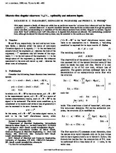
Operator (ISO). The ISO has to control a number of ancillary services, one of which is AGC. Several methods have been proposed to design load frequency controllers for deregulated power systems. The operational structures resulting from deregulation are highlightedin [2]. A ramp following controller is designed for a deregulatedsystemin [3]. Donde et al. [4] have taken into account the effect of bilateral contracts in modelling the system and simulation are done considering bilateral contracts and contract violation. In [5], LFC synthesis problem is formulated as a mixed H2/H∞ static output feedback control problem to obtain a desired PI controller. A decentralized Neural Network controller for LFC in a deregulated power system is proposed in [6]. Genetic algorithm is used for optimization of integral gains and bias factors in AGC for a three area power system after deregulation in [7]. Genetic algorithm optimization techniques are employed for tuning PID controller gains in [8] for a four area deregulated power system. Optimal output feedback control and reduced order observer are made use of in [9] for a simplified model of the deregulated system.Two degree of freedom internal model control ( IMC ) method is used to tune decentralized PID type load frequency controllers in [10]for a deregulated environment.A load following controller in deregulated scenario has been designed in [11]. Structured singular value method is used for robustness analysis in [12]. Fractional Order PID controller is applied to AGC of multi area thermal system with reheat turbines under deregulated environment in [13].Optimal output feedbackcontroller is used in [14] for LFC in deregulated environment for multi-source combination of hydro, reheat thermal and gas generating units in each control area.Optimal load frequency controller for a two area non-reheat thermal deregulated power system using genetic algorithm is given in [15]. Being a highly complex and uncertain system because of the multiple bilateral transactions taking place, a fixed controller will not be able to take care of the uncertainties in the system and so robust controller design is essential for LFC in the restructured power scenario. Literature review suggests that only a very few works have been done on application of robust controllers for load frequency control on deregulated power systems. It is also seen that Hinfinity controller based on loop-shaping has not yet been attempted in deregulated power systems. This paper deals with the design of H-infinity loop-shaping controller for two-area deregulated non-reheat thermal power system. Section 2 details the modelling of the deregulated power system. Section 3concerns the design and application of H-infinity controller design based on loop-shapingfor the same system.Section 4.1 and Section 4.2 give the controller design for Area 1 and Area 2 respectively. The dynamic response of the two area deregulated power system with the application of the mentioned controller is given in Section 4.3. Section 5 gives the summary of the work presented. 2. LFC In A Deregulated Power System The LFC in a deregulated power market should be designed to accommodate all possible transactions such as Poolco-based transactions, bilateral transactions and a combination of these two transactions. In bilateral transaction, any DISCO has the freedom to have a contract with any GENCO in its own and other control areas whereas in Poolco-based transactions, GENCOs participate in LFC of their own control areas only. In a competitive electricity market, Poolco and bilateral transactions can take place simultaneously. The schematic block diagram of a two-area deregulated power system consisting of two GENCOs and two DISCOs in each area is given in Fig. 1. In order to meet the Poolco-based and bilateral transactions, a DISCO Participation Matrix ( DPM ) is used. The number of rows of DPM is equal to the number of GENCOs and the number of columns equal to the number of DISCOs. Each entry of DPM is defined as contract participation factor. Thus ‘cpfkl’ is contract participation factor between kthGENCO and lthDISCO and indicates the fraction of the total load power contracted by DISCO ‘l’ fromGENCO‘k'. For a two area system with two GENCOs(GENCO1, GENCO2 ) and two DISCOs( DISCO1, DISCO2 ) in area 1 and two GENCOs ( GENCO 3, GENCO 4 ) and two DISCOs ( DISCO3,DISCO 4)in area 2, DPM is given by (1)
777
R. Arlene Davidson and S. Ushakumari / Procedia Technology 25 (2016) 775 – 784
Fig.1. Schematic block diagram of a two area deregulated power system
The sum of all entries in a column of DPM is unity. ie., ∑
= 1; for l = 1,2,.....Nd
(2)
where ‘Ng’ is the total number of GENCOs and‘Nd’is the total number of DISCOs. The generation of each GENCO must track the contracted demands of DISCOs in steady state. The expression for contracted power of kth GENCO with DISCOs is given by ∆ , ; fork = 1,2,.....Ng (3) ∆ , = ∑ Where∆Pgc,k is the contracted power of kthGENCO and ∆ , is the total load demand of lthDISCO. Thescheduled steady state power flow on the tie-line is expressed as the difference of total power exported from GENCOs in control area 1 to DISCOs in controlarea 2 and total power imported by DISCOs in control area 1 from GENCOs in control area 2. ∆
,
= ∑
∑
∆
− ∑
,
∑
∆
,
(4)
The tie-line power error is defined as ∆
,
=∆
,
− ∆
,
(5)
vanishes as the actual tie-line power flow reaches the scheduled At steady state, tie-line power error, ∆ , power flow. This error signal is used to generate the respective Area Control Error ( ACE ) signal as in the conventional power system.
778
R. Arlene Davidson and S. Ushakumari / Procedia Technology 25 (2016) 775 – 784
=
∆
+ ∆
=
∆
+
= −
where
(6)
,
∆
where Pr1, Pr2 are the rated area capacities of area 1 and area 2 respectively.
The total load of the kth control area ∆ of the DISCOs of the kth control area. ∆
=∑
,
(7)
,
∆
,
+ ∆
,
is expressed as the sum of the contracted and uncontracted load demand
(8)
,
where ∆ , is the contracted load demand of the kthDISCO and ∆ DISCOs in ktharea.
,
represents the uncontracted load demands of
3. Design of H-Infinity Loop-Shaping Controller The objectives of H-infinity controller synthesis include ensuring the stability of systems in the face of uncertainties in the system referred to as robust stability. In the control design for uncertain systems, it is necessary to know the level of performance once stability is ensured. This is called as robust performance. The term ‘loop-shaping’ refers to adjustment of frequency response of whole system within certain bounds so as to ensure sufficient robust performance and robust stability [16]. Consider Gi(s) as a linear time invariant model for a given control area i with the following state space model: ̇
= =
+ +
+
(9.1) (9.2)
where the suffix ‘i’ is used to represent the variable for a particular control area, is the plant coefficient matrix, is the disturbance matrix, is the control matrix, is the output matrix, is the feedforward matrix, Xi is the state variable vector, wi is the disturbance vector, uiis the control vector and yi is the measured output vector. The H-infinitycontroller for the linear time invariant system Gi(s) with the state space realization given in (9.1-9.2) is to find a matrix K, given by u = Kyi, such that the resulting closed loop system is internally stable and the H-infinity norm from w to z is smaller than γ, a specified positive number, ie., ‖
‖∞ ˂ γ
(10)
For a given plant G and controller K, the closed-loop performance objectives are given by ) termed ‘Sensitivity, S’ which is the gain from output disturbance to controller input, or the gain . ( + from reference signal to tracking error. ) ) which is the transfer function from input disturbance to plant output. The reciprocal of this B. (( + term indicates the maximum permissible additive controller perturbation for closed-loop stability. ) ) which is the transfer function from output disturbance to controller output. The reciprocal of . ( ( + this term represents the maximum allowable additive plant perturbation for closed-loop stability. ) ) termed ‘Complementary Sensitivity, T’ which is the transfer function from controller input D. ( ( + disturbance to plant output and also the same as transfer function from control input to output. The reciprocal of this term represents the maximum permissible multiplicative plant perturbation for closed-loop stability. A. and B.are robust performance objectives and are required to be small at low frequency while C. and D. are robust stability objectives which are required to be small at high frequency [19]. According to the mentioned properties, in Hinfinity loop-shaping method, open loop singular value shaping is done.
R. Arlene Davidson and S. Ushakumari / Procedia Technology 25 (2016) 775 – 784
The different steps in the computation of the controller are listed below : Choose a desired loop-shape whose transfer function is given by Gd whose performance bound and robustness bound are as in Fig.2. 2. Conversion of Gdtothe form in which the singular values of the nominal plant are shaped to give the desired open-loop shape, Gd. The shaped plant can be expressed as Gs=GW, where W is a prefilter and G is the nominal plant transfer function, so that the singular values ofGdapproximates the singular values of Gs . Methodsfor computing W for loop-shaping within a required frequency rangeis given in [17] and [18]. 3. Computation of optimal loop-shaping controller by using Glover-McFarlane [19] normalized coprime factor stabilization method whereby the optimal controller has the property that the singular value plot of the shaped loop Ls=G*W*Ks, where Ks is the controller, matches the target loop shape Gd optimally, roughly to within plus or minus 20*log(γ) db. The value of γ is an indicator of the accuracy to which the optimal loopshape matches the desired loop shape and acts as an upper bound for the resonant peak magnitude of the closed loop transfer function. ‘γ’ gives a good indication of robustness of stability to a wide class of unstructured plant variations, with values in the range 1< γ> 1. Also, if minimum singular value of open-loop gain with controlleris