Dec 19, 2008 - The halo generator code package HTGEN includes generic interface routines to ... simulation code for the scattering off thermal photons is described in [12]. ..... ment; available from http://www.linearcollider.org/wiki/doku.php.
EUROTeV-Report-2008-076
HALO AND TAIL GENERATION COMPUTER MODEL AND STUDIES FOR LINEAR COLLIDERS H. Burkhardt, I. Ahmed, M. Fitterer, A. Latina, L. Neukermans, D. Schulte December 19, 2008
Abstract Halo particles in linear colliders can result in significant losses and serious background which may reduce the overall performance. We discuss halo sources and describe analytical estimates. We developed simulation codes for the dominant halo production processes and provide interfaces for tracking programs. Estimates and simulations were applied both to the ILC and CLIC. We present an overview of this work and give a summary of the results obtained as final report for the HTGEN EuroTeV task, as well as a short outlook into developments beyond EuroTeV.
1
1 Introduction and lists of candidate processes Halo particles contribute very little to the luminosity but may instead be a major source of background and radiation [1]. Even if most of the halo will be stopped by collimators, the secondary muon background may still be significant [2, 3]. We study halo production with detailed simulations, to accompany the design studies for future linear colliders such that any performance limitations due to halo and tails can be minimised [4]. One of our aims was to assemble a comprehensive list of potential halo production processes. We find it useful to subdivide this list in three categories. Particle processes: • Beam Gas elastic scattering and multiple scattering • Beam Gas inelastic scattering, bremsstrahlung • Synchrotron radiation, incoherent and coherent • Scattering off thermal photons • Intrabeam and Touschek scattering • Ion or electron-cloud effects Optics related: • Mismatch • Coupling • Dispersion • Non-linearities Collective and equipment related: • Wake-fields • Beam Loading • Noise and vibration • Dark currents • Space charge effects close to source • Bunch compressors
2
This list was presented and discussed at several conferences including EPAC’06 [4] and PAC’07 [5] and in various EuroTeV meetings. It can be considered as a rather complete, agreed basis. The first category of halo production processes we have considered are the particle scattering processes. The importance of particle scattering processes in the production of halo particles was observed in storage rings. In LEP in particular, a good agreement between the observed halo and expectations from particle scattering processes was observed under stable running conditions [6]. Beam gas scattering is the most basic and in many cases the dominant halo generating particle process. We provide a full simulation of both elastic and inelastic scattering on the HTGEN generator level [7] as well as analytical estimates, both of which will further be described below. Halo particles which hit aperture limits like the beam pipe or collimators are normally not followed up, but rather counted as lost and optionally written to output files which can be used as input to cascade simulation codes like GEANT [8]. For thin objects like spoilers instead, we provide the possibility to simulate multiple scattering and energy loss and to continue tracking. The halo generator code package HTGEN includes generic interface routines to facilitate integration in tracking codes. Specific interfaces have been made for the PLACET [9] and MERLIN [10] programs. Synchrotron radiation is included in the tracking programs and has been further optimised [11]. Our analytical estimates show, that halo from scattering off thermal photons does not exist at low energies and will still be rather negligible at high energy linear colliders. A simulation code for the scattering off thermal photons is described in [12]. Intrabeam and Touschek scattering can be rather important at low energies in the damping ring. The simulation of this processes is currently outside the scope of this study. Ion or electron-cloud effects can result on local heating and vacuum increase. The simulation of these effects is rather specific and followed as separate tasks. The results in terms of vacuum increase can be fed back into the simulations considered here by modification of the input parameters for beam gas scattering. In addition to particle scattering processes, optics related effects like mismatch, coupling, dispersion and non-linearities can enhance the beam halo. This is studied by combining the halo generation with detailed tracking programs and also allows to study the effect of wake fields, alignment and ground motion on the core and halo of the beam.
2 Computer code and user manual The Monte Carlo halo generator code for the particle scattering processes is provided as program package HTGEN. The package includes documentation, installation instructions, standalone test procedures for each process as well as interface routines for the PLACET and MERLIN programs. The codes, a user manual [13] and up to date information are available on the web from our HTGEN page [7]. We will now give a very brief overview on how the code can be used.
3
The HTGEN code is rather compact and can be quickly downloaded from the web as cvs code repository, tarball or zip archive. This makes the halo generating processes available. HTGEN contains test programs. These allow to run the generators in standalone mode. HTGEN was tested and ran immediately on several Linux and Unix platforms including MacOSX, without any need for external libraries. The test examples which are provided with the code allow to print cross section information and in combination with plotting packages to obtain angular and energy distributions for the scattered particles. HTGEN contains a generic interface to facilitate implementation of HTGEN in tracking programs. The generic interface was extended to adapt HTGEN directly to the tracking programs PLACET and MERLIN. The installation procedure and examples for HTGEN with tracking by PLACET are described in detail on our web page [7] and in the user manual [13]. Examples with input parameters for the ILC and CLIC are provided within the HTGEN package.
3 The main halo generating processes 3.1 Elastic scattering In the elastic process of Mott scattering, the incident beam particle is deflected by the Coulomb potential of the particles in the residual gas. Elastic scattering changes the direction of the beam particle while its energy is not affected. Elastic scattering can lead to large betatron amplitudes and loss of particles at collimators or any other aperture restriction. The angular distribution of the scattered electron is given by the differential Mott cross section [14] #2 " 1 − β 2 sin2 ϑ2 dσ Zre = , (1) dΩ 2γβ 2 sin4 ϑ2 where Z is the charge of the nucleus, re the classical electron radius and γ the Lorentz factor E/mc2 of the electron. Note that β is here the velocity in units of the speed of light. For a simple estimate, we use β = 1, sin(ϑ/2) ≈ ϑ/2 and see that the angular distribution is dominated by the Coulomb term 16/θ4 . The total cross section is obtained by integration over the solid angle. Relevant for halo production are scattering angles which exceed the beam divergence, or roughly θmin =
q
ǫ/βy =
q
ǫN /γβy
(2)
where ǫN = γ ǫ is the normalized vertical emittance and βy the local vertical beta function. After integration, we can use the same small angle approximation as above to get as a simple estimate for the integrated elastic cross section as a function of the minimum scattering angle 4π Z 2 r 2 σel = 2 2 e . (3) γ θmin
4
Using Eq. 2 we can rewrite the cross section in terms of the normalized emittances [15] as 4π Z 2 re2 βy . (4) σel = ǫN γ At constant normalized emittance, the elastic cross section scales inversely with energy.
3.2 Inelastic scattering At high energy, the dominating process relevant for energy loss or inelastic scattering is bremsstrahlung in which the incident electron interacts with the field of the residual gas nucleus and radiates a photon. The energy spectrum is rather broad and can be approximately written as dσ A 1 = dk NA X0 k
�
4 4 − k + k2 3 3
�
,
(5)
where k is the photon energy in units of the beam energy, NA the Avogadro constant, X0 and A are the radiation length and the mass of the material. Integration over k (from k = kmin to k = 1) yields 2 A 4 5 4 kmin σin = − log kmin − + kmin − NA X0 3 6 3 2
!
.
(6)
The cross section does not vary with energy at fixed kmin . For k = kmin = 0.01 the inelastic cross section is 0.375 barn per Helium Atom and 6.510 barn for N 2 for the sum of the two nuclei. The angular cross section is given by f (θ)dθ ∝
(θ2
θ dθ . + γ −2 )2
(7)
3.3 Scattering off thermal photons Even for a perfect vacuum, the beam pipe will be ”filled” with thermal photons. The photon density scales with the absolute temperature T as T 3 and reaches ργ = 5.32 × 10¹⁴ m−3 at room temperature. The cross section for scattering off thermal photons r 2 = 0.665 barn. From the product of is close to the Thomson cross section σT = 8π 3 e cross section and photon density we obtain a scattering probability of 3.5 × 10⁻¹⁴ /m and electron at room temperature. The mean energy loss scales about linearly with the energy of the electron and reaches 5.3% at 250 GeV and 75% of the electrons will loose at least 1% of their energy (and 18% more than 10%) in this scattering. Details of the simulation of this process are described in [12].
4 Analytical estimates and simulations for the ILC We use the lattice and nominal beam parameters of the ILC as described in the March 2007 baseline configuration document [16].
5
The beam gas estimates in the beam delivery section (BDS) were performed for nitrogen at room temperature at a pressure of 50 nTorr. For the LINAC section we use Helium at 2 Kelvin and 10 nTorr. Table 1: Analytical estimates for elastic beam-gas scattering with scattering angles above 1 σ of the beam divergence calculated for a constant normalized emittance of 20 nm at βy = 100 m. ρ is the density of He atoms or nitrogen molecules per m3 and P the scattering probability per electron and meter. Location E Gas ρ σel P −3 GeV m barn m−1 16 6 LINAC 5 He 4.8 × 10 2.0 × 10 9.9 × 10⁻⁶ LINAC 250 He 4.8 × 10¹⁶ 3.8 × 10⁴ 1.8 × 10⁻⁷ BDS 250 N2 1.6 × 10¹⁵ 4.6 × 10⁵ 1.5 × 10⁻⁷ The results of simple analytic estimates for elastic scattering are presented in Table 1. The scattering probabilities at the end of the LINAC and in the BDS per unit length are similar. The probability for elastic scattering at the beginning of the LINAC is about 50 times higher. By integration over the LINAC we find that an electron has a probability of about 9 × 10⁻³ to undergo elastic scattering with an angle of at least the beam divergence. Only a fraction of these will hit spoilers or the beam pipe. To get a very rough analytic estimate of the probability for particle loss by elastic scattering we have also calculated the probabilities for scattering at angles exceeding 30 times the vertical beam divergence. The probability integrated over the LINAC is about 10−5 . Integrated over the BDS we get a probability of about 5 × 10⁻⁷. The probability for inelastic scattering with a fractional energy loss kmin > 0.01 is small, 1.8 × 10⁻¹² /m in the LINAC and rather similar, 1.0 × 10⁻¹² m in the BDS. Summing up LINAC and BDS, we get a probability for inelastic scattering of 2.3 × 10⁻⁸ . The probability of thermal scattering is still much smaller, about 9 × 10⁻¹¹ for the BDS and completely negligible for the (cold) LINAC. More detailed information is obtained from the simulation. Figures 1 and 2 illustrate the results of our tracking studies performed for the ILC using PLACET. In the simulation, the beam gas pressure and apertures can be separately specified for each element. Variations of optical parameters are fully taken into account. Particles hitting the beam pipe are normally considered to be lost. For particles hitting the spoiler instead, we implemented a simulation of multiple scattering and energy loss by ionization and checked this by comparison with GEANT4 [8]. The simulations described here were performed for an ideal machine without errors and positioning tolerances. We have started to assign random position and gradient errors in our simulations and find that this results into enhanced tail distributions. In the idealized simulation without errors, we find that the beam-gas scattering from the LINAC and BDS combined results in a fraction of 10−4 of the particles impacting on the spoilers. For the nominal intensity of 2 × 10¹⁰ particles per bunch and 2820 bunches,
6
Figure 1: Tracking example for the ILC. Horizontal (top) and vertical (bottom) beam positions as function of the longitudinal coordinate s in the BDS. Halo particles are shown in black and core beam particles in red.
7
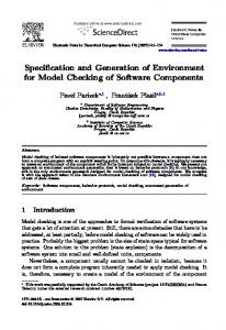
N
N 109
9
10
8
10
10
107
107
106
10
8
6
10
5
105
104
104
103
10
3
-500-400-300-200-100 0 100 200 300 400 500 x [µm]
-20 -15
-10
-5
0
5
10
15 20 y [µm]
Figure 2: Transverse beam profiles at the BDS entrance. we expect that 6 × 10⁹ particles hit the spoilers at each train crossing. Based on earlier estimates [3], we expect that this will result in roughly 105 secondary muons.
5 Estimates and simulations for CLIC Detailed estimates and simulations for CLIC were presented at the EPAC’06 [4] based on a 14 km long LINAC section with gradients of 150 MV/m and a 2.5 km long beam delivery section. These estimates have been updated for the CLIC’07 workshop using the more recent CLIC parameters based on a 21 km long Linac with 100 MV/m gradient and 2.75 km beam delivery system. Numerical estimates are based on the assumption that the pressure of the restgas is equivalent to 10 nTorr of CO at room temperature, both in the LINAC and q the BDS. As minimum scattering angle relevant for halo production, we used θ = ǫ/β, based on a conservative value of 5 nm for the vertical emittance at an average βy = 100 m. Integrated over the Linac, the probability for Mott scattering is then P = 1.16 × 10⁻³ , see also Table 2. The total probablility for the 2.75 km long BDS is P = 6.02 × 10⁻⁵ . For the sum of LINAC and BDS we get a scattering probability of P = 1.2 × 10⁻³. The probability for inelastic scattering with a fractional energy loss kmin > 0.01 is much smaller, about 2.1 × 10⁻¹³ m both in the LINAC and BDS. Summing up over the full length, we get a probability for inelastic scattering for the combined LINAC and BDS system of 5 × 10⁻⁹ . The fraction of particles which will be lost at collimators is obtained from the detailed simulation. The results depend on collimator positions and settings. Based on preliminary collimation studies and simulations under rather idealistic assumptions, we roughly expect that a fraction of about 2 × 10⁻⁴ of all particles will have large amplitudes and
8
Table 2: Analytical estimates for elastic beam-gas scattering with scattering angles above 1 σ of the beam divergence for a constant normalized emittance of 5 nm at βy = 100 m. ρ is the density of CO molecules per m3 and P the scattering probability per electron and meter. Location E Gas ρ σel P GeV m−3 barn m−1 LINAC 9 CO 3.2 × 10¹⁴ 1.1 × 10⁸ 3.6 × 10⁻⁶ BDS 1500 CO 3.2 × 10¹⁴ 6.8 × 10⁵ 2.2 × 10⁻⁸ hit the spoilers in the BDS section. With 1.24 × 10¹² particles per train, this would translate into a flux of 2.4 × 10⁸ particles per train impacting on the spoilers. At 1.5 TeV, we expect that a fraction of about 9 × 10⁻⁴ of these particles produce secondary muons, resulting in a flux of about 2 × 10⁵ muons per train, many of which would be seen as background in the detector in the interaction region. Reducing the muon flux would require very massive shielding, of the order of 100 m of (magnetised) tunnel fillers, to be effective [3]. We believe therefore that it is very important in CLIC to include halo studies in the design and to minimize halo production or remove halo already at low energies.
6 Summary and outlook We believe, that the halo and tail generation work, which was set up and supported as task within EuroTeV workpage 6 on integrated luminosity performance studies has already been and will also remain in future very useful for linear collider studies and designs. Our work and in particular the generic HTGEN code, provide a solid basis for halo and tail estimates and simulations and can be and already have been used to guide vacuum specifications and collimation designs. The program and the documentation are well advanced and will continue to be used and further developed beyond the work set up within EuroTeV, which formally stops at the end of 2008 as EuroTeV task, and which is summarized in this report. The next step, for which the work has already started in collaboration with the Karlsruhe university and reasearch centre, is to extend our simulations to a wider energy range. While our studies were originally mostly targeted towards higher energies as relevant in the LINAC and beam delivery sections, we are now going to extend and apply them to lower energies as relevant for test facilities and the CLIC drive beam. In addition to benchmarking HTGEN with other codes, this will also open up possibilities to compare HTGEN based simulations with actual measurements in the near future.
9
Acknowledgement This work is supported by the Commission of the European Communities under the 6th Framework Programme ”Structuring the European Research Area”, contract number RIDS-011899.
References [1] H. Burkhardt. General machine background in future e+ e− colliders. Proc. of the Internat. Workshop on Linear Colliders, LCWS99, 1999 Sitges/Barcelona and CERN-SL-99-057-AP. [2] L. P. Keller. Muon background in a 1-tev linear collider. Contributed to 5th International Workshop on Next-Generation Linear Colliders, Stanford, CA, 13-21 Oct 1993, SLAC-PUB-6385. [3] G. A. Blair, H. Burkhardt, and H. J. Schreiber. Background simulation for the CLIC beam delivery system with Geant. Proceedings of EPAC 2002, Paris, France, pp. 449-451. [4] H. Burkhardt, L. Neukermans, and J. Resta Lopez. Halo and tail generation studies for linear colliders. Proc. EPAC 2006, CLIC-Note-668 (CERN-AB-2006-054), EUROTeV-Report-2006-028. [5] H. Burkhardt, L. Neukermans, A. Latina, D. Schulte, I.V. Agapov, G.A. Blair, and F. Jackson. Halo estimates and simulations for linear colliders. Proc. 2007, CLIC-Note-714 (CERN-AB-2007-045) and EUROTeV-Report-2007-064. [6] H. Burkhardt, I. Reichel, and G. Roy. Transverse beam tails due to inelastic scattering. PRSTAB, 3:091001, 2000. [7] H. Burkhardt et al. Halo and Tail generator package HTGEN with links to code, publications and presentations, http://hbu.home.cern.ch/hbu/HTGEN.html [8] S. Agostinelli et al. Geant4: A simulation toolkit. Nucl. Instrum. Meth., A506:250– 303, 2003. [9] A. Latina, H. Burkhardt, P. Eliasson, L. Neukermans, J. Resta Lopez, G. Rumolo, D. Schulte, and R. Tomas. Recent improvements of placet. Proc. EPAC 2006 and EUROTEV-REPORT-2006-030. [10] D. Krucker, F. Poirier, and N. Walker. An ILC main linac simulation package based on Merlin. Proc. EPAC 2006 and EUROTEV-REPORT-2006-071. [11] H. Burkhardt. Monte Carlo Generation of the Energy Spectrum of Synchrotron Radiation. CLIC-Note 2007-709 and EUROTeV Report 2007-018.
10
[12] H. Burkhardt. Monte Carlo Simulation of Beam Particles and Thermal Photons. SL Note 93-73 (OP), CERN, July 1993. [13] Ijaz Ahmed, Helmut Burkhardt, and Miriam Fitterer. User Manual for the Halo and Tail generator HTGEN. EUROTeV-Memo-2008-003. [14] W.S.C. Williams. Nuclear and Particle Physics. Oxford University Press, 1991. [15] R. Brinkmann. Presentation at BDIR-2000 in Daresbury. [16] The international linear collider global design effort baseline configuration document; available from http://www.linearcollider.org/wiki/doku.php.
11