In conventional register renaming schemes, register releasing is conservatively .... (N) and name of the structure that reorders the uncommitted instructions.
Hardware Schemes for Early Register Release Teresa Monreal†, Víctor Viñals†, Antonio González* and Mateo Valero* †
Departamento de Informática e Ing. de Sistemas Universidad de Zaragoza e-mail: {tmonreal,victor}@posta.unizar.es
Abstract Register files are becoming one of the critical components of current out-of-order processors in terms of delay and power consumption, since their potential to exploit instruction-level parallelism is quite related to the size and number of ports of the register file. In conventional register renaming schemes, register releasing is conservatively done only after the instruction that redefines the same register is committed. Instead, we propose a scheme that releases registers as soon as the processor knows that there will be no further use of them. We present two earlyreleasing hardware implementations with different performance/complexity trade-offs. Detailed cycle-level simulations show either a significant speedup for a given register file size, or a reduction in register file size for a given performance level.
1. Introduction Dynamic scheduling, also known as out-of-order execution, allows instructions to be executed as soon as their operands are ready bypassing prior instructions in the sequential program order. This is achieved by means of register renaming [11][21], which remove false registerdependences (output and anti dependences) creating a new register version for each register destination. Register versions are written only once, and read as many times as needed to satisfy flow dependences. Among the versions of a given register kept inside the processor, all but the oldest one are speculative and could become useless if an exception or a branch misprediction occurs. Register versions can either be centralized in a single file, or distributed among different data structures. In this work, we are interested in improving the utilization of merged register files [21]. That is, register files that merge together committed and non-committed versions, as happens in processors such as MIPS R10K [25]. To differentiate ISA registers from rename registers (holding versions), they are called logical and physical registers, respectively. To keep pace with the general processor trend (increasing number of in-flight instructions and functional units), register files are required to offer more registers, to be reachable in a single cycle and from more ports [18][19]. All of this, should be done ideally without compromising
*
Departament d’Arquitectura de Computadors Universitat Politècnica de Catalunya e-mail: {antonio,mateo}@ac.upc.es
the growing frequencies of the out-of-order execution core, and further consuming a reasonable amount of power [26]. In fact, Simultaneous Multithreading, a feasible path for such future processors, can only achieve all its performance potential with large register files able to keep values from several threads [23]. Many works assume that the register file can impact on the processor cycle time [1][5][6][7] and is one of the most power-consuming structures [26]. Its size (P registers) and number of ports (T read and write ports) determine silicon area, power consumption and access time [20]. Therefore, a direct way to reduce register file delay is reducing P, T, or both. To do that, common approaches trade off IPC decrease against IPS (instructions per second) increase. A first approach address the internal file organization basically without modifying the interface with the functional units. Some examples are the Minimally-Ported Banked register file [1] or the two-level register hierarchy managed in an inclusive [5] or exclusive [1] way. A second approach suggest clustered microarchitectures, where the register file is sliced in banks, each bank directly feeding a functional unit cluster. Many of these solutions have been targeted to decentralize several critical structures, not only the register file. One example is the DependenceBased architecture [18], where each bank is a complete copy of the register file as in the Alpha 21264 two-cluster case [12]. Other examples are the Multicluster architecture [7] (each bank is assigned a subset of the ISA registers) and related optimizations on assignment heuristics [2][4], or the Energy-Efficient Multicluster architecture [26] (each bank contains a subset of physical registers). Finally, a third approach aims to act on the mechanism that controls the allocation or release of physical registers, trying to reduce the average number of required registers. In general, after applying some control improvement, a reduction in P is enabled without any IPC loss. Some works suggest delaying the allocation of registers until the functional units supply the results, either in a restricted form (dynamic result renaming [24]) or in a more flexible way (virtual registers [16]). It is known that the conventional way of releasing is inefficient since registers are retained longer than strictly needed [17][6]. A previous approach to release registers early was suggested by Moudgill et al. in [17]. Their
Proceedings of the International Conference on Parallel Processing (ICPP’02) 0-7695-1677-7/02 $17.00 © 2002 IEEE Authorized licensed use limited to: Universidad de Zaragoza. Downloaded on January 13, 2010 at 08:06 from IEEE Xplore. Restrictions apply.
implementation is based on counters of pending reads but does not support precise exceptions. Afterward, Farkas et al. measured the gains of an imprecise early release policy, but no implementation was proposed [6]. Our contribution is to introduce and evaluate, hardwareonly mechanisms devoted to release physical registers earlier, which take into account branch speculation and enable precise exception recovery. Our proposals can be applied to reduce the register file size, and so its access time, at the expense of introducing overhead structures that are not on critical timing paths. Alternatively, for register files that are already small enough to fit in the cycle time we can maintain P and use early release to increase IPC. The paper is structured as follows: Section 2 presents the background for building the mechanisms and evaluates their potential gain. Section 3 focuses on a simple but limited mechanism, and Section 4 extends it taking into account control speculation. Methodology and results are presented in Section 5. We discuss related work in Section 6 and offer concluding remarks in Section 7.
arises IPC may temporarily drop. We say that a loose register file has P » L + N. On the other hand, we call the second alternative a tight register file because a sequence with less than N instructions writing P-L registers runs out of physical registers, forcing the processor to stop filling the issue window. Intel P4 has a loose register file (128 phys. » 8 logical + 126 uncomm.) unless the inflight flag registers were renamed using physical registers. In this case the file could become very tight. Loose designs exploit all the ILP attainable by allowing the whole instruction window to be filled under any condition, whereas tight designs may contribute to reduce processor cycle time if the register file is located in a critical timing path. We assume a renaming mechanism similar to that of processors in Table 1. Figure 1 shows the involved components: Map Table, Reorder Structure, Free List, and In-Order Map Table. The Map Table (MT) keeps the logical to physical mapping [11]. The destination physical register identifiers (pd) are supplied by the Free List.
2. Conventional Release Policy
Table 1. Out-of-order processors with merged register files. MIPS R12K
ALPHA 21264
INTEL P4
P = # of Phys. Registers in Int File T = # of Read and Write Ports
64 7R 3W
2x 80 2x (4R 6W)a
128 n.a.
P = # of Phys. Registers in FP File T = # of Read and Write Ports
64 5R 3W
72 6R 4W
128 n.a.
80 In-Flight Window
126 mops Reorder Buffer
N = Reorder Structure Size Reorder Structure Name
32 Active List
48 Active List
Free List
Reg
First, we point out that register files can be dimensioned either in a loose or in a tight way. Next, we review the conventional policy for allocating and releasing registers and then, we give experimental evidence of its low efficiency. To exemplify, we show four processors with merged register files, namely MIPS R10/12K [25][8], Alpha 21264 [12], and Intel P4 [9]. Table 1 shows their number of physical registers (P) and ports (T). It also shows the size (N) and name of the structure that reorders the uncommitted instructions. MIPS R10K
MapTable
Instr
a. The integer register file has been replicated because a single file with 14 ports (8 read plus 6 write) could not be implemented without compromising performance.
MIPS R10K supports up to N=32 uncommitted instructions in its Active List. Since MIPS ISA has L=32 logical integer registers and P=64 physical registers, this processor never stalls because of the lack of physical registers (P = L + N). By contrast, in MIPS R12K and Alpha 21264 a long enough instruction sequence without branches and stores can stall decoding (P < L + N). If this situation
fetch
In-Order MapTable
pd old pd
rd
old pd
rd
pd
ROS Reorder Structure rd = rs1 op rs2
...
old_pd
rd
commit
...
pd
current-version physical register identifier
previous-version physical register identifier logical register identifier
Figure 1. Allocate/release mechanism. Detail of a ROS entry.
The Reorder Structure (ROS) keeps information about all uncommitted instructions in program order. We assume a FIFO behavior implemented with SRAM and read/write pointers. Therefore, a ROS address can be used as a unique instruction identifier. While instructions are decoded, three fields are written into the ROS bottom entry: . The identifier of the physical register containing the previous version (old_pd) is read from MT. The logical and physical identifiers of the destination register (the current version) are, respectively, rd and pd1. As instructions commit, the pd and rd entries are used for updating the In-Order Map Table (IOMT), and the old_pd identifier is added to the Free List. This is the way conventional release acts [17]. The IOMT keeps the logical to physical architectural mapping. When an exception has 1. Each ROS entry stores the result identifier, as in an indirect Reorder Buffer. But it also has the previous-version identifier, as in an indirect History Buffer [22]. So we adopt ROS as a more general term.
Proceedings of the International Conference on Parallel Processing (ICPP’02) 0-7695-1677-7/02 $17.00 © 2002 IEEE Authorized licensed use limited to: Universidad de Zaragoza. Downloaded on January 13, 2010 at 08:06 from IEEE Xplore. Restrictions apply.
Empty
instruction decode
value computed
(b) Allocated
Free
Ready last-use commit
next-version commit
Idle
number of integer registers
Allocated 100
empty
ready
idle
80 60 40 20 0 comp
gcc
go
li
perl
Amean
swim
hydr
Amean
integer 100
number of FP registers
to be serviced, the IOMT avoids rolling back the ROS to recover the architectural state. In Intel P4, the IOMT is called Retirement Register Alias Table [9]. Physical registers can be Free or Allocated, and Allocated registers can be either Empty, Ready, or Idle according to the usefulness of their content (Figure 2a). We say a physical register is Empty from the moment it is allocated until it is actually written. We say a register is Idle from the commit of the instruction using that register for the last time, until the commit of the instruction producing the next version. An Allocated register is Ready when it is neither Empty nor Idle. Figure 2b shows the execution of a program sample, where the physical register p7 experiences every state. Instruction i writes logical register r1, which is renamed to physical register p7. Later on, instruction LU (last-use) reads r1 for the last time. Finally, instruction NV (nextversion) rewrites r1. As Figure 2b shows, p7 will not be released until instruction NV commits, being it Allocated and Idle from LU commit to NV commit.
80 60 40 20 0 mgri
tomc
appl
floating point
Figure 3. Number of Allocated registers being either in Empty, Ready, or Idle states in a conventional renaming.
programs. The experimental framework is detailed in Section 5. On average, for our workload, the late release policy of conventional renaming increases the number of used registers (empty + ready) by 45.8% for integer programs, and by 16.8% for FP programs, as shown by the idle bar in Figure 3.
3. Basic Mechanism p7 state
FREE
ALLOCATED
EMPTY
i:
r1 = ...
D
FREE
READY
Ex
IDLE
C
r1 renamed to p7
(a) LU: r3 = r2 + r1
D
C
no use of r1
NV: r1 = ...
D
C p7 is released
Figure 2. Breakdown of the ALLOCATED state and example of state evolution of the physical register p7.
This policy performs poorly because of two reasons: • Registers are allocated too early. Empty registers do not contain information. Mechanisms which delay allocation try to remove this state [24][16]. • Registers are released too late. Idle registers are useless. Section 3 and Section 4 focus on mechanisms directed to release registers entering the Idle state quickly. Precise recovery will be covered in detail in Section 4.3. Figure 3 shows the average number of Allocated registers being either in Empty, Ready or Idle states in conventional renaming for a SPEC 95 subset. We assume a processor with a tight register file with 96 physical registers (L=32, P=96int + 96FP, N=128). We consider only integer registers for integer programs and FP registers for FP
Figure 4.a shows an example where LU instruction reads for the last time r1. Figure 4.b shows the less frequent case where LU instruction writes r3 without further use until the NV instruction comes. The basic idea is to tie up the physical register release with the commit of the instruction using it for the last time in program order. To do so, first we identify the LU instruction (when decoding the NV instruction) and second, an early release of the physical register is scheduled for the LU instruction commit. Note that, if the LU instruction is already committed when decoding its NV pair, the corresponding physical register can be released immediately. If a speculative NV instruction has to be squashed we need to undo its scheduling. Here, two distinct cases arise: • Case 1. There are no pending branches between instructions LU and NV. This occurs if both LU and NV instructions belong to the same basic block. It can also occur if LU and NV instructions are in different basic blocks but all the intervening branches are already executed and their conditions and target addresses verified at NV decode time. • Case 2. When decoding the NV instruction, there are still pending branches between it and its previous LU instruction pair.
Proceedings of the International Conference on Parallel Processing (ICPP’02) 0-7695-1677-7/02 $17.00 © 2002 IEEE Authorized licensed use limited to: Universidad de Zaragoza. Downloaded on January 13, 2010 at 08:06 from IEEE Xplore. Restrictions apply.
i: r1 = ...
;r1 renamed to p7
LU: r3 = r2 + r1 no use of r1
LU: r3 = r5 + r9;r3 renamed to p7
logic
no use of r3
Last Uses Table
Map Table
reg. #
phy. reg. #
ROSid of LU instr. src/dst
ROSid
NV: r3 = ...
Kind
commit
C
NV: r1 = ... (a)
Extended ROS
(b) r1
Figure 4. Two examples where the physical register p7 can be released when the LU instruction commits.
This Section introduces an implementation of a basic mechanism dealing only with the first case. Later on, Section 4 extends it to cover also the second case. The basic mechanism will only schedule early releases if an LU-NV instruction pair is safely recognized when the NV instruction is decoded (Case 1). In the remaining cases, the conventional releasing policy outlined in Section 2 is applied. To implement the basic mechanism any instruction should have the ability to release its physical source (Figure 4.a) and destination (Figure 4.b) registers at commit time. The ability to disconnect the (conventional) release of the previous-version register is also needed, in case such register is going to be released early.
3.1. Hardware Resources Figure 5 shows an implementation based on adding fields to the Reorder Structure (ROS) and Map Table (MT). The extended ROS has now the following fields: • r1, r2, rd: logical register identifiers. • p1, p2, pd: physical register identifiers. • old_pd: physical identifier of the previous-version destination register. • rel_old: previous-version release bit. If reset at commit time, old_pd will not be released. • rel1, rel2, reld: early-release bits for p1, p2, and pd, respectively. When set at commit time, they force the corresponding physical register release. At decode/rename time the previous-version release bit is set and all the early-release bits are reset. The MT extension is better described as a separate structure called Last-Uses Table (LUs Table). LUs Table identifies instructions using a given register for the last time. Every entry has the following fields: • ROSid: for each logical register, it keeps the identifier of the instruction using it for the last time, that is, the LU instruction. • Kind: kind of register use: src1, src2, dst. • C: reports whether the LU instruction is still in the pipeline (C=0) or has already been committed (C=1). Once this table supplies the ROS identifier of an LU instruction, an early release can be scheduled by setting the corresponding early-release bit. As is the case for MT, we assume that an LUs Table copy is made at each branch prediction, so that a branch misprediction recovery can retrieve the proper copy [10].
r2
Logical Register id.
rd
old_pd rel_old
p1
commit
p2
Physical Register id.
pd rel1 rel2 reld
early-release bits
Figure 5. Basic mechanism. The shaded areas highlight the fields added to extend the ROS.
3.2. Control Control steps are located at decode, rename and commit stages. We describe them in reverse order. Commit: C bit update and register release. When instruction i commits, its logical register identifiers are available in the ROS head. We index LUs Table with these identifiers and read the ROSid fields comparing them with the i identifier and, where a match is found, the commit bit is set (C=1). So, we record that a potential LU instruction has been committed2. Note that this action on bit C has to be extended to all LUs Table copies to achieve a proper branch misprediction recovery. In parallel, the release bits drive physical register release. Up to four identifiers can be supplied to Free List: p1, p2, pd (early release) and old_pd (conventional release). Renaming 1: LUs Table update. To record register uses properly, up to three LUs table entries have to be updated for each renamed instruction. The instruction ROS address is kept in ROSid, the register role is kept in Kind (src1, src2 or dst), and the C bit is reset. So, the identity of the instruction using a given logical register for the last time is recorded in program order. Figure 6.a shows an example of this step. Renaming 2: release scheduling or register reuse. For each instruction having a destination register -a NV instruction-, this step ends either scheduling an early release or reusing the previous-version physical register. To do so, the logical destination register of NV is used to look up the LUs Table. Let’s call LU the found instruction, and LUid its ROS address. Next, if there are no branches pending verification between the NV and LU instructions, we proceed as follows: 2. Alternatively, we can access associatively to all ROSid fields with the i identifier, setting bits C in the entries where a match is found. With this support, the r1 and r2 fields in the ROS would no longer be needed.
Proceedings of the International Conference on Parallel Processing (ICPP’02) 0-7695-1677-7/02 $17.00 © 2002 IEEE Authorized licensed use limited to: Universidad de Zaragoza. Downloaded on January 13, 2010 at 08:06 from IEEE Xplore. Restrictions apply.
(r9 last-use)
LU: r3 = r5 + r9 . . .
(r9 next-version)
rename
p8 = p3 + p7
NV: r9 = ... LUid
4.1. Hardware resources
NVid
r5
ROSid
r3
r3 r5
r9
p8 p3
p7
LUid LUid
LUid
0 1
2
ROS
r9
Kind C 0
r9 p7
old_pd
0
0
rel_old
commit
p3
0
p7
physical regs.
p8
Map Table
LUs Table
(a)
(b)
rel1 rel2 reld
1
commit of the NV instruction. This saves the storage required for the old_pd and rel_old fields in the ROS.
early-release bits
Figure 6. a) Map Table and LUs Table after renaming instruction LU. b) Decoding of instruction NV: the LUs Table is looked up, NV disables itself p7 release by resetting rel_old, and an early release of p7 is scheduled for instruction LU.
• If LU instruction is still in the pipeline (C=0), we set in ROS the suitable early-release bit: relx[LUid]=1, where x is 1, 2 or d. We also reset the previous-version release bit for NV: rel_old[NVid]=0. Figure 6.b illustrates this step. • Otherwise, if LU instruction is already committed (C=1) we can release immediately the physical register indicated in the Map Table, resetting as before the rel_old release bit. In fact, we can reuse the same physical register leaving the mapping untouched and not reclaiming any new register.
3.3. Performance The basic mechanism is simple but its ability to release register earlier is limited. Its performance is noticeable with tight register files. With 64int+64FP and 48int+48FP physical registers, it achieves an average speedup over conventional release of around 3% and 6%, respectively, for numerical programs. For integer programs, the average speedup is negligible. However, processors with very tight register files benefit from early release in both application types: a 40int+40FP register configuration experiences 5% speedup for integer codes, and 9% for floating-point. Simulation details are shown in Section 5.
4. Extended mechanism In the basic mechanism any time a register redefinition is decoded with some previous unresolved branch, the earlyrelease opportunity is lost. We show next an extended mechanism that overcomes this problem by handling conditional releases. The idea is quite similar to that of a branch stack of Map Table copies used to recover from branch misprediction. The proposed implementation definitively disconnects the register release from the
Figure 7 shows all the components making up the extended mechanism. From the basic mechanism, we maintain the Physical Register Identifiers and the Early-Release bit array, calling them PRid and RwC0 (Release when Commit), respectively. The key structure is a Release Queue (RelQue). In the vertical dimension this queue acts as a FIFO with as many levels occupied as branches pending confirmation are. Therefore, it has to be sized with as many levels as pending branches the processor supports. A given RelQue level keeps schedulings of conditional releases. A release is conditional whenever the originating NV instruction is speculative. Level number n keeps the schedulings depending on the validation of the n oldest pending branches. Each level in the RelQue comprises two structures: a bit-vector RwNSx (RwNS1, RwNS2, ...) and a 3-bit array RwCx (RwC1, RwC2, ...). RwNSx (Release when Non-Speculative), keeps the conditional releases for the already committed LU instructions in a decodified form (1 physical reg. = 1 bit). RwCx (Release when Commit), keeps the conditional releases to be synchronized with the commit of LU instructions still in the pipeline. The identity of the physical register to be released is kept codified in PRid. To deal with the in-order commit requirement, all the RwCx structures have to support right to left shift operation in the horizontal dimension, as the ROS has. ROS size p1
PRid
p2
commit
Physical Register identifiers
pd rel1 rel2 reld
RwC0
early-release bits
RwC1
RwNS1
fixed HEAD
RwC2
RwNS2 commit
TAIL
RwCmax
RwNSmax
rel1 rel2 reld
# Phys. Regs. bits
RELEASE QUEUE
Figure 7. Extended mechanism.
4.2. Control The basic idea is to stack up a new level in the RelQue each time a branch is decoded. The NV instructions which are decoded after that branch look up the LUs table, identifying LU instructions and scheduling releases, in RwNSx if the
Proceedings of the International Conference on Parallel Processing (ICPP’02) 0-7695-1677-7/02 $17.00 © 2002 IEEE Authorized licensed use limited to: Universidad de Zaragoza. Downloaded on January 13, 2010 at 08:06 from IEEE Xplore. Restrictions apply.
LU instruction is already committed, otherwise in RwCx. As branch predictions are confirmed, the conditional releases on both RwNSx and RwCx move towards RwC0. In a misprediction the corresponding entry in the RelQue and all the younger ones are cleared, squashing the conditional releases previously scheduled by the mispredicted path. Next we show in detail the control steps needed to manage the RelQue and release registers. We assume branches can be verified out of order. For the sake of clarity, we assume that the RelQue FIFO head is at a fixed location, marking the last occupied level with the pointer TAIL. • Step 1. Branch instruction decode. A new level with all its bits reset is appended to the RelQue by simply increasing the TAIL pointer. • Step 2. Speculative NV instruction decode. The RelQue level pointed by TAIL is marked with a conditional release for a given physical register p. Two cases can arise for an NV instruction with n pending branches in front of it: first, if the LU instruction is already committed, the bit vector RwNSn is marked (RwNSn[p]=1). Second, the bit array RwCn is marked (RwCn[LUid]relx=1, where x = 1, 2 or d). • Step 3. Branch misprediction. The prediction for the branch number n was wrong. All levels in the RelQue from n to TAIL are cleared. Therefore, TAIL is left pointing to the n-1 level. • Step 4. Branch confirmation. The prediction for the pending branch number n is found to be correct. All the releases located between the entries n and TAIL are moved towards RwC0 (see example in Figure 8.a). At the same time entry n is ored with entry n-1. There is some additional work to case n=1 which will be dealt with later on. • Step 5. Commit effects in the Release Queue. The RelQue, also needs a FIFO right-to-left management in the RwCx structures. So, all the bits of every level in the RwCx bit arrays have to be shifted left any cycle as many positions as instructions are committing. An LU instruction can commit before its NV instruction pair becomes non-speculative. In this case, all schedulings of committing instructions are moved from the commit head of RwCx to RwNSx because the branch prediction could still be confirmed (see Mark in Figure 8.b). This movement requires decoding the register identifiers located at the ROS head. • Step 6. Physical register releasing. Putting all the previous steps together, registers can be released at the commit stage of LU instructions and each time the oldest branch is confirmed. In the first case, the registers scheduled in the RwC0 entries of the committing instructions are released (see Commit Release in Figure 8.b). In the second case, the registers scheduled in RwNS1 are released when the
PRid RwC0 branch number 2 is verified
RwC1
RwNS1
or
RwNS2
or
RwC2
mov
mov
mov
mov
-1 TAIL
RELEASE QUEUE
(a)
committing instructions PRid
Commit Release
RwC0
Mark
RwC1
RwNS1
RELEASE QUEUE
(b)
PRid Branch-Confirm Release
RwC0 or
RwNS1 RwNS2
mov
RwC1 RwC2
mov
oldest branch is verified
mov mov
-1
(c)
RELEASE QUEUE
TAIL
Figure 8. a) The second oldest branch is confirmed, b) RwNSx marking and Commit Release, c) oldest branch confirmation triggers a branch-confirm release.
oldest branch prediction is confirmed (see BranchConfirm Release in Figure 8.c). This is the additional work we mentioned for n=1 in Step 4. With regard to non-speculative NV instruction decoding, the same rules as in he basic mechanism apply: if the LU instruction found is already committed, then releasing proceeds immediately, otherwise the release is scheduled in the RwC0 level. Finally, note that the total number of set bits in the whole RelQue is bound by the ROS size. Indeed, there are exactly as many bits set as non-committed instructions with destination registers are. Therefore, if we implement the RelQue as a true two-dimension shift register, most of the time the shifted values are zeroes. This is because when estimating the consumption of the mechanism we can safely neglect the RelQue contribution (Section 4.4).
4.3. Precise exceptions Between the last-use of a logical register r (LU instr.) and its closest redefinition (NV instr.), an exception can appear once the current version of r has been lost by an early release action.
Proceedings of the International Conference on Parallel Processing (ICPP’02) 0-7695-1677-7/02 $17.00 © 2002 IEEE Authorized licensed use limited to: Universidad de Zaragoza. Downloaded on January 13, 2010 at 08:06 from IEEE Xplore. Restrictions apply.
The exception handler saves the PC of the instruction to execute (or re-execute) it later. It also saves all the logical registers into the Process Control Block if the exception requires a context switch. In doing this, the handler could store for r a value that may be different from the last value stored in that logical register. Later on, when context is restored the same -incorrect- value is stored back in r. The point here is that the value attached to r does not really matter because the early releasing hardware only discards a version if it is guaranteed that the first use of r is a write. Therefore, we can conclude that our system does not strictly hold the usual condition to be precise: “An interrupt is precise if the saved process state corresponds with a sequential model of program execution where one instruction completes before the next begins” [22]. However, this definition of precise exceptions is sufficient but not necessary to guarantee a proper recovery. The optimization we propose is safe in that these incorrect values are guaranteed not to be used by the program. Similar optimizations in software were proposed elsewhere [13].
example, we can move from a 64int+79fp to a 56int+72fp configuration while maintaining IPC (see next Section). When comparing the energy consumption of these two alternatives, we have the following: Econv (RF64int+RF79fp) = 3850pJ, and for early release: Eearly (RF56int+RF72fp+2xLUsTable) = 3851pJ. Therefore, the energy balance is neutral. Regarding storage cost, it is quite affordable in the context of a highperformance microprocessor. As an example, an Alpha 21264 will need about 1.22 KBytes to support the extended mechanism (ROSsize = 80, physical identifier = 8bits, # of physical regs. = 80+72 = 152, # of pending branches = 20). The int+fp LUs Tables will further add around 128B.
4.4. Implementation remarks
Table 2. Processor parameters.
The key structure of the Extended mechanism is the LUs Table. It can be implemented as a heavily ported SRAM, requiring 32 read and 24 write ports for an 8-way superscalar processor (P=32 entries, T=56 ports, word size= 9 bits). To assess its impact on cycle time and consumption, we use the delay and power model of Rixner et al. for a 0.18mm technology [20]. Figure 9 shows the access time and energy for the LUs Table. The same figures are also computed for the integer and FP register files considered for the aggressive processor evaluated in the next Section (Tint = 44, Tfp =50), varying P from 40 to 160 physical registers. As can be seen, the LUs Table delay is clearly below any register size. In particular, it is a 26% less than that of the smaller integer file. With regard to consumption, the LUs Table requires only a 20% of the least demanding file. We can use early release as a means to reduce register file requirements for a given performance level. For
Parameter Fetch width L1 I-cache Branch prediction ROS size Functional Units (latency) Load/Store Queue
5000
2
(a)
(b)
4500
1,8
FP LUsT
0,98 ns
1
Physical Registers L1 D-cache L2 Unified Cache Main Memory Commit width
2000
int
1500
INT FP LUsT
1000
193,2 pJ
88
56
64 72 80
96
10 4 11 2 12 0 12 8 13 6 14 4 15 2 16 0
72
80 88
48
56 64
40 48
0
number of registers
Value 8 instructions (up to 2 taken branches) 32 KB, 2-way set-associative, 32 byte lines, 1 cycle hit time 18-bit gshare, speculative updates, up to 20 pending branches 128 entries 8 Simple int (1); 4 int mult (7); 6 simple FP (4); 4 FP mult (4); 4 FP div (16); 4 load/store 64 entries with store-load forwarding out-of-order issue. Loads are executed when all previously store addresses are known 40-160 int / 40-160 FP (32 int / 32 FP logical) 32 KB, 2-way set-associative, 64 byte lines, 1 cycle hit time 1 MB, 2-way set-associative, 64 byte lines, 12 cycles hit time unbounded size, 50 cycles access time 8 instructions
Ten randomly-chosen benchmarks from the Spec95 suite are used: five integer and five FP programs. All programs were simulated to completion (by changing the reference inputs) excepting tomcatv, for which the initial part reading a huge input file was skipped. Table 3 lists the programs, inputs, and the number of executed instructions.
2500
500 0,8 40
Issue mechanism
3000
96 10 4 11 2 12 0 12 8 13 6 14 4 15 2 16 0
Access Time (ns)
INT
1,2
Energy Consumed (pJ)
3500
1,4
Early register releasing has been evaluated by using SimpleScalar v3.0 [3]. The out-of-order simulator has been modified to include physical register files (integer and FP) which are handled by the considered release policies. The main parameters of the microarchitecture are in Table 2.
Table 3. Used benchmarks. We ran Compaq/Alpha Fortran and C compilers with -O5 for Fortran and -O4 -migrate for C.
4000
1,6
5. Evaluation and results
number of registers
Figure 9. Access time and energy consumption of LUs Table and register file vs number of registers.
FP
Application compress gcc go li perl mgrid tomcatv applu swim hydro2d
Inputs exec inst (M) 40000 e 2231 170 genrecog.i 145 99 146 7 queens 243 scrabbl.in 47 test, replacing two first lines to 5 and 18 169 test 191 train, changing dt=1.5e-03 and nx=ny=nz=13 398 train 431 test (replacing ISTEP=1) 472
Proceedings of the International Conference on Parallel Processing (ICPP’02) 0-7695-1677-7/02 $17.00 © 2002 IEEE Authorized licensed use limited to: Universidad de Zaragoza. Downloaded on January 13, 2010 at 08:06 from IEEE Xplore. Restrictions apply.
Integer
2,8
Integer
2,4
2,8
2,8
2,2
2,6
2,6
2
2,4
2,4
1,8
2,2
2,2
IPC
1,4
1,8
1,2
2 1,8
conv 1,6
160
40
48
56
64
72
80
88
96 104 112 120 128 160
number of registers
number of registers
extended
2
120
2,2
1
112
basic
1,2
1 96
2,4
1,4
1,2
88
conv
1,6
extended 1,4
104
FP
Hm
80
perl
72
li
64
2,6
go
56
gcc
48
comp
basic
128
1 2,8
2
40
IPC
1,6
IPC
3
2,6
IPC
FP
3
Figure 11. IPC harmonic mean vs number of physical registers for conv, basic, and extended.
1,8 1,6 1,4 1,2 1 mgr
tomc
appl
swim
hydr
Hm
Figure 10. IPC of early releasing (basic and extended mechanisms) vs. conventional (conv) for 48+48 register file.
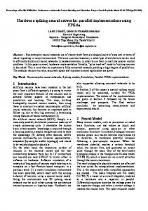
5.1. Results First, we observe the performance impact of early releasing in a processor with very tight register files of 48int + 48FP registers. Figure 10 shows the average number of instructions committed per cycle (IPC) for each benchmark, as well as the harmonic mean (Hm) for integer and FP programs. Conventional releasing (conv) is compared with our basic and extended mechanisms (basic and extended, respectively). The performance gains with early releasing for FP codes are much more significant than for integer programs. Basic provides an average speedup over conv of 6% for FP codes, whereas for integer benchmarks the speedup is negligible. However, extended provides an average speedup over conv of 8% and 5% for FP and integer codes, respectively. These are expected results, since in general FP programs have a much higher register pressure and integer programs are branch-intensive. Remember that branches limit the effectiveness of early releases by delaying their effects until the corresponding verification is done. Next, we will show how early release performs under different conditions of register pressure. We consider a wide range of register file sizes, plotting the achieved IPC for all policies in Figure 11. A first remarkable point is the low register pressure in integer codes. For them, a loose register file has no sense, with or without early release. Excluding loose designs, early release always has a performance advantage, being the difference more sustained for FP codes. Moreover, when comparing basic
with extended, we can realize that extended is specially well suited for integer codes, whereas for FP codes both mechanisms behave similarly. FP codes experience significant gains with tight register files between 40 and 104 registers. In this range, extended gives a speedup smoothly decreasing from 10% to 2% (from 9% to 1% in basic). However, programs with high register pressure can experience much larger figures with extended; for instance hydro2d gets 12% with 40 registers and tomcatv gets (16%, 12%, 8%) with (40, 56, 88) registers, respectively. Integer codes benefit from early release, but only for very tight register files, roughly between 40 and 64 registers. Within this range, extended gives a speedup decreasing from 11% to 2% (from 5% to 0% in basic). Alternatively, we can use early release as a means to reduce register requirements for a given performance level. Table 4 shows several register configurations giving the same IPC, along with the saved storage. Table 4. Register file sizes giving equal IPC. FP codes
int codes
conv
extended
saved %
conv
extended
saved %
69
64
7.2%
64
56
12.5%
79
72
8.9%
72
64
11.1%
6. Related Work Another approach intended to release registers early was suggested by Moudgill et al. in [17]. In that work, they suggest releasing physical registers eagerly, as soon as LU instructions complete out of order. Last-use tracking is based on counters which record the number of pending reads for every physical register. This initial proposal does not support precise exceptions since counters are not correctly recovered when instructions are squashed, and was not evaluated. Later on in the same paper, they present
Proceedings of the International Conference on Parallel Processing (ICPP’02) 0-7695-1677-7/02 $17.00 © 2002 IEEE Authorized licensed use limited to: Universidad de Zaragoza. Downloaded on January 13, 2010 at 08:06 from IEEE Xplore. Restrictions apply.
the simplified approach which we are referring to all the time as “conventional release”. Farkas et al. compare an imprecise early release model to the conventional one [6]. They propose conditions to free registers that are quite similar to the ones we use for the basic mechanism. However, they are imprecise because the register release is done when the LU instruction completes execution, instead of waiting for its commit. Besides, no implementation was proposed for this model. Lozano and Gao [14] suggest an extension to register renaming in which the compiler identifies some LU instructions. So, their mechanism prevents register versions from updating the register file if they have short lifetimes. The compiler identifies such last-uses and the mechanism allows a register file traffic reduction, but the concepts are not applied to register releasing. Moreover, they apply their solutions only inside basic blocks. Other researchers also use the compiler to detect LU instructions in order to release physical registers [13][15]. The compiler can identify registers containing dead values and inform the hardware. To do this, a change in the ISA is required, either defining extra instruction bits or adding new instructions, so that the compiler can schedule releases. Besides, the compiler has a limited knowledge of the dynamic control flow, and the release scheduling must be conservative. By contrast, hardware solutions have the potential to dynamically change a LU identification, releasing more registers early.
7. Conclusions Current register renaming schemes release physical registers in a conservative way, which unnecessarily increases the register requirements of out-of-order processors. We envision early release as another design tool to either shrink the register file and adjust its access time to the cycle time (both for tight and loose systems), or increase IPC while maintaining size (for tight systems). We have introduced two mechanisms of increasing complexity and performance in order to release registers early. Such mechanisms support precise exception recovery and are out of critical timing paths. Our evaluation shows promising speedups, especially in numerical codes, for a wide size range of tight register files. On average, these speedups vary from 10% to 2% as register file size is increased until reaching the loose status and, in some programs, a speedup of up to 16% is attained for tight register files. In integer codes our proposal is only effective for very tight register files, where speedups of up to 11% can be obtained. Alternatively, we can use early release to tighten the register file while maintaining IPC. As regards typical microarchitectures we have found that register file sizes can be reduced by 12.5% and 8.9%, respectively for integer and
FP codes, without reducing IPC. This is an important point, since register file reduction translates directly to lower access time.
8. Acknowledgments Work supported by CICYT TIC01-0995 grant and by the computing resources of CEPBA. We would like to thank Elena Castrillo for her contributions in editing this paper.
9. References [1] R. Balasubramonian, S. Dwarkadas, and D.H. Albonesi. “Reducing the Complexity of the Register File in Dynamic Superscalar Processors”, MICRO-34, Dec. 2001. [2] A. Baniasadi and A. Moshovos. “Instruction Distribution Heuristics for Quad-Cluster, Dinamically Scheduled, Superscalar Processors”, MICRO-33, pp. 337-347, Dec. 2000. [3] D. Burger and T.M. Austin. “The Simplescalar Tool Set v2.0”, TR 1342, U. of Wisconsin-Madison, CS Department, June 1997. [4] R. Canal, J.M. Parcerisa, and A. González. “Dynamic Cluster Assignment Mechanisms”, HPCA-6, Jan. 2000. [5] J. Cruz, A. González, M. Valero, and N.m Topham. “Multiple-Banked Register File Architectures”, 27th ISCA, pp. 316-325, June 2000. [6] K. Farkas, N. Jouppi, and P. Chow. “Register File Considerations in Dynamically Scheduled Processors”, HPCA-2, pp. 40-51, 1996. [7] K. Farkas, P. Chow, N. Jouppi, and Z. Vranesic. “The Multicluster Architecture: Reducing Cycle Time Through Partitioning”, MICRO30, pp. 149-159, Dec. 1997. [8] L. Gwennap. “MIPS R12000 to Hit 300 MHz”, Microprocessor Report, Micro Design Resources, 11(13):1-4 Oct, 1997. [9] G. Hinton et al. “The Microarchitecture of the Pentium 4 Processor”, Intel Technology Journal Q1,2001. [10] W.W. Hwu and Y.N. Patt. “Checkpoint Repair for Out-of-order Execution Machines”, 14th ISCA, pp. 18-26, June 1987. [11] R.M. Keller. “Look-Ahead processors”, ACM Computing Surveys, 7(4):177-195, Dec 1975. [12] R.E. Kessler. “The Alpha 21264 Microprocessor”, IEEE Micro, 19(2):24-36, March-April 1999. [13] J.L. Lo, S. S. Parekh, S.J. Eggers, H. M. Levy, and D.M. Tullsen. “Software-Directed Register Deallocation for Simultaneous Multithreaded Processors”, IEEE T. on PDS, 10(9):922-933, Sept 1999. [14] L.A. Lozano and G.R. Gao. “Exploiting Short-Lived Variables in Superscalar Processors”, MICRO-28, pp. 292-302, Nov. 1995. [15] M.M. Martin, A. Roth, and C.N. Fischer. “Exploiting Dead Value Information”, MICRO-30, pp. 125-135, Dec. 1997. [16] T. Monreal, A. González, M. Valero, J. González, and V. Viñals. “Delaying Physical Register Allocation Through Virtual-Physical Registers”, MICRO-32, pp. 186-192, Nov. 1999. [17] M. Moudgill, K. Pingali, and S. Vassiliadis. “Register Renaming and Dynamic Speculation: an Alternative Approach”, MICRO-26, pp. 202-213, Nov. 1993. [18] S. Palacharla, N. Jouppi, and J. Smith. “Complexity-Effective Superscalar Processors“, 24th. ISCA, pp. 206-218, June 1997. [19] Y. Patt, S. Patel, M. Evers, D. Friendly, and J. Stark., “One Billion Transistors, One Uniprocessor, One Chip”, IEEE Computer, 30(9):51-57, Sept. 1997. [20] S. Rixner, W. J. Dally, B. Khailany, P. Mattson, U.J. Kapasi and J. D. Owens. “Register Organization for Media Processing”, HPCA-6, pp. 375-386, January 2000. [21] D. Sima. “The Design Space of Register Renaming Techniques”, IEEE Micro, 20(5):70-83, Sept-Oct 2000. [22] J. E. Smith and A.R. Pleszkun. “Implementation of Precise Interrupts in Pipelined Processors”, 12th. ISCA, pp. 36-44, 1985. [23] D. Tullsen, S. Eggers, and H. Levy. “Simultaneous Multithreading: Maximizing On-Chip Parallelism”, 22th. ISCA, pp. 392-403, June 1995. [24] S. Wallace, N. Bagherzadeh. “A Scalable Register File Architecture for Dinamically Scheduled Processors”, PACT-5, pp. 179-184, Oct. 1996. [25] K.C. Yeager. “The MIPS R10000 Superscalar Microprocessor”, IEEE Micro, 16(2):28-40, 1996. [26] V.V. Zyuban and P.M. Kogge. “Inherently Lower-Power High-Performance Superscalar Architectures”, IEEE T. on C., 50(3):268-285, March 2001.
Proceedings of the International Conference on Parallel Processing (ICPP’02) 0-7695-1677-7/02 $17.00 © 2002 IEEE Authorized licensed use limited to: Universidad de Zaragoza. Downloaded on January 13, 2010 at 08:06 from IEEE Xplore. Restrictions apply.