Hardware/software Interface for High-performance Space Computing with FPGA Coprocessors James Greco, Grzegorz Cieslewski, Adam Jacobs, Ian A. Troxel, and Alan D. George {greco, cieslewski, jacobs, troxel, george}@hcs.ufl.edu High-performance Computing and Simulation (HCS) Research Laboratory Department of Electrical and Computer Engineering, University of Florida Gainesville, Florida 32611-6200 Abstract—Complex real-time signal and image processing applications require low-latency and high-performance hardware to achieve optimal performance. Building such a high-performance platform for space deployment is hampered by hostile environmental conditions and power constraints. Custom space-based FPGA coprocessors help alleviate these constraints, but their use is typically restricted by the need for TMR or radiation-hardened components. This paper12 explores a framework that allows earth and space scientists to use FPGA resources through an abstraction layer. A synthetic aperture radar application is used to demonstrate the power of the system architecture. The performance of the application is shown to achieve a speedup of 19 when compared to a software solution and is able to maintain comparable data reliability. Projected speedups, for the same case study executing on the proposed flight system architecture, are several times better and also discussed. This work supports the Dependable Multiprocessor project at Honeywell and the University of Florida, a mission for the Space Technology 8 (ST-8) satellite of NASA’s New Millennium Program.
challenge to have a sustained "virtual presence" in terms of COTS-based high-performance computing in space and related areas for future science missions. Maintaining such a presence requires the development of inexpensive spacecraft and rovers to explore all parts of our solar system and beyond to gather information. To achieve this objective, NASA seeks technologies enabling spacecraft to control themselves autonomously or semi-autonomously, support powerful and versatile in-situ processing requirements, and yet be relatively simple and inexpensive to build and of course reliable in operation. The Dependable Multiprocessor (DM) project (formerly known as the Environmentally Adaptive Fault-Tolerant Computer or EAFTC project [2]) seeks to provide a reliable in-situ processing platform in space with the ability for autonomous self-healing. In addition, the focus of the DM system is to provide a projected order of magnitude speedup for scientific applications over contemporary space systems while doing so in a cost-effective manner by leveraging the latest in Commercial-Off-The-Shelf (COTS) technology. The vision for this project is to provide as powerful a supercomputer as possible in space given the mission’s power and environmental constraints. In so doing, scientists will be presented with all of the familiar job management, interface, and middleware facilities they have come to expect in a ground-based, high-performance cluster but with the level of system reliability and availability the space environment demands.
TABLE OF CONTENTS 1. INTRODUCTION ......................................................1 2. THE USURP FRAMEWORK ...................................2 3. SYNTHETIC APERTURE RADAR.............................4 4. EXPERIMENTAL SETUP .........................................5 5. EXPERIMENTAL RESULTS .....................................6 6. FLIGHT ARCHITECTURE .......................................7 7. CONCLUSIONS .......................................................9 ACKNOWLEDGEMENTS .............................................9 REFERENCES .............................................................9 BIOGRAPHIES ............................................................9
Along with a robust management, middleware, and communication system incorporating COTS software and hardware components such as Linux, Message-Passing Interface, Gigabit Ethernet, and high-availability middleware among other technologies, Field-Programmable Gate Arrays (FPGAs) augment traditional microprocessors to enhance the DM’s performance and flexibility. Reconfigurable Computing (RC) technology using FPGA accelerators is key to achieving the DM’s performance goals. However, deploying scientific applications on systems with reconfigurable coprocessors is a relatively new technology with only a few early adopters. Nevertheless, this technology has shown promise of late in accelerating key application kernels and will likely become a common tool in the future as standards and the industry continues to mature. The advantages of using FPGAs in space
1. INTRODUCTION Through the New Millennium Program (NMP) at NASA [1], advanced space technologies are being investigated and developed at lower cost and in less time than ever before. Among its many goals, NMP seeks to meet NASA’s 1 2
0-7803-9546-8/06/$20.00© 2006 IEEE IEEEAC paper #1648, Version 3, Updated Jan, 19 2006
1
Vendors such as Nallatech, Cray, and Alpha Data have released reconfigurable coprocessors and systems that are based around proprietary interfaces and closed-source Application Program Interfaces (APIs). Vendor APIs are incompatible with each other and there has been little attempt to reconcile the differences. Developing a hardware-accelerated application for a vendor’s RC platform requires using that company's API, as the vendor’s driver is closed-source and the hardware interface is proprietary. In addition to API incompatibility, there is no standard hardware configuration, so features can be vastly different from platform to platform. RC application developers must usually target a specific platform first before beginning development (which is alien to the software industry). Often, porting an application to another vendor’s platform is not a trivial task, as substantial portions of the hardware and software need to be rewritten.
electronics have been recognized for some time [3-5]; several companies are using FPGAs beyond their traditional hardware prototyping role and plan to include them in nextgeneration satellite systems as adaptive processing elements. An overview of RC technology has been extensively presented in previous publications such as [6]. In order to achieve NASA’s goal of maximal user transparency while still incorporating RC technology, a standard infrastructure and middleware has been augmented for the DM to allow scientists to seamlessly move FPGAaccelerated science applications from a ground-based, highperformance cluster outfitted with COTS FPGA boards to the DM prototype system. This paper focuses on the design, development, and analysis of the hardware/software interface for the DM prototype as well as projections for how this interface will perform in the final spacecraft design with a select case-study application.
The internal workings of FPGAs also remain proprietary. The tools to transfer a netlist description of an application to hardware, often referred to as Mapping and Place & Route, are only provided by the FPGA vendor. The major FPGA vendors, Xilinx and Altera among others, have unique programming interfaces and internal composition. As with the RC vendor boards, feature incompatibility is a problem when moving a design to a different FPGA vendor.
Synthetic Aperture Radar (SAR) is a common technique of acquiring high-resolution radar images, independent of illumination or atmospheric conditions. This method has been in use on satellite systems since 1978 when NASA first launched a satellite equipped with a SAR sensor in earth’s orbit [9]. SAR is used in a variety of applications including ground and ocean floor topography, target detection and tracking, detection of buried objects, and many other applications. Timely processing of SAR data requires either a specialized SAR processor system or a high-performance computer which are difficult to achieve in a space-based platform. By using FPGA acceleration the DM platform can perform key SAR computations at much higher speeds while preserving the ability to use the processor for other applications or system needs.
2.1 Overview of the USURP Framework The USURP (USURP’s Standard for Unified Reconfigurable Platforms) framework (Fig. 1) is being developed by researchers at the University of Florida as a compile-time hardware/software interface and run-time communication standard for RC in high-performance computing. The compile-time hardware/software interface is responsible for unifying vendor software APIs, standardizing the hardware interface to external components and the communications bus, organization of data for the user application core, and exposing the developer to common FPGA resources. The run-time communication standard handles determining whether the resources meet the application's requirements, configuring the FPGA, detecting/handling hardware faults and interrupts, and transferring data between the host PC and FPGA.
The remaining sections of this paper are organized as follows. Section 2 describes the hardware/software interface used in the reconfigurable portion of the DM project. The SAR application used to demonstrate the performance and flexibility of the interface is described in Section 3 followed by a description of the DM prototype system and experimental setup provided in Section 4. Section 5 describes the experimental results and Section 6 describes the flight system architecture and projected performance. Section 7 summarizes the conclusions of the paper.
The USURP framework is particularly applicable in space platforms, which are typically characterized as being lowvolume and costly. The USURP framework allows hardware developers to design application cores on COTS RC boards and then seamlessly transition to the DM platform (with a one-time recompile for the space platform’s FPGA). With the same hardware/software interface and run-time communication standard, no additional test harness is required. Further overview and analysis of the USURP framework is beyond the scope of this paper, but is the subject of [7].
2. THE USURP FRAMEWORK Using FPGAs to accelerate scientific applications is still a relatively new technology that has not gained a strong foothold outside the computer engineering field. Like the early computer industry, the reconfigurable computing industry is fragmented and proprietary. RC application development is missing key features that are prevalent in the software industry including standard compile-time libraries, a universal run-time environment, and reliable middleware. 2
framework. A top-level function (for an example, see the following page), with an identical function call to the GSL FFT function, handles the FPGA initialization and configuration. void rcgsl_fft_hw(int fpga_handle, int* v, int n, int sign) { /* acquire register file pointer */ reg = USURP_Get_reg_pointer(fpga_handle); /* acquire FPGA SRAM pointer */ ram = USURP_Get_ram_pointer(fpga_handle); /* set FFT size */ reg[REG_N] = n; /* set FFT direction */ reg[REG_SIGN] = sign; /* copy array v to FPGA SRAM */ USURP_Memcpy(fpga_handle, ram, v, n); /* Use the register file to communicate the start of the FFT computation and to wait until its completion */ /* copy FPGA SRAM to array v */ USURP_Memcpy(fpga_handle, v, ram, n); } Fig. 1. A block diagram of the USURP framework. The Hardware Abstraction API, an extension of the framework, allows earth and space scientists to harness the power of reconfigurable computing without a background in FPGA development.
In the example above, reg and ram are pointers to a register file and SRAM, respectively, memory mapped inside the FPGA. All control parameters in the RCGSL library are passed through the register file. The USURP_Memcpy() function copies the vector v to the FPGA’s external SRAM using a DMA transfer.
2.2 Hardware Abstraction API The USURP framework solves the problem of being tied to proprietary hardware and software, but still requires a reasonable level of hardware design knowledge. Without widespread adoption from our target audience, earth and space scientists, using the hardware-accelerated resources on the DM platform will remain out of reach. We propose an additional level to the USURP framework to completely abstract away the FPGA from the application developer. The FPGA becomes merely another computing resource for the application developer in this model. The abstraction is accomplished by encapsulating the USURP framework into a library of commonly used linear algebra and signal processing kernels.
In a multi-task system, such as the DM platform, there may be multiple applications competing for the same resources. While an intelligent job scheduler can efficiently manage resources for software applications, such a run-time environment does not exist to allow two or more applications to actively share the FPGA. To switch an FPGA’s context, there must be a mechanism for saving the FPGA’s current state (i.e. all actively used registers and RAM). Currently, saving an FPGA’s state is accomplished on an application-by-application basis. In addition to the problems with saving the application’s state, FPGA configurations (bitfiles) can be several megabytes in size and reconfiguration typically takes 25-100 ms. For a space platform, reconfiguration severely affects availability.
The GNU Scientific Library (GSL) [8] is used as the foundation for the Hardware Abstraction API. GSL is an open-source library of numerical routines for scientific computing and remains popular in the science and engineering community due to its highly portable nature. RCGSL, our hardware-accelerated version of GSL, uses the same structures and syntax as GSL. For example, the following code fragment is an abbreviated version of the 1D FFT core implemented with the USURP-RCGSL
The number of FPGA reconfigurations is minimized to effectively manage overall system performance. To prevent conflicts between hardware-accelerated applications, there is typically a software counterpart. GSL conveniently provides many scientific kernels (including the 1-D FFT). The top-level FPGA initialization and configuration are handled on the initialization of the RCGSL library or the 3
first function call. The following code fragment is an example of the latter: void rcgsl_fft_complex_radix2_transform( int* v, int stride, int n, int sign) { if(USURP_Available()) { fpga_handle = FPGA_Init(); USURP_Load(fpga_handle, fft_bitfile) rcgsl_fft_hw(fpga_handle, v, n, sign) } else { if(USURP_Own(fft_bitfile)) rcgsl_fft_hw(fpga_handle, v, n, sign) else /* software FFT */ gsl_fft_complex_radix2_transform( v, stride, n, sign); } }
Fig. 2. Geometry of SAR and data acquisition.
.
An application is given exclusive access to the DM platform’s FPGA; an API call is provided to see if the FPGA resources are free (USURP_Available()). If the FPGA is available, the 1-D FFT configuration file is loaded into the FPGA (USURP_Load()) and the FFT is computed using the FPGA resources (rcgsl_fft_hw()). Otherwise, we must verify that the process owns the FPGA and the FFT configuration file is loaded (USURP_Own()). A GSL software implementation is provided as a fallback in case it is not possible to use the hardware implementation.
3. SYNTHETIC APERTURE RADAR The SAR processing system emits a high-frequency electromagnetic pulse and then receives its echoes as reflected by numerous individual scatterers (or targets) located within given scene. This basic principle is shown in Fig. 2. Data is collected, digitized, and stored in a twodimensional matrix. The data stored along the first dimension corresponds to the range, which is the orthogonal distance to the scatterer. The second dimension corresponds to the azimuth, which is the location of the scatterer along the trajectory of the SAR platform. Fig. 3. A typical Range Doppler Processing algorithm [11].
One of the most common SAR processing algorithms [9-11] is Range-Doppler Processor (RDP) and its numerous variations. This method is efficient and in principle solves the problems of range and azimuth resolution by performing filtering in the frequency domain. The processing of data obtained from SAR could be viewed as a 2-D convolution and thus implemented with a linear filter, although to perform the processing in the time domain a specific filter would have to be designed for each range cell [10], which results in a computationally inefficient algorithm. Since range and azimuth time scales are nearly orthogonal, the range and azimuth directions can be computed independently during the processing in the frequency domain. The core steps of RDP are shown in Fig. 3 [11].
The RDP algorithm consists of multiple FFTs along the range and azimuth directions. Range Compression and Secondary Range Compression are implemented using a complex-array multiply along the range direction. Azimuth Compression is similar, but performed along the azimuth direction. Range Cell Correction is implemented by interpolation and shift operations. A breakdown of the algorithm (Table 1) reveals a computation complexity of O[3 N2 + 5 N2 log2(N)] for an N × N matrix (where N is the number of rows/columns in the matrix). For a 512 × 512 pixel image, fixed-point SAR processing requires 12.6 million integer operations. 4
matched azimuth filter generation and interpolation operation for Range Cell Correction. For the purpose of the experiment, the Range Cell Correction and the generation of azimuth filter are forgone to focus on the most computationally demanding portions of the algorithm, leaving a system that performs only the FFT and complex multiply operations.
Table 1 Computation Complexity of the RDP Algorithm Function Range FFT Range Compression Secondary Range Compression Range IFFT Azimuth FFT Azimuth Compression Azimuth IFFT Total
Operations 5 N2 log2(N) N2 N2 5 N2 log2(N) 5 N2 log2(N) N2 5 N2 log2(N) 3 N2 + 5 N2 log2(N)
4.3 FPGA Architecture Fig. 4 is a graphical description of the USURP software architecture as implemented for the SAR algorithm. Image data is acquired by the Mass Data Store through a camera or is the previous result of a Data Processor node. Further discussion on data acquisition is beyond the scope of this paper, as the image source is presented as a black box through the Mass Data Store. The image data is retrieved from the Mass Data Store in an uncompressed format by the Data Processor.
4. EXPERIMENTAL SETUP A prototype for the USURP framework and the SAR application has been implemented on the DM testbed. The DM cluster computer is a prototype for the DM flight system that is being developed by researchers at Honeywell and the University of Florida.
All data preparation can be done using the traditional GSL framework. The Hardware Abstraction API, with the RCGSL extensions, is the application developer’s transparent interface with the FPGA accelerator. The RCGSL function calls use the Universal FPGA Software API to offload the image data to the FPGA. After completing the calculation, the image data is retrieved by the host processor and transferred back to the Mass Data Store.
4.1 DM Testbed The DM testbed is configured with seven Orion CPC7510 single-board computers in a CompactPCI chassis interconnected by a redundant pair of Gigabit Ethernet switches. The seven PowerPC nodes are configured as two System Controllers, four Data Processors, and one Mass Data Store. Two of the Data Processor nodes are augmented with ADM-XRC-II FPGA coprocessors [12].
The USURP software architecture is designed in a modular fashion. Only one component of the software architecture has to be replaced (the Universal FPGA Software API) when transitioning between the terrestrial testbed and the spacecraft. The Universal FPGA Software API is also dynamically linked at run-time to prevent the need to recompile applications (assuming compatible binary).
4.2 SAR Processing According to [11, 13] the majority (over 85%) of RDP computation is focused in the FFT and complex multiply operations required for application of the matched range and azimuth filters. The other computations needed include
Fig. 4. Software architecture of the SAR application implemented with the USURP framework.
5
Fig. 5. Hardware architecture of the SAR application implemented with the USURP framework. 1000
The USURP hardware architecture (Fig. 5) exposes the application developer to common FPGA resources including a 32 × 32 register file, 4 kB of internal block RAM, and external SRAM in a unified fashion that is compatible across many different reconfigurable computing platforms. The application core uses these resources to compute the SAR algorithm. The host processor interfaces with the register file to store the SAR parameters and the internal block RAM to store the complex multiply coefficients during the algorithm’s computation. The SAR image data and temporary calculations are stored in external SRAM.
GSL USURP
Execution Time (ms)
100
10
1
32
5. EXPERIMENTAL RESULTS 0.1
The USURP implementation of the SAR algorithm is compared against a software baseline written using GSL. Fig. 6 shows the execution time for five images ranging in size from 32 × 32 pixels to 512 × 512 pixels. The image size is limited solely by the amount of SRAM on the ADMXRC-II board and it is expected the flight system will be able to support much larger image sizes. As expected, the execution time increases exponentially with the increase in image size due to the algorithm’s exponential complexity.
64
128
256
512
S ize of Image (N × N )
Fig. 6. Execution time (lower is better) for the SAR algorithm implemented using the GSL and USURP frameworks. 20 16
Speedup
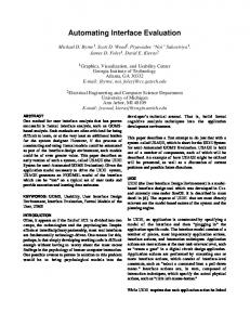
The speedup of the hardware core over the software implementation (Fig. 7) increases with image size. The fully pipelined hardware 1-D FFT can compute an N-length transform every N clock cycles. As the problem size increases linearly, the length of time computing the transform increases linearly for the hardware core and exponentially for the software implementation (some matrices can be more/less efficiently computed due do the cache architecture - as we experienced with a 256 × 256 image). In addition, the effect of the communication latency is lessened for larger images. A speedup of 19 is obtained for the largest tested image size, 512 × 512, and is likely to further increase with larger images, provided sufficient memory resources are available.
12
8 4
Speedup
0
32
64 128 256 S ize of Image (N × N )
512
Fig. 7. Speedup of the SAR algorithm implemented using the USURP framework as compared to GSL.
6
6. FLIGHT ARCHITECTURE
Data Throughput (MB/s)
10
Due to the physical requirements of the flight system, the PCI Mezzanine Card (PMC) RC board used in the prototype system must be replaced with an embedded solution. While this integrated design may add to the total cost of the board, it will remove potential performance bottlenecks. However, the extended design will be functionally compatible with the COTS version because of the USURP framework.
GSL USURP 1
32
64
128
256
512
6.1 Proposed Architecture The main components of the proposed flight system include the CPU, the system controller, SDRAM, dual-port SRAM, and the FPGA. The system controller can provide DMA functionality, which will alleviate the processor’s responsibility during memory transfers. The CPU has access to system SDRAM as well as the dual-port SRAM. The dual-port SRAM will be assigned a small section of the processor’s memory-map. The processor, an IBM PPC750fx, will be separated from the FPGA, a Virtex series, by using several banks of dual-port SRAM. Fig. 10 shows the planned board architecture.
0.1
S ize of Image (N × N )
Fig. 8. Data throughput (higher is better) for the SAR algorithm implemented using the GSL and USURP frameworks.
10000
GSL
Frames / s
1000
USURP
100
10
1
32 0.1
64
128
256
512
S ize of Image (N × N )
Fig. 9. Frames per second (higher is better) for the SAR algorithm implemented using the GSL and USURP frameworks.
Fig. 10. Proposed Flight Board Architecture.
The CPU and the FPGA will be located in separate clock domains, reducing board design constraints. Additionally, separate clock domains will allow the FPGA to run at any necessary speed, instead of forcing a design to run at a specific frequency to match the communication bus clock domain. Communication between the CPU and the FPGA is accomplished by writing and reading to the SRAM. The SRAM has hardware interrupts that can notify the devices when new data is written (eliminating the need for polling). Additionally, the FPGA may have extra SRAM on the backside of the device. This SRAM can be used for temporary data storage and intermediate calculations needed by the FPGA design. Additionally, there is circuitry to support FPGA reconfiguration using either Xilinx’s SelectMAP protocol or JTAG.
The data throughput for GSL and USURP (Fig. 8) have opposite trends. As the image size increases, the software implementation loses 28% of its potential data throughput due to the increasing computational complexity. The hardware throughput increases because larger DMA transfers mask the overhead latency. The experimental results show that DMA transfers above 16 kB (equivalent to a 128 × 128 image) have minimal improvement in data throughput. A 512 × 512 complex matrix (16-bit fixed-point) allows for only 0.45 frames/s to be processed (Fig. 9). As with the software implementation, the hardware algorithm’s frame rate decreases exponentially with the image size due to the increase in throughput requirements.
7
6.2 Dependable FPGA Services
voting logic (Fig. 11). However, due to the power budget of the flight board, this approach may not be practical.
Extra attention must be made to the effects of single-event upsets (SEUs) on the FPGA due to radiation. In addition to normal transient effects that will occur in all non-radiationhardened electronics, SRAM-based FPGA’s can have persistent faults caused by an SEU-modified configuration memory. These types of errors will persist until the FPGA configuration memory is reconfigured. There are several methods that can be used to handle these faults.
6.3 Performance Comparisons In the prototype DM system, the CPU can only communicate with the FPGA by using the PCI bus. The PCI bus limits the theoretical throughput of any FPGA design to 264 MB/s (at 66 MHz). In practice, due to protocol overhead and other issues, the theoretical throughout is not achieved. The peak throughput performance measured on the prototype system is 198.5 MB/s for DMA reads and 95.8 MB/s for DMA writes.
One approach that will be used is known as scrubbing. In this approach, the configuration of the FPGA is reconfigured at a specified rate (much higher than the expected SEU rate). While this approach will correct any configuration memory errors, it does not guarantee that data errors that have already occurred will not propagate further.
The CPU-to-FPGA throughput of the flight system is limited by the memory controller’s nominal DMA transfer rate, the speed of the dual-port SRAM, and the speed of FPGA design. Most FPGA designs are not capable of reaching much higher than 200 MHz and the dual-port SRAM will be capable of 200 MHz operation.
While the previous approach can help to mitigate errors, it does nothing to correct errors that do occur. A second faultmitigation technique is the use of process-level replication. Essentially, every job that is run on the FPGA will be run multiple times. Between runs, the FPGA will be reconfigured in order to avoid the accumulation of errors in the FPGA configuration memory. The results of the runs will be compared to ensure correct results.
The CPU will be able to access SRAM data at a rate of 800 MB/s using 32-bit reads and writes. Using the DMA capabilities of the memory controller, data can be transferred from main memory to the dual-port SRAM with only minimal CPU intervention. As a worst-case scenario, we provide the following flight system predictions (Table 2) based on the same overhead ratios as the PCI bus observed in the testbed. Transferring data to the dual-port SRAM should be more efficient than transferring data to the PCI bus due to less communication overhead; we are in the process of building simulation models to verify the throughput of the flight system.
Another mitigation technique, triple modular redundancy (TMR), can be used internally by the FPGA to ensure that a single SEU will not produce invalid data. A tool to produce TMR code from a pre-existing design is available from Xilinx under the name TMRtool. This approach works well if the FPGA is under utilized. However, if the FPGA is close to capacity, the design will be too large for the FPGA after being triplicated.
Table 2 Predicted Flight System Speedup Operation DMA Write Execution DMA Read Total
Testbed (ms) 5.04 15.92 (66 MHz) 10.44 31.40
Flight (ms) 1.66 8.49 (125 MHz) 3.44 13.60
Speedup 3.03 1.87 3.03 2.31
The FPGA’s execution on the testbed is limited to 66 MHz due to the core sharing the clock domain with the PCI bus. The flight system separates the clock domains and will allow the core to execute at its maximum possible frequency, currently 125 MHz. The flight system can expect at least a 2.31× speedup of the accelerated SAR algorithm, which is a 43× speedup over the GSL software implementation. Additional speedups can come from efficient use of the dual-port SRAM, as part of the communication and execution can be overlapped.
Fig. 11. Example of Chip-level TMR
Another approach to FPGA fault-mitigation is the use of chip-level TMR. Instead of a single FPGA, three FPGAs are used and their outputs are compared using rad-hard
8
7. CONCLUSIONS
[6] K. Compton and S. Hauck, “Reconfigurable Computing: A Survey of Systems and Software,” ACM Computing Surveys, 34(2), Jun 2002, pp. 171-210.
This paper presented an extension to the USURP framework that abstracts hardware resources from the application developer. The Hardware Abstraction API allows earth and space scientists to use accelerated resources without needing to understand FPGA development. The API is based around a familiar framework (GSL) and allows application developers to seamlessly transition between terrestrial system and the spacecraft’s embedded system.
[7] J. Greco, B. Holland, I. Troxel, G. Barfield, V. Aggarwal, and A. George, “USURP: A Standard for Design Portability in Reconfigurable Computing,” submitted to IEEE Symp. on Field-programmable Custom Computing Machines (FCCM), Napa Valley, CA, Apr 24-26, 2006. [8] M. Galassi, J. Davies, J. Theiler, B. Gough, G. Jungman, M. Booth, and F. Rossi, GNU Scientific Library Reference Manual - Revised Second Edition, United Kingdom: Network Theory Limited, 2005.
A Synthetic Aperture Radar hardware-accelerated core was developed as a case study. The core is interfaced through the FPGA Software Interface API to the RCGSL framework. Using the FPGA as a SAR coprocessor, we can achieve a speedup of 19 when compared to a software implementation developed with GSL on the testbed.
[9] A. Hein, Processing of SAR data: fundamentals, signal processing, interferometry, Berlin: Springer-Verlag, 2004
The speedup trend is expected to rise in the final flight system. The DM spacecraft will remove the PCI bottleneck to allow for a greater data throughput; a worst-case speedup of 43 over the GSL implementation is estimated. A greater amount of FPGA-accessible SRAM will allow us to process larger image sizes.
[10] R. Raney, H. Runge, R. Balmer, I. Cumming, and F. Wong, “Precision SAR Processing Using Chirp Scaling,” IEEE Trans. on GeoScience and Remote Sensing, 32(4), Jul 1994, pp. 786-799. [11] P. G. Meisl, M. R. Ito, I. G. Cumming, “Parallel Synthetic Aperture Radar Processing on Workstation Networks,” Proc. of 10th International Parallel Processing Symp. (IPPS), Washington, DC, Apr 15-19, 1996.
ACKNOWLEDGEMENTS This work was supported in part by the NMP Program at NASA, our Dependable Multiprocessor project partners at Honeywell Inc., and the Florida High-Technology Corridor Council.
[12] J. Samson, J. Ramos, I. Troxel, R. Subramaniyan, A. Jacobs, J. Greco, G. Cieslewski, J. Curreri, M. Fischer, A. George, V. Aggarwal, M. Patel, and R. Some, “HighPerformance, Dependable Multiprocessor,” Proc. of IEEE/AIAA Aerospace, Big Sky, MT, Mar 4-11, 2006 (to appear).
REFERENCES [1] Home page of NASA’s New Millennium Program, nmp.jpl.nasa.gov.
[13] F. E. Ortiz, J. P. Durbano, J. R. Humphrey, P. F. Curt, and D. W. Prather, “A FPGA-Based Architecture for InFlight SAR Motion Compensation in UAVs,” in Proc. of International Conference on Military and Aerospace Programmable Logic Devices (MAPLD), Washington, DC, Sep 7-9, 2005.
[2] J. Ramos, R. Sowada, and D. Lupia, “Scientific Computing in Space Using COTS Processors,” Proc. of International Conference on Military and Aerospace Programmable Logic Devices (MAPLD), Washington, DC, Sep 7-9, 2005.
BIOGRAPHIES
[3] N. Bergmann, and P. Sutton, “A High-Performance Computing Module for a Low Earth Orbit Satellite Using Reconfigurable Logic,” Proc. of International Conference on Military and Aerospace Applications of Programmable Logic Devices (MAPLD), Greenbelt, MD, Sep 15-16, 1998.
James Greco is a Ph.D. student in the Electrical & Computer Engineering Department at the University of Florida. He is a research assistant and member of the Advanced Space Computing and Reconfigurable Computing groups at the High-performance Computing & Simulation Research Laboratory. His research interests include reconfigurable computing in HPC and the acceleration of signal processing applications. He is a student member of IEEE.
[4] E. Wells and S. Loo, “On the Use of Distributed Reconfigurable Hardware in Launch Control Avionics,” Proc. of Digital Avionics Systems Conference, Daytona Beach, FL, Oct 14-18, 2001. [5] A. Dawood, S. Visser, and J. Williams, “Reconfigurable FPGAs for Real Time Image Processing in Space, ” in Proc. of International Conference on Digital Signal Processing, Santorini, Greece, Jul 1-3, 2002. 9
Grzegorz Cieslewski is a graduate student at the University of Florida where he is currently pursuing a Ph.D. degree in Electrical and Computer Engineering. As a research assistant he is a member of Advanced Space Computing and Reconfigurable Computing groups at High-performance Computing & Simulation Research Laboratory. His research interests include computer architecture, reconfigurable, fault-tolerant and distributed computing as applied to linear algebra problems and signal processing. He is a student member of IEEE. Adam Jacobs is a Ph.D. student in Electrical and Computer Engineering at the University of Florida. He is a research assistant in the Advanced Space Computing and Reconfigurable Computing groups at the High-Performance Computing and Simulation Research Laboratory. His research interests include fault-tolerant FPGA architectures and high-performance computing. He is a student member of the IEEE. Ian Troxel is a Ph.D. candidate in Electrical and Computer Engineering at the University Florida. He is a research assistant who co-leads the advanced space computing and the reconfigurable computing research groups at the High-performance Computing and Simulation Research Laboratory. His research interests include reconfigurable and embedded computing and he is a student member of the IEEE. Alan D. George is Professor of Electrical and Computer Engineering at the University of Florida, where he serves as Director and Founder of the HCS Research Laboratory. He received the B.S. degree in Computer Science and the M.S. in Electrical and Computer Engineering from the University of Central Florida, and the Ph.D. in Computer Science from the Florida State University. Dr. George's research interests focus on highperformance architectures, networks, services, and systems for parallel, reconfigurable, distributed, and fault-tolerant computing. He is a senior member of IEEE and SCS, and can be reached by e-mail at
[email protected].
10